
Related Manuals for HYDAC International FCU8111/-Aviation


Summary of Contents for HYDAC International FCU8111/-Aviation
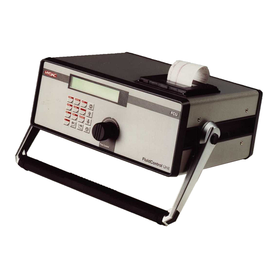
- Page 1 FluidControl Unit FCU8111 /-Aviation Valid until series no. 0002S00790K0009999 Valid from Hardware index up Valid for firmware versions > 3.32 <Platzhalter> Titelbild Operating instructions 3690427b / 2023-10...
- Page 2 Translation / original language: English © 2023 HYDAC Filter Systems GmbH. All rights reserved. ® All product names used may be trademarks or registered trademarks of HYDAC or the particular owner. This manual was prepared to the best of our knowledge. Nevertheless and despite the greatest care, it is possible that it may contain errors.
-
Page 3: Table Of Contents
TABLE OF CONTENTS Table of Contents General ........................... Target group of the manual ................Illustrations in the manual................... 1.2.1 Show warning signs................1.2.2 Representation of requirements ............1.2.3 Representation of procedural instructions ..........1.2.4 Representation of intermediate results/results ........1.2.5 Supplementary symbols ............... -
Page 4: Fig. 22 Memory Menu
TABLE OF CONTENTS Commissioning ....................Default settings and limit values..................Operation ........................Display........................ Operating the FCU ..................... Overview menu....................7.3.1 Menu – MODE, selecting the operating mode........7.3.2 MEMORY menu ................... 7.3.3 PRINT menu..................7.3.4 LIMITS – menu ..................7.3.5 SETUP menu.................. -
Page 5: General
1. GENERAL General 45035996988833419 Before you use this product for the first time, read this manual at least up to the chapter "Operation". If you would like to carry out maintenance or troubleshooting, you can find the procedure in the respective chapters. The use and the handling of the product as well as its use are not self-explanatory and are described in detail in this manual. - Page 6 1. GENERAL Read and observe the warnings carefully and follow the steps provided precisely. Warnings visually highlighted in boxes Warnings visually highlighted in boxes provide the following information in relation to a danger: DANGER High electrical voltages Life-threatening injuries or death! Disconnect system from power supply and secure it against being started up again.
-
Page 7: Representation Of Requirements
1. GENERAL Warning level What this means for you Warns of dangers for persons with high risk potential. DANGER Failure to observe this warning will most likely result in serious injury or even death. Warns of dangers for people with medium risk potential. WARNING Failure to observe this warning may result in serious injury or even death. -
Page 8: Representation Of Intermediate Results/Results
1. GENERAL 1.2.4 Representation of intermediate results/results 9007199396760075 In the case of some activities, it is necessary to carry out work steps with intermediate results and end results. Intermediate results are the consequence of activities; they are marked with an indented arrow. -
Page 9: Safety
2. SAFETY Safety 9007201546450571 The product is designed as safe. In spite of that, there is danger in some actions that can only be avoided by using the right procedures. These correct procedures and points, which must be followed, are described in this manual. - Page 10 2. SAFETY Activity Personnel Knowledge Commissioning Specialist Safe handling/use of tools. personnel - Product-specific knowledge is required. Mechanical Specialist personnel - Electrical Handling, Operating Product-specific knowledge is required. operation, personnel - Knowledge about handling the operating operation monitoring General fluid/operating medium is required Troubleshooting Mainte- Specialist Safe handling/use of tools.
-
Page 11: Hazard Symbols / Pictograms
2. SAFETY Hazard symbols / pictograms 9007201546460171 The following are the safety symbols / pictograms in this manual. They indicate specific dangers to persons, property or to the surroundings. Observe these safety symbols / pictograms and act with particular caution in such cases. Always keep all symbols / pictograms complete and legible. - Page 12 2. SAFETY Hazardous to the environment Others symbols used These marks can be found for all safety and warning instructions in this manual which indicate a particular danger to persons, property or the environment. Exposed electrical components Danger due to operating pressure 12 / 84 3690427b / 2023-10...
- Page 13 2. SAFETY Signs used for the required specialist personnel These symbols show the required training/knowledge for installation work and/or main- tenance work. Specialist personnel – General / Operating personnel These persons have a specialist training and several years of work expe- rience.
-
Page 14: Danger Notifications
2. SAFETY Danger notifications 2291762059 The following residual risks can occur in the various life phases of the product: Life phase - Commissioning / Operation The following risks could arise during the commissioning / operation life phase: WARNING Hydraulic system is under pressure Danger of bodily injury The hydraulic system must be depressurized before performing any work on it. -
Page 15: Stoppage In An Emergency (Emergency Stop)
2. SAFETY Stoppage in an emergency (EMERGENCY STOP) 27021597827479947 Disconnect the product from all sources of energy in an emergency. Switch off the product at the main switch. Fire-fighting / Extinguishing a fire 63050394846859019 Use a powder extinguisher that corresponds to the fire class B EN 2 to extinguish any fires / to fight fires. -
Page 16: Product And Technical Specifications
3. PRODUCT AND TECHNICAL SPECIFICATIONS Product and technical specifications 9007201434997771 The FluidControl Unit FCU can determine the solid particle contamination of mineral oils on a continuous basis. With the FCU, it is possible to record, save and display the particle counts for 6 particle sizes and the cleanliness class completely automatically during continuous operation in accordance with NAS 1638 or ISO 4406. -
Page 17: Checking The Scope Of Delivery
3. PRODUCT AND TECHNICAL SPECIFICATIONS Checking the scope of delivery 2182018315 Here you will find the scope of delivery for the product. ● Check the packaging and the product for damage. Report any damage in transit to the forwarding agent or the HYDAC department in charge. -
Page 18: Intended Use
3. PRODUCT AND TECHNICAL SPECIFICATIONS Intended Use 9007201438029707 Use the FluidControl Unit only for the application described in the following. The FluidControl Unit FCU is used for temporary or continuous monitoring of solid particle contamination in hydraulic systems. Proper/designated use of the product extends to the following: ●... -
Page 19: Technical Data
3. PRODUCT AND TECHNICAL SPECIFICATIONS Technical data 9007201436360715 If you are aware of the technical data of the product, you will be able to use it optimally. This chapter provides the technical data of the product: Measured value display Continuous view in LCD display Self diagnostics Continuous self-monitoring with error indi- cation in LCD display... -
Page 20: Tab. 6 Storage Conditions
3. PRODUCT AND TECHNICAL SPECIFICATIONS Protection class III (safety extra-low voltage) Protection class IP40 Weight when empty ≈ 14 kg Tab. 5: Technical Data Permitted storage temperature range -20 … 80°C / -4 … 185°F Relative humidity ≤ 90%, non condensing Clean, salt-free air, not near oxidizing substances (rust film). Storage duration After draining and flushing fully, unlimited. -
Page 21: Decoding The Name Plate
3. PRODUCT AND TECHNICAL SPECIFICATIONS Decoding the name plate 2183393803 Details for identifying the product are found on the name plates on the product as well as their components. Always mention the part no. and the serial no. when contacting HYDAC. -
Page 22: Operating Elements And Dimensions
3. PRODUCT AND TECHNICAL SPECIFICATIONS Operating elements and dimensions 2183072523 The operating elements and dimensions of the FCU are as follows: Fig. 4: Operating elements and dimensions A High-pressure port INLET B Return port connection OUTLET C Switch - On/Off D Electrical connection 24 V DC E Serial interface F Control port G Sealing cover... -
Page 23: Hydraulic Diagram
3. PRODUCT AND TECHNICAL SPECIFICATIONS Hydraulic diagram 2182330251 The hydraulic diagram of the FCU is as follows: Fig. 5: Hydraulic diagram Optical sensor 5 Flow transmitter Flow regulator (adjustable) 8 Filter Flow control valve 23 / 84 3690427b / 2023-10... -
Page 24: Function Description
3. PRODUCT AND TECHNICAL SPECIFICATIONS Function description 2182326411 The functional description is as follows: Fig. 6: Function diagram Optical sensor Laser light source Photodetector Evaluation electronics Flow transmitter Display Flow regulator (adjustable) Filter Flow control valve 12 Keyboard Serial interface 14 Printer Relay A continuous oil flow runs through a visual sensor (1) comprised of a laser light source (2) and a photo receiver (3). - Page 25 3. PRODUCT AND TECHNICAL SPECIFICATIONS Unless set otherwise, the following information is displayed continuously during the measurement: ● selected measurement mode ● Progress of the ongoing measurement ● Current value of the measurement results for 2 of the 4 particle size channels ●...
-
Page 26: Transportation / Storage
4. TRANSPORTATION / STORAGE Transportation / Storage 2194570251 You will find the respective notice on the prevention of damage to the product during transport or storage in this chapter. Adjusting the carry and support handle The FCU has a carry and support handle to make the transportation and work easier. To set the desired carrying or supporting position, proceed as follows: Hold down both release buttons (a) at the same time and select the desired position of the carry and support handle (b). -
Page 27: Fig. 8 Transporting In A Horizontal Or Vertical Position
4. TRANSPORTATION / STORAGE Fig. 8: Transporting in a horizontal or vertical position Always carry the FCU by the carry and support handle or transport the FCU in the appropriate accessory case (see Accessories). Fig. 9: Transporting by hand or in a transport case Storing the FCU Note the permitted ambient conditions for storage, see ▶Sec. 3.4 "Technical data". -
Page 28: Fig. 10 Storing The Fcu
4. TRANSPORTATION / STORAGE Fig. 10: Storing the FCU 28 / 84 3690427b / 2023-10... -
Page 29: Assembly, Installation And Commissioning
5. ASSEMBLY, INSTALLATION AND COMMISSIONING Assembly, installation and commissioning 9007201450732043 An optimally assembled and installed product ensures a safe and continuous operation. Installing the FCU 9007201451368587 Use the carry and support handle to position the FCU ergonomically in the working area. -
Page 30: Electrical Connection
5. ASSEMBLY, INSTALLATION AND COMMISSIONING Electrical connection 2196634635 The FCU is equipped with a battery. It allows you to measure independently of the power supply and to print out the measurement results for ≈ 5 hours. The battery is charged automatically when the power supply unit is plugged in even if the FCU is switched off at the switch. -
Page 31: 5.2.2.1 Serial Interface - Pin Assignment
5. ASSEMBLY, INSTALLATION AND COMMISSIONING 5.2.2.1 Serial interface - Pin assignment 2197701643 The serial interfaces have the following pin assignment. RS232 An appropriate cable for connecting to a PC is included in the scope of delivery. Description Shield Transmission line Receiving line Ground Fig. 15: RS232... -
Page 32: 5.2.2.2 Control Interface - Pin Assignment
5. ASSEMBLY, INSTALLATION AND COMMISSIONING 5.2.2.2 Control interface - Pin assignment 2196697739 2 A is the maximum load for the relay contacts. The maximum switching voltage is: 24 V DC / 50 V AC, the maximum switching capacity: 30 W / 50 VA. Description 24 V DC Operating voltage (12 V in battery oper- ation), maximum load capacity 200 mA Ground Battery switch-off... -
Page 33: Tab. 7 Relay 1 / Relay 2 - Mode 1 M1
5. ASSEMBLY, INSTALLATION AND COMMISSIONING Relay functions of relay 1 / relay 2 / relay 3 The following tables show the switched position of the relays in the various operating modes in keeping with the operating condition or measurement result. Mode 1 Relay 1 Relay 2 Measurement Measurement After the first... -
Page 34: Tab. 8 Relay 1 / Relay 2 - Mode 2 M2
5. ASSEMBLY, INSTALLATION AND COMMISSIONING Mode 2 Relay 1 Relay 2 Outside range Measured After switching Measured After switching on value ≤ lower on or starting a value ≤ lower or starting a limit or measurement limit or measurement or Measured Measured lower limit < value ≥... -
Page 35: Tab. 11 Relay 1 / Relay 2 - Mode 5 M5
5. ASSEMBLY, INSTALLATION AND COMMISSIONING Mode 5 Relay 1 Relay 2 Measurement Measurement After the first Flow rate within currently in stopped measured the target range progress value is available: Flow error Tab. 11: Relay 1 / Relay 2 – Mode 5 M5 Mode Relay 3 All operating modes ready for operation Not ready for operation Tab. 12: Relay 3... -
Page 36: Connecting The Hydraulics
5. ASSEMBLY, INSTALLATION AND COMMISSIONING Connecting the hydraulics 2196636555 The subsequent chapters provide details on connecting the FCU. WARNING Hydraulic system is under pressure Danger of bodily injury The hydraulic system must be depressurized before performing any work on it. 5.3.1 Connection for measurement using the high pressure inlet 2198155787... -
Page 37: Commissioning
5. ASSEMBLY, INSTALLATION AND COMMISSIONING Commissioning 9007201452865419 Proceed as follows for commissioning: Conducting Measurements via the High-Pressure Port INLET ü The FCU is connected electrically, see ▶Sec. 5.2.1 "Connecting the power supply" for details. ü The FCU is connected hydraulically, see ▶Sec. 5.3.1 "Connection for measurement using the high pressure inlet"... -
Page 38: Default Settings And Limit Values
6. DEFAULT SETTINGS AND LIMIT VALUES Default settings and limit values 2252650123 The following default settings are defined and the limit values are possible: Menu POWERUP Language English Test volume 100 ml Menu MEMORY Measuring point HYDAC FCU 8110 Averaging interval 0 min Memory mode overwrite... -
Page 39: Tab. 13 Default Settings
6. DEFAULT SETTINGS AND LIMIT VALUES Lower M4:limit values 5/5/5 NAS Upper M4:limit values 10/10/10 NAS M4:Test cycle time 120 min M5:Start delay 10 s Number of M5:measurements Tab. 13: Default settings 39 / 84 3690427b / 2023-10... -
Page 40: Operation
7. OPERATION Operation 9007201450726667 Procedures, notes and tips for optimum, fault-free operation can be found in this chapter. Switch the FCU on or off at the main switch on the rear side. When the FCU is switched on, information about the device type such as the firmware version, memory allocation, bus address, battery charge status, set viscosity range, error messages, etc. - Page 41 7. OPERATION (MODE M1, M2, M4) or the target cleanliness ((MODE M3) is achieved. This sequence of single measurements is simply referred to as a measurement. Protocol: A measurement is described by a protocol. It is comprised of the log header and the log lines.
-
Page 42: Display
7. OPERATION Display 9007201500981131 You will see the following information on the display: Fig. 20: Display in the example of an FCU2xxx-x 1 Current operating mode MODE M1 (measuring the cleanliness class). 2 Display of the measured flow rate (≈ 50 ml/min recommended). 3 Indicates the elapsed measuring time in %. Begins at 0%; the cleanliness class is displayed again at 100%. -
Page 43: Operating The Fcu
7. OPERATION 4 Display of the currently derived fluid cleanliness. Use the ISO, SAE/NAS and particles keys to switch between the view in the ISO or NAS (FCU811x) or SAE (FCU821x) classes and the display of the particle counts. In the view of the cleanliness class in the NAS or SAE class, the numbers / letters in brackets indicate the selected particle size ranges: ●... -
Page 44: Overview Menu
7. OPERATION Scrolling in the menus (when the menu sign is displayed) Scroll through Selection. Increasing / decreasing the numbers and letters (in input mode) Select measurement operation Basic settings (with/without relay actuation) (Autostart, date, time, etc.) Editing measured value memory Displaying the ISO-Code (Name of the measuring point, (This key responds only when a... -
Page 45: Menu - Mode, Selecting The Operating Mode
7. OPERATION 7.3.1 Menu – MODE, selecting the operating mode 2207364491 In the MODE menu, select the operating mode in which the measurement is carried out. After switching on, the last used operating mode is set. M1: Measure M2: Measure + Switch M3: Filter until M4: Filter from to M5: Measure + Autostop... - Page 46 7. OPERATION If the lower limit value is reached or if it is undershot, then the FCU switches off the unit to be controlled and the test cycle time begins. After the test cycle time has elapsed, the FCU carries out a check measurement (100 ml) and checks whether the measured values lie within the limit values.
-
Page 47: Memory Menu
7. OPERATION 7.3.2 MEMORY menu 2207809419 In the MEMORY menu, you can set the storage of protocols. The percentage in the display indicates the memory usage. In other words, at 0.0% = Memory empty <-> 100% = Memory full. Measuring point Measuring point xx Averaging interval Designation xx x min. -
Page 48: Tab. 16 Available Character Set
7. OPERATION Available character set: " & ‘ ä é è ê ö ü ß Tab. 16: Available character set To insert a space or to correct the last character, use the following key combination: Insert a space Delete character Function of the Keys Confirm inputs Cancel entry Scroll through Selection. -
Page 49: Delete All
7. OPERATION ● Date ● Date + Measuring point Delete all This menu item enables the entire log memory to be deleted Change measuring point This menu item enables the designation of a measuring point to be changed. Set memory mode Here, select how the protocol memory behaves if it is fully occupied. -
Page 50: Print Menu
7. OPERATION 7.3.3 PRINT menu 2251681035 The PRINT menu enables the printing of stored protocols, ongoing measurements, table of contents, and parameter list to be started. Logs Number List Graph Date List Graph Measuring point List Graph Date + Measuring point List BS-Logs Graph... - Page 51 7. OPERATION ● Number ● Date ● Measuring point ● Date ● Date + Measuring point BS reports The saved reports from the Bottle Sampling operation can be output via the built-in printer. Summary A summary of the logs stored in memory is printed out. For every protocol stored, the protocol number, the designation of the measuring point, the start and stop time, and the number of protocol lines are output.
-
Page 52: Limits - Menu
7. OPERATION 7.3.4 LIMITS – menu 2252274315 In the LIMITS menu, the required settings (switching value) can be configured for the different operating modes.. M2: Relay 1 M2: R1 Measurement channel Switching value M2: R1 Switch func No function Within range Outside range Exceed M2: Relay 2... -
Page 53: Tab. 17 Switching Value
7. OPERATION FCU 81xx FCU 82xx 2 µm NAS A - 4 µm SAE 5 µm NAS B - 6 µm SAE 15 µm NAS C - 14 µm SAE 25 µm NAS D - 21 µm SAE 50 µm NAS E - 38 µm SAE 100 µm NAS F - 70 µm SAE 2 µm ISO 4 µm ISO 5 µm ISO... -
Page 54: Setup Menu
7. OPERATION 7.3.5 SETUP menu 9007201507093643 The SETUP menu enables the configuration of settings which apply to several or all the operating modes. Autostart M1: Measure M2: Measure + Switch M3: Filter until M4: Filter from to Cancellation at Q=0 Pump start delay x [s] Date / Time... -
Page 55: Checking The Battery Voltage
7. OPERATION Setting the pump lead time In case of measurements which are performed with the aid of an external pump or an external filter unit (e.g. OF5C), this function enables the user to operate the pump for a limited period of time within which a flow rate must be set on the FCU. If the FCU does not determine any flow after the set lead time of the pump has elapsed, the measurement is stopped and the unit actuated by means of a relay is switched off to prevent any damage caused by the dry running of the pump. -
Page 56: Menu - Powerup
7. OPERATION 7.3.6 Menu – POWERUP 2252417803 The POWERUP menu is available only after switching on, when a measurement has not yet started. Here, settings which are normally only seldom changed are configured. You can go to the POWERUP menu by pressing the two keys at the same time. POWERUP Language English... -
Page 57: Rectifying Malfunctions
8. RECTIFYING MALFUNCTIONS Rectifying malfunctions 9007201273636875 In order to get quick and immediate assistance in the case of errors, you will find the most often occurring errors with their cause and remedy with suitable specialist personnel in this chapter. Error message Cause(s) Remedy Invalid parameter... - Page 58 8. RECTIFYING MALFUNCTIONS Error message Cause(s) Remedy Number of defective The self-monitoring function of The defective protocols are logs: the FCU has detected a deleted automatically. After checksum error in one or switching on the next time, more stored protocols. this message does not appear Possible causes: again if it was short-term error.
- Page 59 8. RECTIFYING MALFUNCTIONS Error message Cause(s) Remedy Flow error! Oil does not flow through the Turn the flow regulator particle sensor (possibly only clockwise. Correct: 0 ml air). Check the position of the The flow transmitter is faulty. change-over valve. The measurement volume is Check the hydraulic connec- at 0 in the PowerUp menu.
-
Page 60: Tab. 18 Error/Cause/Rectification
8. RECTIFYING MALFUNCTIONS Error message Cause(s) Remedy Reload languages The internal memory for Transfer the FCU languages languages has been partially to the FCU using the PC changed due to an internal software FluMoS. fault. If the error recurs, send the The internal back-up battery is FCU to HYDAC for repair. -
Page 61: Carrying Out The Maintenance
9. CARRYING OUT THE MAINTENANCE Carrying out the maintenance 9007201273850891 For a long, trouble-free service life of the product, regular maintenance activities are required. Carry out the specified adjustment, maintenance and inspection work every six months or, at the latest, when an error message / malfunction makes it necessary. Cleaning the FCU 2091930507 Clean the control panel with a clean, moist cloth. - Page 62 9. CARRYING OUT THE MAINTENANCE 3. Unscrew the screw plug with an Allen wrench = 6 mm in counterclockwise direction. 4. Pull the filter element out upwards with needle-nose pliers and dispose of the old filter element properly in an environ- mentally correct manner. 5.
-
Page 63: Inserting The Printer Paper
9. CARRYING OUT THE MAINTENANCE 10. Insert the screw plug and turn it clockwise by hand. Tighten the screw plug with a wrench = 19 mm. O The replacement of the filter element is now complete. Inserting the printer paper 9007201483587595 You can find a suitable paper roll for the printer here ▶Sec. 11.2 "Finding spare parts and accessories". - Page 64 9. CARRYING OUT THE MAINTENANCE 6. Remove the axis from the used paper roll and place it in the new paper roll. 7. Feed the start of the new paper roll into the slot. 8. Turn the transport roller with your finger to feed the paper through.
- Page 65 9. CARRYING OUT THE MAINTENANCE 13. Close the cover of the dot-matrix printer. 14. Switch on the FCU at the switch. O Changing the paper roll / ribbon is complete. 65 / 84 3690427b / 2023-10...
-
Page 66: Decommissioning / Disposal
10. DECOMMISSIONING / DISPOSAL Decommissioning / Disposal 99079191859273099 In the following chapters, you will be provided with information regarding temporary shutdown/final decommissioning and disposal of the product. 10.1 Temporary shutdown 253902219 If the product is being temporarily shut down, the following measures are adequate: 1. -
Page 67: Appendix
11. APPENDIX Appendix 9007201274761739 This Appendix contains additional information on the product. 11.1 Contacting Customer Service 63050394840444939 Contact data such as the telephone numbers, e-mail and mailing addresses for the Hotline, product support, Customer Service, Branches, service partners for mainte- nance, repair and spare parts can be found, always updated, on our homepage www.hydac.com. -
Page 68: 11.2.1 Finding Accessories
11. APPENDIX Qty Description Auxiliary Part no. Single-ended cordset for the power supply unit Euro plug, L= 2 m Single-ended cordset for the power supply unit Plug for UK, L= 2 m Single-ended cordset for the power supply unit Plug for USA, L= 2 m Single-ended cordset for the power supply unit Plug for AUS, L= 2 m Set of paper rolls, dot-matrix printer... -
Page 69: 11.3 Declaration Of Conformity
Mathias Dieter Dipl.Kfm. Wolfgang Haering Günter Harge Registered seat of company: 66280 Sulzbach / Saar - Germany c/o HYDAC International GmbH, Industriegebiet, 66280 Sulzbach / Saar Registry Court: Saarbrücken, HRB 17216 Telephone: +49 6897 509 1511 Value added tax identification number : DE 815001609... - Page 70 11. APPENDIX HYDAC FILTER SYSTEMS GMBH Industriegebiet 66280 Sulzbach / Saar Germany Internet: www.hydac.com UK Declaration of conformity This declaration of conformity is issued under the sole responsibility of the manufacturer. We hereby declare under sole responsibility that the following designated product, on the basis of its design and construction and in the version which we have brought to market complies with the fundamental safety and health requirements contained in the directives and standards listed below.
-
Page 71: 11.4 Overview And Definition Of The Cleanliness Classes
11. APPENDIX 11.4 Overview and definition of the cleanliness classes 9007199312030859 The subsequent chapters provide the definition of the cleanliness classes ISO 4406, SAE AS 4059 and NAS 1638. 11.4.1 Cleanliness classes according to ISO 4406 18014398566775947 With the cleanliness classes according to ISO4406, the particle counts are determined cumulatively, i.e. -
Page 72: Tab. 22 Cleanliness Class Iso 4406 Overview - Cleanliness Classes <-> Particle Counts
11. APPENDIX ISO code Number of particles per 100 ml More than Up to (and including) 500000 1000000 1000000 2000000 2000000 4000000 4000000 8000000 8000000 16000000 16000000 32000000 32000000 64000000 64000000 130000000 130000000 250000000 Tab. 22: Cleanliness class ISO 4406 Overview – Cleanliness classes <-> Particle counts Increasing the ISO code by 1 doubles the particle count per 100 ml. -
Page 73: Tab. 24 Iso4406:1987 To Iso4406:1999
11. APPENDIX Overview of modifications - ISO4406:1987 to ISO4406:1999 "old" ISO 4406:1987 "new" ISO 4406:1999 Size ranges > 5 µm > 4 µm > 15 µm > 6 µm > 14 µm Dimension deter- Longest dimension Diameter of the mined of a particle circle of equal area of the particle projection ISO 11171:1999 Test dust ACFTD - dust 1-10 µm... -
Page 74: 11.4.2 Cleanliness Classes According To Sae As4059
11. APPENDIX 11.4.2 Cleanliness classes according to SAE AS4059 18014398566780171 Like the cleanliness class according to ISO 4406, the SAE AS4059 describes the particle concentration in fluids. The analysis procedures can be used in line with ISO 4406. Further compliance with the ISO 4406:1999 is the classification into cleanliness classes on the basis of cumulative particle counts (i.e. -
Page 75: Tab. 25 Overview Of Cleanliness Class Sae As 4059
11. APPENDIX Maximum number of particles per 100 ml Sizes 4402 >1 µm >5 µm >15 µm >25 µm >50 µm >100 µm Sizes >4 µm >6 µm >14 µm >21 µm >38 µm >70 µm ISO11171 Size coding (classes) 1600000 623000 111000 19600 3390 3200000 1250000 222000 39200 6780 1020 Tab. 25: Overview of cleanliness class SAE AS 4059 Definition according to SAE Cleanliness classes according to SAE represent absolute particle counts larger than a defined particle size. -
Page 76: 11.4.3 Cleanliness Classes According To Nas 1638
11. APPENDIX 11.4.3 Cleanliness classes according to NAS 1638 18014398566783883 Like cleanliness class ISO 4406, the NAS1638 describes the particle concentrations in fluids. The analysis methods can be used in the same manner as ISO 4406. In case of NAS 1638, in contrast to ISO 4406, certain particle size ranges are counted and are then attributed key figures. - Page 77 TABLE OF ILLUSTRATIONS Table of Illustrations Fig. 1 Fire protection classification B / Minimum distance for fire fighting ......Fig. 2 Decoding the name plate..................Fig. 3 Model Code ......................Fig. 4 Operating elements and dimensions ................ Fig. 5 Hydraulic diagram..................... Fig.
-
Page 78: List Of Tables
LIST OF TABLES List of Tables Tab. 1 Target groups ......................Tab. 2 Depiction of the warning levels................. Tab. 3 Target group / Required personnel qualification............Tab. 4 Checking the scope of delivery................. Tab. 5 Technical Data......................Tab. 6 Storage conditions....................Tab. -
Page 79: Glossary
GLOSSARY Glossary ISO 4406 ISO4406 is an international standard (norm) on the subject of Fluid technology – Hydraulic pressure fluids. It describes a numerical key for the degree of fluid contamination through solid particles. NAS1638 NAS1638 is an out-of-date National Aero- space Standard regarding hydraulic fluids and contamination of aircraft compo- nents. -
Page 80: Index
INDEX Index Accessories 68 Averaging interval Calibration 61 Setting 48 Changing the filter element 61 Cleaning the 61 Operating 43 Switching on / switching off the 40 Battery status Filter element checking 55 Changing the 61 Function of the Keys 43, 48 Battery switch-off 32... -
Page 81: Tab. 20 Spare Parts
INDEX Measuring point 40 Mode 4 34 Change 49 Mode 5 35 Designating a 47 Relay 3 MEMORY 47 MODE 35 Memory mode Relay functions Overwrite 49 Relay 1 / 2 / 3 33 Setting 49 Stop when full 49 Menu LIMITS 52 SAE AS4059 74... - Page 82 82 / 84 3690427b / 2023-10...
- Page 83 83 / 84 3690427b / 2023-10...
- Page 84 HYDAC Filter Systems GmbH Industriegebiet 66280 Sulzbach/Saar Germany Tel. +49 6897 509-01 filtersystems@hydac.com www.hydac.com Further addresses: www.hydac.com/en/contacts...
Need help?
Do you have a question about the FCU8111/-Aviation and is the answer not in the manual?
Questions and answers