Table of Contents
Advertisement
Quick Links
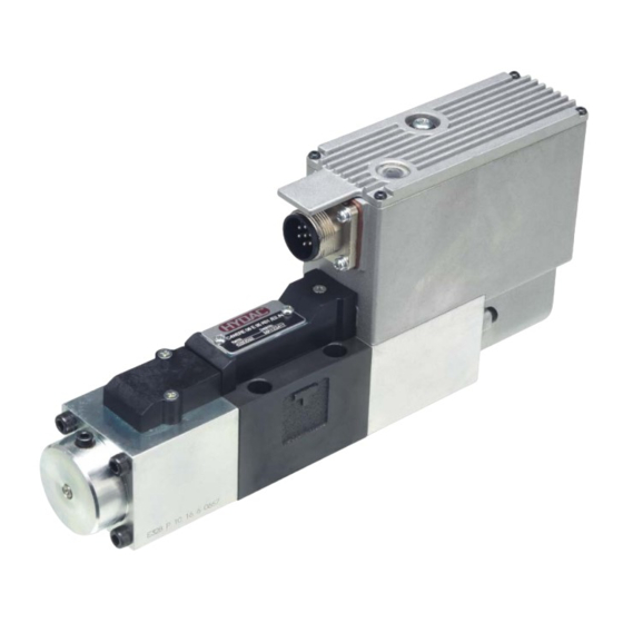
DESCRIPTION
HYDAC 4/3 control valves from the series
C4WERE 6 are direct acting,
electrically operated spool valves.
The valve operates by an oil-immersed
control solenoid.
During this process, the solenoid quickly
and precisely pushes the valve's control
spool into the respective position to obtain
the desired flow path.
The piston position is proportional to the
input signal and is controlled by integrated
electronics and direction control (LVDT).
Instruction manual C4WERE 6
4/3 proportional spool valve
Control valve with on-board electronics and
positional transducer
solenoid-operated, direct-acting
FEATURES
• Application for position, pressure and speed control
• Resistant to contamination thanks to powerful solenoids
• Easy to use thanks to plug-and-play design
• Highly dynamic and very good response
• Interface according to ISO 4401-03; DIN 24340 Form A6
Manufacturer: HYDAC Fluidtechnik GmbH
Justus-von-Liebig-Str.
66280 Sulzbach/Saar
Germany
Phone:
+49 (0)6897 - 509-01
Fax:
+49 (0)6897 - 509-598
E-mail:
valves@hydac.com
Nominal size 6
up to 100 l/min
up to 350 bar
1
Advertisement
Table of Contents

Subscribe to Our Youtube Channel
Related Manuals for HYDAC International C4WERE 6


Summary of Contents for HYDAC International C4WERE 6
- Page 1 FEATURES HYDAC 4/3 control valves from the series • Application for position, pressure and speed control C4WERE 6 are direct acting, • Resistant to contamination thanks to powerful solenoids electrically operated spool valves. • Easy to use thanks to plug-and-play design •...
-
Page 2: Table Of Contents
CONTENTS Introduction............................4 Qualifications for initial start-up of the valve .................. 4 Safety information ........................4 Intended use ..........................4 Improper use ..........................4 Description of function ........................5 Fields of application ........................5 Scope of delivery .......................... 6 1.7.1 Checklist for visual inspection of the valve ... - Page 3 INHALTSVERZEICHNIS Operating the valve ........................... 19 Maintenance and repair ........................19 Dismantling............................20 10 Storage .............................. 20 11 Disposal ............................21 12 Customer service..........................21 13 Intended use / foreseeable misuse ....................21 14 Exclusion of liability for manual ......................21...
-
Page 4: Introduction
INTRODUCTION QUALIFICATIONS FOR INITIAL START-UP OF THE VALVE The valve must only be put into operation by trained specialist personnel with knowledge of hydraulics and electrical systems, or under the supervision of such qualified personnel. Specialist personnel refers to any person who has acquired knowledge through their specialist training regarding the provisions for carrying out the initial start-up work. -
Page 5: Description Of Function
DESCRIPTION OF FUNCTION The solenoid-operated proportional directional spool valves of type C4WERE 6 are used to control a flow precisely and dynamically. The valve comprises a valve housing (1) with corresponding valve piston (2). It has two return springs (3) and is fitted with two powerful regulating solenoids (4), a positional transducer (5) and on-board electronics (6). -
Page 6: Scope Of Delivery
SCOPE OF DELIVERY The parts included in the scope of delivery are listed in the following table. Parts Quantity Part no. Fastening screws (M5x45) 615548 O-rings at each of ports P, A, B, T (9.25x 1.78-FKM -80Sh) 3120269 1.7.1 CHECKLIST FOR VISUAL INSPECTION OF THE VALVE Check the following aspects of the valve after delivery: •... -
Page 7: Production Description
PRODUCT DESCRIPTION MODEL CODE C4WERE 6 Z – FA 35 K01 / E0B / V Type Solenoid-operated control valve with integrated electronics and displacement transducer, direct-acting Nominal size Piston symbol See section 2.2 Fail-safe function No details = no fail-safe function (standard) -
Page 8: Technical Data
TECHNICAL DATA General specifications Ambient temperature: [°C] 0 to 50 Mounting position: Horizontal ± 15° Weight: [kg] Material: Valve housing: cast iron Electronics housing: metal die-cast Coil housing: steel Name plate: aluminium Surface coating: Valve housing: phosphate-plated Hydraulic specifications Operating pressure: [bar] Tank pressure: [bar]... -
Page 9: Dimension Drawing And Interface
Pressure increase flow rate vs. pressure loss Δp P-T [bar] Input signal [%] Flow increase (Δp P → T: 100 bar) Input signal × � ∆p Calculation of the flow rate: (at pressure difference > 10 bar) DIMENSIONAL DRAWING AND INTERFACE... -
Page 10: Fail-Safe Function
Option FA Option FB Designation Piston position Symbol C4WERE 6 E … K01/…/. Centre position: All ports blocked Piston E C4WERE 6 Q … K01/…/. Centre position: From ports A and B little leakage... -
Page 11: Connector
CONNECTOR To connect the electronics, an EN175201 part 804 connector (available as an option, part no. 6080324) is recommended and a shielded cable with at least seven leads is required. Note when using the recommended standard connector: - The external diameter of the cable sheath must be at least 8 mm and no more than 10 mm. - The cross section of the single leads of the cable must not exceed 1.0 mm². -
Page 12: Installation
2.7.2 TABLE – PIN ASSIGNMENT OF THE ELECTRONIC CONTROLS ¹ The different input signal is only used for the type C4WERE…/E0. ² Recommended ballast resistor Ri = 200 Ω ³ Power consumption max. 75 VA and without nominal value setting min. 16 VA INSTALLATION All work on the hydraulic circuit must only be performed in a depressurised state. -
Page 13: Valve Assembly
VALVE ASSEMBLY To ensure that the product functions correctly, observe the following steps during initial start-up: 1. Remove the protective cap from the interface. 2. Ensure that the O-rings are present, free from damage and correctly mounted on all four ports before continuing with the installation. - Page 14 For correct voltage and signal supply for the valve, observe the following: • To supply the valve with power, use a suitable power supply unit with an output voltage of 24 V DC and a power output of at least 75 VA. •...
-
Page 15: On-Board Amplifier
ON-BOARD AMPLIFIER INDICATOR LIGHT AND NULL SETTING Familiarise yourself with the function of the on-board electronics before initial start-up. Never open the housing of the on-board electronics, as this could cause malfunction or failure. Furthermore, this would void the warranty of the valve. Indicator light NULL-Setting 5.1.1 INDICATOR LIGHT... -
Page 16: Block Diagram
BLOCK DIAGRAM The following circuit diagram illustrates the design and functionality of the on-board amplifier. MONITOR SIGNAL There is a direct correlation between the monitor signal and the type of input signal Designation Input signal Spool travel monitoring C4WERE…E0B… ± 10 V ±... -
Page 17: Potential Malfunctions Of The Valve
POTENTIAL MALFUNCTIONS OF THE VALVE If the valve malfunctions, check the following points: LED indicator light red = deviation alarm Possible malfunction Cause Possible corrective action Piston stroke deviates from Stiff movement or jamming of the Clean valve the output signal by >3% or valve piston caused by Check filtration in the oil does not follow the input signal... - Page 18 Instructions to follow Precautions/ assistance Possible consequences if instructions not followed Use exclusively the specified Ensure that the valve is operated Impaired function or malfunction operating fluids in pure form. in accordance with the cleanliness class 18/16/13 ISO4406 or cleaner (equivalent to NAS 1638 class 10).
-
Page 19: Performing Initial Start-Up
PERFORMING INITIAL START-UP Familiarise yourself with the notices regarding initial start-up in section 6.1. Ensure that the drive does not perform any uncontrolled movement when the hydraulic circuit is opened and when voltage is applied. Lock the drive mechanically as required. Install the valve as described in section 3.3. -
Page 20: Dismantling
Service Repair work O-rings We recommend keeping a stock of seal kits Do not clean the valve with for the valve to enable faster replacement aggressive cleaning agents when natural wear occurs in the O-ring or solvents. This can cause material. -
Page 21: Disposal
DISPOSAL Before disposing of the product, fully drain the operating fluid. The valve does not contain any hazardous substances. Oil residue may adhere to the packaging. The valve and packaging must be disposed of and recycled in accordance with national regulations. CUSTOMER SERVICE If you have any problems or questions, please contact our technical department “Technical Sales Support at HYDAC Fluidtechnik GmbH”...
Need help?
Do you have a question about the C4WERE 6 and is the answer not in the manual?
Questions and answers