
Related Manuals for Sentec tCOM+


Summary of Contents for Sentec tCOM+
- Page 1 INSTRUCTION MANUAL tCOM+ Transcutaneous Monitor & Sensors SW-Version 01.01 and higher...
-
Page 3: Front Panel
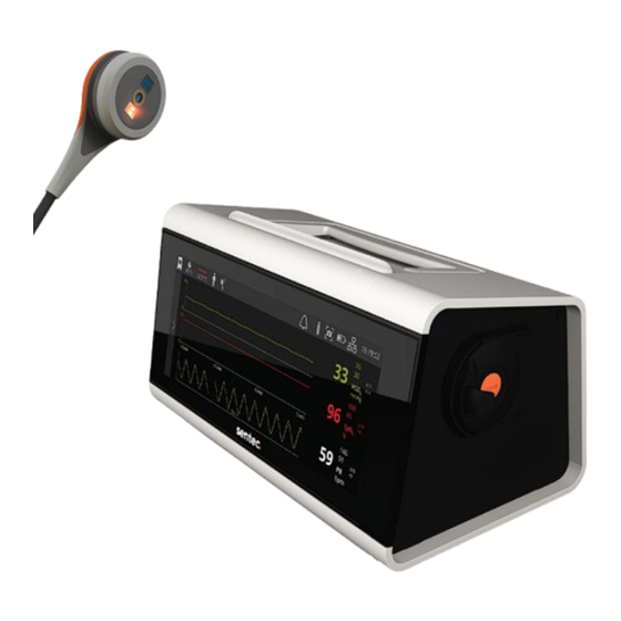
tCOM+ Front panel 1. LED Bar 2. Touchscreen 3. Handle Side panel – left Side panel – right 7. Docking Station 4. Gas Bottle 5. DATA/SERVICE USB Port (USB C) 6. ON/OFF Button... -
Page 4: Back Panel
Back panel Cable Holder Slots Sensor Connection Port DC Power Connector Serial Data Port (RS-232) Isolated Connectivity Port (USB C) Network Port (LAN) Analog Output Port Battery Cover Speaker Touchscreen The tCOM+ touchscreen allows user interaction via fingertip/thumb movement, such as tapping icons, words, and symbols, e.g., to bring up or exit screens and to select or toggle options. -
Page 5: Warranty
Sentec AG are used, if the warranty seal on the lower side of the monitor is broken, or if instrument repairs are not carried out by Sentec service personnel. -
Page 6: Table Of Contents
1.4.1 Principles of Operations of Pulse Oximetry 1.4.2 Limitations of Pulse Oximetry 1.5 Sentec Transcutaneous Sensors 2 Setting up the Sentec Digital Monitoring System 2.1 Connect tCOM+ to AC Power 2.2 Battery Operation of the tCOM+ 2.3 Turning on the tCOM+ 2.4 Installation of the Calibration Gas Bottle... - Page 7 3.8.5.3 Heating Power Settings 3.8.5.4 Spot Check 48 3.8.5.5 PCO In-Vivo Correction 3.8.5.6 Severinghaus Correction Mode 3.9 Sensor Removal with Multi-Site Attachment Ring/Non-Adhesive Wrap 3.10 Sensor Removal with Ear Clip 3.11 Patient Data Management 3.12 Sensor Calibration and Storage 3.13 Changing the Sensor Membrane 4 Troubleshooting/Preventive Maintenance 4.1 Routine checks, service, and maintenance procedures 4.1.1 Cleaning/disinfection...
- Page 8 9.4 Pulse Oximetry 9.4.1 Oxygen Saturation (SpO 9.4.2 Pulse Rate (PR) 9.4.3 Function Test SpO + PR 9.4.4 A values using Sentec TC Sensors 9.5 Power Supply 9.6 Alarm System 9.7 Sensors 10 Packaging & packaging damage 11 Waste disposal 12 Incident Reporting 12.1 Cybersecurity Vulnerability and Incident Reporting...
-
Page 9: The Sentec Digital Monitoring System (Sdms/System)
PC-based software – is indicated for non-invasive patient monitoring of oxygenation and ventilation. The Sentec Digital Monitoring System is for prescription use only. Devices are non-sterile and non-invasive. The monitor is not in direct contact with the patient during monitoring. The V-Sign™... -
Page 10: Intended Purpose Of The Tcom
J.W. Severinghaus. The ‘Severinghaus Equation’ first corrects PcCO measured at the sensor temperature (T) to 37 °C by using an anaerobic temperature factor (A) and then subtracts an estimate of the local ‘Metabolic Offset’ (M). Sentec Transcutaneous Monitoring 10... -
Page 11: Limitations Of Tcpco
(unless explicitly stated otherwise), ‘tcPO ’ is displayed/labeled as ‘PO ’. The recommended (and default) ‘Sensor Temperature’ and ‘Site Time’ for Sentec Transcutaneous Sensors depend on the selected patient type and the enabled parameters as summarized in the following table: RECOMMENDED SENSOR... -
Page 12: Pulse Oximetry
Note: The Sentec Monitors are not intended for diagnosis; they are intended only as an adjunct in patient assessment. They must be used in conjunction with clinical signs and symptoms. The Sentec monitors are transcutaneous blood gas monitors and not blood gas analyzers. -
Page 13: Limitations Of Pulse Oximetry
2-wavelength, reflectance pulse oximetry with the components needed to measure and – when using OxiVenT™ Sensors – PO Note: Throughout this manual, the term ‘Sentec TC Sensor’ refers to Sentec sensors providing transcutaneous blood gas measurements (i.e., V-Sign™ Sensor 2 and OxiVenT™ Sensor). -
Page 14: Setting Up The Sentec Digital Monitoring System
24 hours during one of the ongoing PCO calibrations. To achieve local arterialization of the skin tissue at the measurement site, Sentec TC Sensors are operated at a constant recommended sensor temperature of 41 °C in neonatal and 42 °C in adult/pediatric patients if PO is disabled and 43 °C in neonatal and... -
Page 15: Connect Tcom+ To Ac Power
WARNING: The use of accessories, sensors, and cables other than those specified by Sentec, may result in increased emission and/or decreased immunity and inaccurate readings of the monitor. WARNING: Do not attach accessories of the Roll Stand in any position that might cause it to tip over and possibly fall on the patient. -
Page 16: Battery Operation Of The Tcom
AC power, wiped dry externally, allowed to dry thoroughly, and inspected by qualified service personnel before further use. WARNING: Use only power unit provided by Sentec. WARNING: Interference is possible when a sensitive device (ECG, EEG) is connected to the patient at the same time in home healthcare environments (due to class II power supply without functional earth). -
Page 17: Installation Of The Calibration Gas Bottle
CAUTION: Do not use the monitor if an internal problem was detected during the POST (display of the message ‘failed’ with corresponding error code on POST screen). Instead, contact Sentec service personnel or your local Sentec representative. CAUTION: Ensure that the fan of the monitor is clear of any obstructions and that the monitor is in a well-ventilated dust-free environment. -
Page 18: Connection/Disconnection Of Sensor Adapter Cable
CAUTION: Do not use expired gas bottles or gas bottles from manufacturers other than Sentec. The use of non-Sentec gas bottles may damage the Docking Station. Improper calibration gas mixtures will result in incorrect sensor calibrations and subsequently result in inaccurate PCO and/or PO data. -
Page 19: Affixing Tilting Feet And Adjusting The Display Angle
Shut Down Menu Screen. Note: In case of any problem that prevents the monitor from being switched off, the tCOM+ can also be forced to switch off by pressing the ON/OFF button for more than 6 seconds. Sentec Transcutaneous Monitoring 19... -
Page 20: Patient Monitoring With The Tcom
Ensure that the sensor is clean before visually checking it. If necessary, carefully wipe off any residue from the sensor’s surface (including membrane, housing, and cable) with 70% isopropanol or another approved cleaning agent (refer to sentec.com/ifu). Checking a V-Sign™ Sensor (see image 1 above): Look for a smooth, clear membrane without scratches or air bubbles. -
Page 21: Patients With Potentially Impaired Skin Perfusion Or Characteristics Requiring Special Attention
• there is any visible damage to the sensor housing or cable. Replace the sensor. If in doubt, contact qualified service personnel or your local Sentec representative regarding continued use or replacement of the sensor. CAUTION: Do not touch the delicate optical/glass components embedded in the sensor’s surface should the membrane be missing. -
Page 22: Patient Type And Selection Of Measurement Site / Sensor Attachment Accessory
Before selecting a measurement profile on the tCOM+, determine the patient type. There are various measurement sites and sensor attachment accessories, depending on patient and parameter type. Refer to the image below and the following page for additional (important) information. Sentec Transcutaneous Monitoring 22... - Page 23 Attachment Rings. Please refer to the Directions for Use for the Staysite™ Adhesive. WARNING: The measurement of SpO and PR with Sentec TC Sensors is only defined on sites specified in the images (3.3). Choose a profile where the parameters /PR are disabled on other measurement sites.
- Page 24 WARNING: Compatibility issues when using non-Sentec consumables / accessories. Use only equipment, accessories, disposables, or parts supplied or recommended by Sentec AG. Failure to comply may result in physical injury, inaccurate measurements, and/or damage to the device. CAUTION: Potential low correlation to arterial values when a lower range temperature is selected for the sensor.
-
Page 25: Checking And Adjusting Tcom+ Settings
To be able to continue, users must choose one of the profiles depicted. If the connected sensor is in the Docking Station, ‘Calibration in progress’ or ‘Ready for use’ is displayed in the center of the screen. Once sensor calibration is completed, the tCOM+ will display ‘Ready for use’. Sentec Transcutaneous Monitoring 25... -
Page 26: Menu Overview
To calibrate the sensor, confirm membrane change, Maintenance or perform a sensitivity test System Lists system-related information Information Trend Adjust trend ranges and time scale for enabled Settings parameters Step-by-step guides for the most common Tutorials application and maintenance procedures Sentec Transcutaneous Monitoring 26... -
Page 27: Profile Selection
This overview highlights the most relevant default settings which can be configured in the ‘Edit Profiles’ menu: tCOM+ PROFILE PARAMETER SETTINGS Care Setting Hospital Sleep / Home / Spot Check Patient Type Adult / Neonate Adult / Neonate Sentec Transcutaneous Monitoring 27... - Page 28 Sensor Temperature Neonate: 41 / 43 (if PO Adult Spot Check: 43.5 (°C) enabled) Neonate: 41 Adult: 12 Sleep / Home: 12 Max. Site Time (h) Neonate: 8 / 6 (if PO Spot Check: 0.5 enabled) Sentec Transcutaneous Monitoring 28...
-
Page 29: Temperature And Site Time
Profile Selection (3.4.3). 3.4.5 Temperature and Site Time To achieve local arterialization of the skin tissue at the measurement site, Sentec TC Sensors are operated at a sensor temperature higher than the body temperature. -
Page 30: Adult
37.0 ≤ T ≤ 41.5 12.0 0.5 – 12.0 37 – 44.5 °C Adult/ -Temperatures above 42.0 ≤ T ≤ 42.5 0.5 – 12.0 Pediatric 42.0 °C only if PCO enabled 43.0 ≤ T ≤ 43.5 0.5 – 8.0 Sentec Transcutaneous Monitoring 30... -
Page 31: Enabled)
‘Site Protection’ (SP, right part of arrow) states are depicted as follows: ‘Site Protection’ is only enabled (and depicted with a downward blue arrow) for sensor temperatures above 41 °C in adult profiles and 40 °C in neonatal profiles. Sentec Transcutaneous Monitoring 31... -
Page 32: Alarm Settings & Behavior
Sentec Transcutaneous Monitoring 32... - Page 33 PO high. The device ensures that auditory signals do not superpose and only outputs the highest priority acoustic signal. In addition to the audible alarm signals mentioned above, the tCOM+ provides the following auditory signals: Sentec Transcutaneous Monitoring 33...
- Page 34 Nevertheless, a Supervisor Alarm is an unusual event that indicates that the behavior of the monitor was not as intended. Please inform qualified service personnel or your local Sentec representative in case of such an event for further investigation. To prevent disturbing stable patients during overnight measurements, such as those taken in a sleep laboratory or home environment, the supervisor alarm is deactivated when the monitor volume is set to 0.
-
Page 35: Visual Alarm Signals
WARNING: If an alarm condition occurs while the auditory alarm signals are paused or permanently switched off, the only alarm indication will be visual (if Sleep Mode is not active), but no alarm tone will sound. Sentec Transcutaneous Monitoring 35... -
Page 36: Adjusting Alarm Limits
3.5 Sensor Application using a Multi-Site Attachment Ring Sentec offers multiple adhesion options to accommodate a wide range of patients and scenarios supporting patient comfort and clinical utility. Use the Multi-Site-Attachment Ring MARe-MI for sensor application on mature skin and the Multi-Site-Attachment Ring MARe-SF for application on sensitive skin. - Page 37 Do not swallow Contact Gel. Keep away from children. Avoid contact with eyes and injured skin. Do not use on patients who exhibit allergic reactions to one of the components. Use only approved Sentec Contact Gel. Sentec Transcutaneous Monitoring 37...
- Page 38 WARNING: Always select the measuring site carefully to avoid selecting a site with low perfusion or low signal quality, which can cause incorrect measurements. Sentec Transcutaneous Monitoring 38...
-
Page 39: Sensor Application Using An Ear Clip
‘Sensor Temperature’ and, as a safety precaution, would cause the monitor to switch off the Sentec TC Sensor. 3.6 Sensor Application using an Ear Clip Sentec’s Ear Clip EC-MI is intended to attach the Sentec sensors to the earlobe of the patient. It is recommended for patients with mature/intact skin. Note: To attach a Sentec TC Sensor with the Ear Clip, the earlobe should be large enough to cover the entire sensor membrane (dark surface of the sensor). - Page 40 Do not use on patients who exhibit allergic reactions to one of the components. Use only approved Sentec Contact Gel. Pull the earlobe with the Ear Clip in horizontal position. Move the sensor horizontally into place with the cable preferably pointing to the crown of the head.
-
Page 41: Sensor Application Using A Non-Adhesive Wrap
3.7 Sensor Application using a Non-Adhesive Wrap Sentec’s Non-Adhesive Wrap is intended to be wrapped around the thigh of neona- tal/preterm patients with very sensitive/ fragile skin. CAUTION: Before using a brand-new sensor, the sensor membrane must always be changed, see chapter 3.13. - Page 42 WARNING: Do not swallow Contact Gel. Keep away from children. Avoid contact with eyes and injured skin. Do not use on patients who exhibit allergic reactions. Use only approved Sentec Contact Gel. Sentec Transcutaneous Monitoring 42...
-
Page 43: Patient Monitoring
If SpO /PR are enabled, monitor’s algorithms typically will flag the PCO and PO readings to be unstable (displayed in grey) and the SpO and PR readings to be invalid (respective values Sentec Transcutaneous Monitoring 43... -
Page 44: Tc-Stabilization After Sensor Application Or 'Tc-Artifacts
Status Bar (in h) until either the selected ‘Site Time’ or – if PCO is enabled – the ‘Calibration Interval’ elapses (whichever occurs first). When the ‘Calibration Interval’ elapses before the selected ‘Site Time’, the ‘Available Monitoring Time’ Icon turns yellow, the message ‘Sensor calibration recommended’ is Sentec Transcutaneous Monitoring 44... -
Page 45: Quality Indicators For Measurement Parameters
For more details, refer to 3.8.5.2. Sentec Transcutaneous Monitoring 45... -
Page 46: Advanced Measurement Options
A parameter’s ∆x-value is displayed to the right of its online trend and corresponds to the difference between its current reading and its reading x minutes ago. x is called ‘Delta- Time’ and is adjustable between 1 and 120 minutes. The default value for ‘Delta-Time’ is 10 minutes. Sentec Transcutaneous Monitoring 46... -
Page 47: Heating Power Settings
´Baselines´. 3.8.5.3 Heating Power Settings Once a Sentec TC Sensor is stabilized on the skin in an environment with constant ambient temperature, the heating power required to maintain the sensor temperature depends to a small fraction on the local skin blood flow beneath the sensor site and, hence, heating power fluctuations may indicate changes in local skin blood flow. -
Page 48: Spot Check
The ‘PCO Vivo Correction’ should only be used when a systematic difference between the monitor’s PCO readings and PaCO is clearly established by several arterial blood gas measurements. Sentec Transcutaneous Monitoring 48... -
Page 49: Severinghaus Correction Mode
Remove the adhesive tape securing the sensor cable, if applicable. Place a finger on each side of the retainer ring and rotate the sensor towards the index finger. The index finger will act as a wedge and will disengage the sensor from the ring. Sentec Transcutaneous Monitoring 49... -
Page 50: Sensor Removal With Ear Clip
(message ‘Site time elapsed’ or ‘Calibrate sensor’). Note: For site inspection and/or calibration, the Ear Clip can remain on the same earlobe for up to 24 hours and may be reused for another sensor application. It is recommended Sentec Transcutaneous Monitoring 50... - Page 51 Docking Station for calibration and/or storage. Note: To maintain monitor readiness and minimize PCO drift potential, always keep the tCOM+ switched on and store the sensor in the Docking Station in between monitoring. Sentec Transcutaneous Monitoring 51...
-
Page 52: Patient Data Management
Remove the USB stick from the USB port Sentec’s V-STATS software may be used for tCOM+ data analysis and reporting. V-STATS is available for download on sentec.com/download-v-stats/. Import the tCOM+ measurement files into V-STATS following the instructions below: Select the V-STATS menu ‘File’... -
Page 53: Sensor Calibration And Storage
‘---’). Good to know! ‘Calibration Intervals’ for Sentec TC Sensors can be set up to 12 hours. Once the ‘Calibration Interval’ has elapsed, sensor calibration is recommended (message ‘Sensor calibration recommended’) and monitoring is possible for another 4 to 6 hours with marked as ‘questionable’. - Page 54 When the tCOM+ and the connected sensor are not in use, Sentec recommends wrapping the sensor cable around the detachable cable holders located at the back of the monitor, thus avoiding entanglement or cable damage.
-
Page 55: Changing The Sensor Membrane
3.13 Changing the Sensor Membrane The membrane of a Sentec TC Sensor must be changed if the ‘Membrane Change Interval’ has elapsed. In this case, the tCOM+ displays the message ‘Change sensor membrane’, triggers a low priority alarm, marks PCO... - Page 56 Confirming Membrane Change on tCOM+ Once the inspection of the sensor membrane is completed successfully, confirm the membrane change on the monitor (menu ‘Sensor Maintenance’. Note: The membrane timer only resets if you confirm the membrane change on the monitor. Sentec Transcutaneous Monitoring 56...
-
Page 57: Troubleshooting/Preventive Maintenance
CAUTION: The cover must only be removed by Sentec service personnel. There are no user-serviceable parts inside the tCOM+. To guarantee continuous performance, reliability, and safety of the system, the... -
Page 58: Cleaning/Disinfection
Recommended cleaning/disinfection procedures for Sentec TC Sensors For cleaning and/or disinfection of Sentec TC Sensors, use 70% Isopropanol or an approved cleaning agent listed in HB-010143-Cleaning –and Disinfection Agents. Recommended cleaning/disinfection procedures for the tCOM+ Sentec recommends cleaning the monitor weekly using a wipe moistened with 70% Isopropanol or an approved cleaning agent listed in HB-010143-Cleaning –and... -
Page 59: Sensor Clean And Soak
4.1.2 Sensor Clean and Soak To guarantee continuous performance of Sentec TC Sensors, a clean and soak procedure should be performed once every quarter: Sentec Transcutaneous Monitoring 59... -
Page 60: Troubleshooting During Patient Monitoring
OxiVenT™ Sensor (3.1). If the ring around the pH-glass is broken, parts of it are missing, the brown color is lost, or the ring has a metallic luster, then replace the sensor with a new Sentec TC Sensor (3.1, 3.13). - Page 61 An ‘Extended Calibration’ is initiated if a regular sensor calibration could not be finished successfully within 14 minutes due to an unstable sensor. Note: Refer to the Status Messages ‘Extended Calibration’, ‘PCO slow’ and ‘Sensor Problem 11: Calibration Failed’. Sentec Transcutaneous Monitoring 61...
- Page 62 This message is only generated if SpO /PR is enabled, LED failure alarm and a Sentec TC Sensor is in the Docking Station. Note: ‘SP20: LED Failure’ resets upon restarting of the tCOM+ or if the problem does not reoccur when inserting the sensor into the Docking Station.
- Page 63 Do not use the sensor if this message cannot be reset by sensor alarm restarting the tCOM+. Instead, contact qualified service temperature personnel or your local Sentec representative. Note: Also, refer to messages ‘Sensor problem 38: High sensor temperature’, ‘Sensor problem 42: High sensor temperature’, and ‘Sensor fault 43 High sensor temperature’.
- Page 64 Sensor fault SF61 priority interrupts all power to the sensor. Do not use this sensor. alarm Contact qualified service personnel or your local Sentec representative. The tCOM+ detects that the LED of the connected OxiVenT™ Sensor’s PO module is defective. PO is marked as invalid, irrespective of sensor position.
-
Page 65: Technical Status Messages And Status Codes
Do not use the tCOM+ if MFxx priority restarting does not reset the message. Instead, contact alarm qualified service personnel or your local Sentec representative. Note: Prior to sending the tCOM+ to repair, it is possible to export trend data. - Page 66 An event triggering a so-called ‘Initial Calibration’ Calibrate Low priority occurred and sensor calibration therefore is sensor alarm mandatory. Insert the sensor into the Docking Station. Calibration will start automatically. Sentec Transcutaneous Monitoring 66...
- Page 67 This message will also appear if the sensor temperature deviates by more than 2 °C from the Sensor Temperature for more than 10 minutes. Note: This message will also appear if the ‘Enforced Sensor-On-Patient Mode’ is active and PCO2 is below Sentec Transcutaneous Monitoring 67...
- Page 68 Docking Station. Note: The ‘Gas Icon’ appears over a cyan background if the gas bottle is empty and yellow if the remaining capacity is < 10%. Sentec Transcutaneous Monitoring 68...
- Page 69 Information light range. Note: This message only appears if SpO /PR are enabled, and ‘Sensor-On-Patient’ is detected. Note: , PR, and PI are marked as questionable when high ambient light levels are detected. Sentec Transcutaneous Monitoring 69...
- Page 70 PO is marked invalid accompanied by a low priority alarm. The connected sensor is not compatible with the tCOM+ or the Sentec Identification Code stored in its Incompatible Low priority memory is not readable or corrupt.
- Page 71 ‘PO artifact’, the low priority alarm ‘Check sensor application’ is triggered. Note: Ambient air (intermittently) penetrating between the sensor surface and the skin, typically resulting in fast PO changes, is the most frequent Sentec Transcutaneous Monitoring 71...
- Page 72 Unless the ‘Site Time’ has expired, the ‘Remaining Monitoring Time Icon’ is highlighted yellow inside if calibration is recommended. Note: If the Status Code ‘CS’ is output while the sensor is in the Docking Station, the sensor is not (yet) calibrated. Sentec Transcutaneous Monitoring 72...
- Page 73 ‘Sensor off patient’ alarm patient alarm condition, reset the Site Timer to the selected ‘Site Time’, and - if reduced by Site Protection - reactivate sensor heating. The measurement screen will remain active. Sentec Transcutaneous Monitoring 73...
- Page 74 ‘Sensor off patient’ in the Status Bar or insert the Sentec TC Sensor into the Docking Station. This message is displayed whenever the tCOM+ detects a weak pulsatile signal independently from its severity or the impact on SpO , PR or PI values.
- Page 75 After the POST screen, a low priority alarm is triggered and a yellow information text appears, instructing the operator to contact a Sentec service technician to change the clock battery as soon as possible and that meanwhile the tCOM+ may be used, provided the monitor’s date/time is set to the...
-
Page 76: Service
Battery Note: Use only accessories and spare parts supplied or recommended by Sentec AG. Do not perform other service and repair activities than specified and described by Sentec AG. Failure to comply may result in physical injury, inaccurate measurements, and/or damage to the device. -
Page 77: Replacing The Docking Station Gasket
Do not let the battery discharge fully. Recharge it at least every 6 months. Perform the following steps to replace the battery: Open the battery cover on the back side of the monitor by means of a torque screwdriver. Remove the old battery. Sentec Transcutaneous Monitoring 77... -
Page 78: Software Update
Ensure to check the software version for accuracy in the System Information menu once the software update is completed. Note: Software updates must be reported to Sentec by using the Repair and Reporting Form, available on sentec.com/ifu, to ensure traceability. 5 Further Applications of the tCOM+ 5.1 Home use... -
Page 79: Qualifications / Training Requirements For Home Use
Setting up the system and configuring the tCOM+ shall only be performed by an instructed person from a homecare provider. This instructed person must have received the appropriate training by a Sentec representative or Sentec authorized person. -
Page 80: Data Communication
‘SDM Compatibility Mode’ and an associated Compatibility Version. This mode ensures compatibility with legacy connectivity integrations (e.g., with Patient Monitoring Systems, Patient Data Management Systems, PG/PSG Systems or Ventilators) that were developed for the tCOM+ predecessor device, the Sentec Digital Monitor. Please refer to https://www.sentec.com/transcutaneous-connectivity-overview/ for more information on Interface Options for the tCOM+. - Page 81 To interface the tCOM+ with a polygraphic or polysomnographic system, select the appropriate cable from the connectivity overview on Sentec´s webpage and then perform the following steps: Connect the PSG Adapter Cable to the tCOM+ Analog Output Port Connect the free end(s) of the PSG Adapter Cable to the PG-/PSG-System.
-
Page 82: Data/Service Usb Port
The following settings are recommended when the tCOM+ is included in a wireless network: • Use dedicated Wi-Fi channel, ensure enough separation of adjacent channels • Avoid disturbers in the same or adjacent Wi-Fi channel Sentec Transcutaneous Monitoring 82... - Page 83 Note: Changes or modifications made to this equipment not expressly approved by Sentec may void the FCC authorization to operate this equipment. This equipment has been tested and found to comply with the limits for a Class B digital device, pursuant to part 15 of the FCC Rules. These limits are designed to provide reasonable protection against harmful interference in a residential installation.
-
Page 84: Cybersecurity
In addition, security related incidents are displayed to the user by the tCOM+ monitor as technical alarms and are logged. In case that there is a concern that an external party is trying to connect to or interfere with the monitor, stop using the tCOM+ and contact the local Sentec representative immediately. 6.3.1.1 Firewall Per factory default, all network interfaces of the tCOM+ are protected by a firewall and no service is accessible. -
Page 85: Vpn
Wi-Fi (e.g., for legacy connectivity applications). Furthermore, single ports in the firewall can be opened individually for LAN, Wi-Fi, and VPN to give access to the available services of the tCOM+, such as Sentec Discovery Protocol (SDP), Sentec Monitor Interface (SMI) or SSH (only available for Sentec-Service). -
Page 86: Encrypted Communication
6.3.1.3 Encrypted communication To secure interfaces where no VPN technology is applicable, such as the Serial Data Port (RS-232), and to offer more flexibility for connectivity solutions, Sentec also supports the encryption of the Sentec Monitor Interface (SMI) directly with the authenticated encryption and hashing algorithms “ASCON”. -
Page 87: Minimum Hardware And Software Requirements
Capacity (new fully charged battery): up to 4 hours (if Sleep Mode=OFF) Charging Time: approx. 4 hours Environmental Transport/ storage temperature: 0 to +50 °C (32 to 122 °F) Transport/ storage humidity: 10 to 90% non-condensing Operating temperature: +5 to +40 °C (41 to 104 °F) Sentec Transcutaneous Monitoring 87... -
Page 88: Tcpco
+/- 5 mmHg in the range of 0 mmHg – 160 mmHg* tcPO LED characteristics Wavelengths: green-cyan colored Energy: < 5 mW Note: This information may be especially useful to clinicians. *Essential Performance according to IEC 60601-1 Sentec Transcutaneous Monitoring 88... -
Page 89: Pulse Oximetry
Nellcor). The SpO and PR reading should be within ± 3% SpO and ± 3 bpm, respectively. 9.4.4 A values using Sentec TC Sensors The following table shows A values measured using the V-Sign™ Sensor 2 with the tCOM+, whereas SpO... -
Page 90: Power Supply
Class II with Adapter North functional earth Hospital Use GlobTek America connection R-NA-3(R) Adapter UK GlobTek R-UK-3(R) Adapter GlobTek Australia/NZ R-SAA-3(R) Power supply GlobTek Class II without GTM96300-3614.5-2.5-R2 functional earth Home Use Output Rating: 12V / 36W connection Sentec Transcutaneous Monitoring 90... -
Page 91: Alarm System
The response to changes in the < 75 sec (V-Sign™ Sensor 2) low/high carbon dioxide pressure in the skin at < 80 sec (OxiVenT™ Sensor) alarm a specific measurement site depends on the selected sensor temperature Sentec Transcutaneous Monitoring 91... - Page 92 Note: If ‘Sensor problem 74’ (PO slow) occurs, a low priority alarm sounds, the Status Message ‘Sensor problem 74: PO Calibration Failed’ is displayed and sensor calibration is inhibited/aborted. PO values are subsequently marked as invalid. Sentec Transcutaneous Monitoring 92...
- Page 93 With the exception of the following alarm conditions, alarm condition delays of all technical alarm conditions are < 5 seconds: Alarm Condition Delays > 5 sec for technical alarm conditions Technical Alarm Condition Typical Alarm Condition Delay Sensor off patient V-Sign™ Sensor, OxiVenT™ Sensor: < 10 sec Sentec Transcutaneous Monitoring 93...
-
Page 94: Sensors
In such a case, return the tCOM+ to Sentec. Items must be shipped in the original packaging or in other packaging providing the same degree of protection. -
Page 95: Incident Reporting
By recycling materials or other forms of utilizing old devices, you are making an important contribution to protecting our environment. tCOM+ Return the tCOM+ to your local Sentec representative or dispose of it according to local regulations. Use original packaging or other packaging providing the same degree of protection for shipping. -
Page 96: Cybersecurity Vulnerability And Incident Reporting
12.1 Cybersecurity Vulnerability and Incident Reporting If a cybersecurity incident has occurred or you have detected a cybersecurity vulnerability in our product(s), please report it to us using the dedicated link on Sentec’s website: https://www.sentec.com/quality/. presented “Link Vulnerability Reporting” will direct you to the MedISAO (Information Sharing and Analysis Organization) portal, which collects vulnerability data of Sentec products. -
Page 97: Appendix
Pulse rate Relative Heating Power Remote monitoring interrupted Arterial oxygen saturation tCOM+ Sentec Patient Monitor SDMS Sentec Digital Monitoring System Functional oxygen saturation of arterial hemoglobin as measured with a pulse oximeter Transcutaneous tCOM+ Transcutaneous carbon dioxide and oxygen monitor tcPCO Transcutaneous carbon dioxide partial pressure, i.e., an estimate of... -
Page 98: List Of Components
13.2 List of Components The Sentec Digital Monitoring System comprises the following components: Product Environmental/ Expected useful (Brand) Storage Description Intended Purpose Variants Reusable life Name conditions Transport/storag The Sentec patient monitor, model e temperature: tCOM+, is a portable stand-alone patient 0 –... - Page 99 15 – 26°C Sensor oximetry the use of OxiVenT™ Sensor is indicated Transport/ store sensor for tcPCO and tcPO monitoring only. sensor with tcPO monitoring is contraindicated for membrane and patients under gas anesthesia. protected from light/ radiation. Sentec Transcutaneous Monitoring 99...
- Page 100 Sensor /optoelectronic Long: 0 – 50 °C connect digital Sentec sensors (V-Sign™ 103421 Adapter components 250 cm 7 years Sensor 2, OxiVenT™ Sensor) to the Sentec Transport/storag Cable (LEDs) and to tCOM+. 103422 Extra e humidity: heat the Long: 10 – 95% sensor.
- Page 101 Variants Reusable Storage life Name conditions Sentec’s Ear Clip, model EC-MI, is intended to attach the Sentec sensors to Reusing the Ear the earlobe of the patient, recommended Clip may cause: Single use for patients with mature/intact skin. sensor applica-...
- Page 102 Temperature: – 2 Attachm model MARe-SF, are intended to attach cross-infection commended 7 °C MARe- ent Ring the Sentec Sensors to conventional for adult, 1.5 years - loss of Easy for measurement sites, recommended for Humidity: pediatric and functionality...
- Page 103 Description Intended Purpose Variants Reusable Storage life Name conditions Single-use Sentec’s Staysite™ Adhesive for MAR, Reusing the SA- adhesive for model SA-MAR, is an optional, single-use MAR may cause: Multi-Site adhesive which is indicated for use with Staysite Attachment Multi-Site Attachment Rings, models ™...
- Page 104 Changer prior incorrect reuse. measurements Yes, for about Calibration gas The Calibration Gas serves as calibration two months after Docking gas for the Sentec transcutaneous opening, Station, sensors that monitor tcPCO and/or depending on Temperature: cylinder of 0.2 l tcPO (V-Sign™...
- Page 105 Sentec transcutaneous sensors. Contact Gel makes direct patient contact (intact skin, prolonged exposure <30 days). Do not use Contact Gel if it is Contact gel for Avoid contact with injured skin.
-
Page 106: Interferences With Other Devices
Identification), and electromagnetic security systems such as anti-theft/electronic article surveillance systems, metal detectors. Note that the presence of RFID devices may not be obvious. If such interference is suspected, reposition the equipment, if possible, to maximize distances. Sentec Transcutaneous Monitoring 106... -
Page 107: Means Of Isolation (Mains)
Use-by date Indicates the date after which the medical device is not to be used. Period after Identifies the useful lifetime of a product after its opening package has been opened for the first time (M=months). Sentec Transcutaneous Monitoring 107... - Page 108 Mandatory Indicates that the instruction manual must be read action: Refer to in order to ensure safety. instruction manual General Read all warnings and precautions in instructions for warning sign use. WARNING Indicates WARNING accompanying documentation. Sentec Transcutaneous Monitoring 108...
- Page 109 Proof Type BF Defibrillation-proof, Type BF applied part Ingress Degree of protection against harmful ingress of Protection water Bluetooth Device is equipped with Bluetooth functionality. RFID tag, indicate presence RFID general incorporated within the packaging, container, or Sentec Transcutaneous Monitoring 109...
- Page 110 Indicates that the product complies with the requirements of the relevant EU Directives and Regulations as outlined in the EU Declaration of Conformity. If applicable, the 4-digit Notified Body number is added near or below the CE symbol. Sentec Transcutaneous Monitoring 110...
-
Page 111: User Interface Icons
Protection’ is enabled, a red rightward arrow if it is disabled. The sensor temperature is marked blue if ‘Site Protection’ has reduced the sensor temperature and red if the temperature surveillance detected a sensor temperature-related problem. ‘Initial Heating’ - on ‘Site Protection’ - off Sentec Transcutaneous Monitoring 111... - Page 112 Tapping on the icon will prompt a pop-up message indicating the filling state in %. Yellow inner part: filling state 10% or less Cyan background: gas bottle empty Screenshot Battery – view battery status and capacity Cyan background: battery status low Yellow background: battery status critical Sentec Transcutaneous Monitoring 112...
- Page 113 AC power, charging not connected, charged < 75 % LAN connected /disconnected Bluetooth connected/disconnected Wi-Fi connected/disconnected Sentec Transcutaneous Monitoring 113...
-
Page 114: Detailed Spo
(3 light, 4 light-medium, 2 medium, 3 dark) were included in the analysis. The subjects were between 23 and 29 years old. Detailed plots for SpO accuracy of the V-Sign™ Sensor 2 per individual measuring site are given as follows: Sentec Transcutaneous Monitoring 114... - Page 115 Sentec Transcutaneous Monitoring 115...
- Page 116 Sentec Transcutaneous Monitoring 116...
-
Page 117: Oxivent™ Sensor
(5 light, 5 medium, 2 dark) were included in the analysis. The subjects were between 23 and 34 years old. Detailed plots for SpO accuracy of the OxiVenT™ Sensor per individual measuring site are given below: Sentec Transcutaneous Monitoring 117... -
Page 118: Pigmentation Dependence Of Spo
13.7.3 Pigmentation dependence of SpO Sentec is aware that the current pulse oximeter technique based on two measuring wavelengths is affected by skin pigmentation within the absorption path. To review such potential effects in Sentec’s own pulse oximeter devices, data from controlled desaturation studies were pooled and analyzed for racial bias. -
Page 119: Electromagnetic Emissions
In conclusion, a small racial bias in pulse oximetry for certain application sites could be observed within this data set. Most of the deviations are within Sentec’s claims of accuracy, however, and all deviations are within FDA’s limits of accuracy. - Page 120 5.15 GHz to 5.35 GHz (Ch 36/40/44/48/52/56/60/64) 5.47 GHz to 5.725 GHz (Ch 100/104/108/112/116/132/136/140) 5.725 GHz to 5.85 GHz (Ch 149/153/157/161/165) 2.4 GHz Bluetooth 5.2 7.9 mW Bluetooth 2.4 GHz – 2.4835 GHz 13.56 MHz ISO/IEC 15693 100 mW Sentec Transcutaneous Monitoring 120...
-
Page 121: Electromagnetic Immunity
Portable and mobile RF communications equipment should be used no closer to any part of the SDMS, including cables, than the recommended separation distance d calculated from the equation applicable to the frequency of the transmitter. Sentec Transcutaneous Monitoring 121... - Page 122 217Hz 800 - Pulse 800/900, modulation TETRA 800, 18Hz iDEN 820, CDMA 850, LTE Bans 5 1720 1700 - GSM 1800, Pulse 1990 CDMA 1900, modulation 1845 GSM 1900, 217Hz DECT, LTE 1970 Band 1,3, Sentec Transcutaneous Monitoring 122...
-
Page 123: Compliance
ISO 14971 (risk management), IEC 62366 (usability engineering), IEC 62304 (software in medical devices), ISO 10993-1 (biocompatibility), ISO 20417 (information supplied by manufacturers), ISO 15223-1 and -2 (symbols). This product complies with the requirements of the Medical Device Regulation (EU) 2017/745. Sentec Transcutaneous Monitoring 123... - Page 124 Sentec AG Ringstrasse 39 4106 Therwil Switzerland Date of release: 2024-06 www.sentec.com HBQ-179-V8...
Need help?
Do you have a question about the tCOM+ and is the answer not in the manual?
Questions and answers