Table of Contents
Advertisement
Advertisement
Table of Contents

Related Manuals for Sentec IPV 1


Summary of Contents for Sentec IPV 1
- Page 1 IPV® 1 System Instruction Manual...
- Page 2 The contents of this document may not be reproduced in any form or communicated to any third party without the prior written consent of Percussionaire® or Sentec. While every effort is made to ensure the correctness of the information provided in this document, neither Percussionaire®...
-
Page 3: Table Of Contents
Table of Contents 1: Introduction..............................1 About This Instruction Manual ........................1 Related Documents and Resources ......................1 Glossary of Symbols ............................2 Safety Information ............................3 Warnings ................................4 Precautions ..............................5 Technical Assistance ............................5 2: Intended Use ..............................6 Intended Purpose ..............................6 Intended Use Environment ...........................6 Intended User Profile ............................6 Indications for Use ............................6 Expected Clinical Benefits of IPV®... - Page 4 8: Prepare for Patient-Airway Connection ..................26 9: Administer IPV® Therapy ........................26 10: Cleaning and Maintenance Protocol ..................28 Digital Display ............................28 Stand Assembly............................28 Breathing Circuit - Phasitron® 5 UC ....................29 Phasitron® 5 UC Breathing Circuit Cleaning Process ...............30 11: Troubleshooting ...........................31 12: Service ................................31 IPV®...
-
Page 5: 1: Introduction
• Related documents and additional resources • Symbol definitions • Safety information, including warnings and cautions • Technical assistance information Related Documents and Resources The current version of this manual, specifications, clinical studies, and additional information is available at: Customerservice.us@sentec.com... -
Page 6: Glossary Of Symbols
Glossary of Symbols The table below summarizes symbols that may be used on the IPV® 1 (including all its related parts), on the packaging, and in the associated documentation. These symbols indicate informa- tion essential for proper use; the order of their appearance is not prioritized. Symbol Name Description... -
Page 7: Safety Information
Symbol Name Description Atmospheric pressure Indicates the atmospheric pressure limits limitation to which the medical device can be safely exposed. Single patient - Indicates a medical device that may be multiple use used multiple times (multiple procedures) on a single patient. Consult instructions Indicates the need for the user to consult for use... -
Page 8: Warnings
Warnings A WARNING indicates the possibility of injury, death, or other serious adverse reaction associated with the use or misuse of the device. General Warnings • Before use, read the instruction manual. • The IPV® 1 system shall not be used as a life support device. Supplemental oxygen must be prescribed for patients for whom it is indicated, and the O2 saturations should be monitored. -
Page 9: Precautions
Always check the incoming air/oxygen pressure settings before Pressure Settings connecting to the IPV® 1 device. Technical Assistance For technical information and assistance, to request service, or to order parts, use one of the following methods of contact: • Telephone: Technical service at 1-877-425-8746. • Email: Customerservice.us@sentec.com... -
Page 10: 2: Intended Use
2: Intended Use The IPV® 1 system is an active (it exchanges kinetic energy) medical device used in the field of respiratory medicine to provide Airway Clearance Therapy (ACT). The IPV® 1 control unit is a reusable driver intended to be used exclusively with the single-patient Phasitron®... -
Page 11: Contraindications
The IPV® 1 system is indicated to provide IPV® as a form of airway clearance therapy. During operation, the system provides a continuous, dense aerosol mist to reduce the adhesive and cohesive forces of retained airway secretions. Contraindications • Untreated tension pneumothorax •... -
Page 12: 3: Principles Of Operation
3: Principles of Operation The IPV® 1 system is a device that provides IPV® as a form of airway clearance therapy. During operation, the system provides continuous dense aerosol mist to reduce the adhesive and cohesive forces of retained airway secretions. IPV® provides a “Pulsatile Flow”... -
Page 13: 4: Description
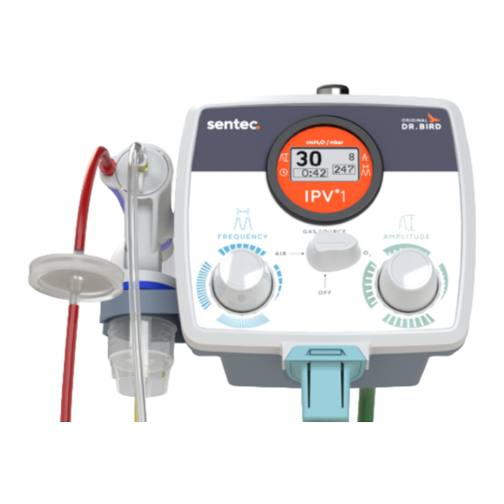
4: Description IPV® 1 System IPV® 1 Phasitron® 5 Front Panel 1. Digital Display 2. AMPLITUDE Adjustment Knob 3. GAS SOURCE Selector Knob 4. Breathing Circuit Connector 5. FREQUENCY Adjustment Knob 6. Phasitron® 5 UC Holder... -
Page 14: Control Functions
Control Functions Control Functions FREQUENCY determines the rate of high-frequency percussive pulses delivered to the patient. AMPLITUDE determines the pressure delivered to the patient. GAS SOURCE selects air or oxygen, or turns IPV® 1 off to stop therapy. Digital Display reads and displays Mean Airway Pressure (MAP), Pulse Frequency Rate, Usage Time, and Pulse Amplitude. -
Page 15: Back Panel
Back Panel 1. Pole Clamp 2. Phasitron® 5 3. Air Connector 4. Bleed Vent 5. Oxygen Connector Blended Gas/Air Connection The IPV® 1 connects to hospital single gas source or blended gas. Single or dual air/oxygen gas connections are standard. CAUTION: Bleed must remain unrestricted. -
Page 16: 5: Digital Display
5: Digital Display A digital display found on the front panel of the IPV® 1 device provides feedback of the patient proximal airway pressures, pulse frequency, and elapsed treatment time. The display has six different operating modes: POST, Wake, Active, Report, Sleep, and Fault. Note: The display will not awaken until feed- back from proximal line on the Phasitron®... -
Page 17: Wake Mode
Wake Mode To wake up the display, ensure the IPV® 1 pressure is greater than 7 cmH₂O/hPa at the Phasitron® patient-delivery port for more than 1 second. The display remains on for the first 15 seconds, showing the bar-graph timer. If usage is stopped within 12 seconds, the display enters Report mode. -
Page 18: Report Mode
Report Mode The Session Timer and the Total Usage Timer (A) are displayed for 2 seconds, followed by the System Information Page (B) for 2 seconds, alternating. The alternating page display continues for 5 minutes, or until usage resumes and the display enters Active Mode. During the 5-minute period, a horizontal bar graph indicates the time by moving from left to right at a fixed rate. -
Page 19: Fault Mode
Fault Mode In Fault mode, the display will show an error message on the display stating, “Contact Factory for Service. ” The displayed information includes the software revision, digital display serial number, the total usage time, and an error code for the exclusive use of the factory. -
Page 20: Digital Display - Setup
Digital Display - Setup When setting up the IPV® 1 device for the first time, the digital display must be removed to access the battery-disconnect tabs for removal. NOTE: When the display powers on for the first time, it will ensure the correct atmospheric pressure calibration at startup. -
Page 21: 6: Setup
6: Setup IPV® Mounted to Standard Pole Stand Roll Stand Assembly The IPV® 1 mounts onto a standard 0.75- to 1.5-inch (19 mm to 38 mm) hospital pole stand. -
Page 22: Attaching Ipv® 1 To Stand
Attaching IPV® 1 to Stand To mount device onto pole, open clamp. Use adjuster nut to set pole thickness. Close and lock clamp. -
Page 23: Breathing Circuit - Phasitron® 5 Uc
Breathing Circuit - Phasitron ® 5 UC The patented Phasitron® 5 uses a unique venturi as a “clutch” mechanism to protect the lung from overpressure. By automatically adjusting to the resistance of the lung, the Phasitron® 5 precisely and safely delivers the optimal amount and flow of air required by the alveolar space. -
Page 24: Breathing Circuit - Phasitron® 5 Uc - Components
Breathing Circuit - Phasitron® 5 UC - Components Corrugated Tubing Exhalation Port Safety Valve Entrainment Port Spring O-ring Venturi Patient Port ® Phasitron 5 UC Conical Connector Housing Nebulizer Cap Mouthpiece Diaphragm Nebulizer Bowl Baffle WARNING: Only use Percussionaire® parts and accessories Type BF Single-patient use Breathing Circuit - Phasitron®... -
Page 25: Breathing Circuit - Connecting To The Ipv® 1
Breathing Circuit - Connecting to the IPV® 1 The Phasitron® 5 UC breathing circuit connects into the bottom of the IPV® 1 device. Connecting Tubing to Phasitron® 5 Connect yellow tubing quick-connect fitting to nebulizer bowl. NOTE: The tubing connectors will only fit onto the correct part Press red tubing onto conical connector at rear of Phasitron®... -
Page 26: Adding Liquid Solution
Adding Liquid Solution Twist nebulizer bowl to the left to open. Add liquid solution, e.g., saline or other diluent as directed by physician. Apply the lid and twist the nebulizer bowl to the right to close. -
Page 27: 7: Pre-Use Check
7: Pre-Use Check 1. Verify the GAS SOURCE knob in the “OFF“ position. 2. Connect the IPV® 1 to medical 50 psi oxygen or air gas supply. 3. Connect a Siemens®-style 1-liter ventilator test lung (A) to the Phasitron® 5 (B). 4. - Page 28 7. Rotate the FREQUENCY control knob fully counterclockwise. 8. Confirm frequency rate of 300 or above. NOTE: Displayed pressure and time are for illustrative purposes only. 9. Verify the mean airway pressure (MAP) indicated on the digital display is greater than 15 cmH₂O. NOTE: Displayed pulse amplitude pressure, time, and frequency are for illustrative purposes only.
- Page 29 12. Verify the mean airway pressure (MAP) indicated on the digital display is greater than 10 cmH₂O. NOTE: Displayed pulse amplitude pressure, time, and frequency are for illustrative purposes only. 13. Rotate the FREQUENCY control knob to the center, straight up position. 14.
-
Page 30: 8: Prepare For Patient-Airway Connection
8: Prepare for Patient-Airway Connection To prepare for patient-airway connection, complete the following steps: 1. Rotate AMPLITUDE control knob clockwise to stop (off). 2. Connect the IPV® 1 to 50 psi (3.4 bar) gas source. Ensure GAS SOURCE switch is switched to OFF. - Page 31 5. After the patient obtains the ability to prevent the leaking of percussive air deliveries from the nose and around the lips, the entire percussion rate range should be scanned by rotating the FREQUENCY control knob. This works to raise secretions from the bronchial airways.
-
Page 32: 10: Cleaning And Maintenance Protocol
10: Cleaning and Maintenance Protocol Always clean the controller between patients and when visibly soiled. Use only approved cleaning wipes (CaviWipe®) to wipe the controller and stand to remove excess soil. Use ad- ditional CaviWipes if needed to remove visible soil. A visual inspection should be performed to ensure soil has been removed. -
Page 33: Breathing Circuit - Phasitron® 5 Uc
We recommend testing cleaning solutions on a small, non-visible area of the mounting assembly to verify compatibility (will not damage stand). CAUTION: • Do not use strong chemicals or solvents such as acetone or trichloroethylene. • Do not use steel wool or other abrasive material. •... -
Page 34: Phasitron® 5 Uc Breathing Circuit Cleaning Process
4. Twist the white cap on the rear of the Phasitron® 5 to remove. 5. Remove the cap. 6. Remove the sliding venturi and spring from the Phasitron® 5 body. Phasitron® 5 UC Breathing Circuit Cleaning Process Thoroughly rinse each of the disassembled parts (except for tubing harness) under warm running tap water for approximately ten (10) seconds. -
Page 35: 11: Troubleshooting
11: Troubleshooting CAUTION: If you notice any unexplained changes in the performance of the IPV® 1 driver unit or Phasitron® 5 UC breathing circuit, e.g., if either device is making unusual sounds, or if either device is dropped or damaged in any way, discontinue use and contact authorized service personnel. -
Page 36: Service
If the IPV® 1 is not functioning as it should, if it makes unusual noises, or if there are any concerns about device performance or condition, immediately discontinue use. Contact customer service at Customerservice.us@sentec.com. Changing Display Module Batteries Displays a low battery indicator when battery capacity is nearing depletion. -
Page 37: 13: Limited Warranty
Any serious incident that has occurred in relation to the IPV® 1 system has to be reported to Sentec (regulatory.percussionaire@sentec.com) and/or to the competent authority of the country where the incident occurred. If unsure whether an incident is... -
Page 38: 14: Technical Specifications
14: Technical Specifications Dimensions (W x H x D) 23.79 cm x 18.31 cm x 17.53 cm (9.4" x 7.2" x 6.9") Weight 1.45 kg (3.2 lb) 18°C to 26°C (64.4°F to 78.8°F) Operating Range Storage and Transport -30°C to +70°C (-22°F to 158°F) Up to 75% relative humidity Operating: 700 to 1060 hPa Atmospheric Pressure... -
Page 39: 15: Glossary
15: Glossary Active Mode: the digital display actively measures the pressure, computes the parameters, and displays them on the display. The Active mode display metrics include pulse frequency rate and mean airway pressure. Amplitude: controls the operating pressure of the entire unit. Atelectasis/Atelectatic lung: a complete or partial collapse of the entire lung or area (lobe) of the lung. - Page 40 FRC (Functional Residual Capacity): the volume remaining in the lungs after a normal, passive exhalation. The FRC also represents the point of the breathing cycle where the lung tissue elastic recoil and chest wall outward expansion are balanced and equal. IPV®...
- Page 41 System Failure: when the digital display is in Fault mode, an error message is displayed stating “System Failure” and “Contact Factory for Service. ” The display stays in Fault mode until both batteries are removed. System Information Page: when the digital display is in Report mode, the System Information page is displayed for 2 seconds, alternating with the Session Timer.
- Page 42 This page intentionally left blank.
- Page 43 This page intentionally left blank.
- Page 44 M Percussionaire®, 130 McGhee Rd., Suite 109, Sandpoint, Idaho 83864 sentec.com +1.208.263.2549 P20174 Rev C...
Need help?
Do you have a question about the IPV 1 and is the answer not in the manual?
Questions and answers