GeKaMac PoWer MIG Series User Manual
Hide thumbs
Also See for PoWer MIG Series:
- User manual (75 pages) ,
- User manual (40 pages) ,
- User manual (30 pages)

Related Manuals for GeKaMac PoWer MIG Series


Summary of Contents for GeKaMac PoWer MIG Series
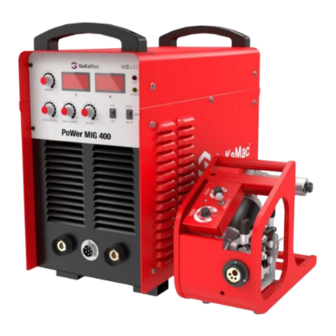
- Page 1 PoWerMIG 400 Users Manual Please Read and Understand This Manual Before Operating The Welding Machine www.gedik.com.tr...
- Page 2 This machine is for internal use only. It complies with the WEEE Directive. This machine has been designed in accordance with the EN 60974-1 and EN 60974-10 standards. The machine is safe when installation, operation, and maintenance are performed in accordance with the user manual and regulations.
-
Page 3: Dear Customer
Dear Customer This instruction manual will help you get to know your new machine. Read the manual carefully and you will soon be familiar with all the many great features of your new product. Meanwhile, please remember well safety rules and operate as instruction. If you treat your product carefully, this definitely helps to prolong its enduring quality and reliability–things which are both essential prerequisites for getting outstanding results. - Page 4 AT UYGUNLUK BEYANI EU DECLARATION OF CONFORMITY Bu uygunluk beyanı yalnızca /malatçının sorumluluğu altında düzenlen/r. Th#s declarat#on of conform#ty #s #ssued under the sole respons#b#l#ty of the manufacturer İstanbul, Turkey, 08.03.2024 İmalatçı / Manufacturer GEDİK KAYNAK SANAYİ ve TİCARET A.Ş. Ankara Cad.
-
Page 5: Safety Rules
Safety Rules “Danger” indicates an hazardous situation imminently.It will result in death or serious injury if people not avoided. “Warning!” indicates a hazardous situation potentially. It will result in death or serious injury if people not avoided. “Caution” indicates a hazardous situation possibly. It will result in slight or moderate injury if people not avoided. - Page 6 • If welding must be performed under electrically hazardous conditions as follow: in damp locations or wearing wet clothing; on metal structures such as floors, gratings, or scaffolds; when in cramped positions such as sitting, kneeling, or lying; or in occasion when there is a high risk of unavoidable or accidental contact with the work piece or ground.
- Page 7 Fumes and gases can be dangerous • Welding may generate fumes and gases which can be hazardous to your health if inhaled. • Keeping your head out of the fume when welding. If inside, ventilate the area at the arc to keep fumes and gases away from the breathing zone.
- Page 8 • Apply the correct fuses or circuit breakers. Do not oversize or bypass them. Cylinder can explode if damaged. • Pressure gas cylinders contain gas under high pressure. If damaged, a cylinder can explode. Since gas cylinders are part of the welding process normally, be sure to treat them carefully.
- Page 9 Moving parts can injure • Stay away from moving parts such as fans. • Stay away from pinch points such as drive rolls. • Keep all doors, panels, covers, and guards closed and securely in place. • Only qualified personnel should remove doors, panels, covers or guards for service and maintenance.
-
Page 10: Table Of Contents
CONTENT 1- GENERAL REMARKS ..............8 1-1 Power source features ..............8 1-2 Functional principle ................. 8 1-3 Output characteristics ..............9 1-4 Duty cycle ..................9 1-5 Applications .................. 10 1-6 Warning label ................10 2-VERSIONS BRIEFS ................ 11 3-BEFORE COMMISSIONING ............ -
Page 11: 1- General Remarks
1- GENERAL REMARKS This series welding machines apply IGBT soft switch inverter technology,the power source enjoys highly stable welding voltage against the fluctuation of power grid and arc length change. The internal control system achieves precise control of welding process to ensure optimal welding results. 1-1 Power source features Highlights as follows: - Enjoy reasonable static characteristic and sound dynamic characteristic... -
Page 12: Output Characteristics
1-3 Output characteristics Fig.1-3-1: Output characteristics 1-4 Duty cycle Duty cycle is percentage of 10 minutes that a machine can weld at rated load without overheating. If overheats, thermostat(s) will open, output stops. Wait for fifteen minutes for the machine to cool down. Reduce amperage or duty cycle before welding. -
Page 13: Applications
1-5 Applications Recommended areas of use as follows: - Automobile and car manufacture industry - Chemical structure and engineering - Shipbuilding and offshore engineering - Electric power construction - Vehicle manufacturing - Mechanical industry - Other industries 1-6 Warning label The warning label is affixed on the top of machine. -
Page 14: 2-Versions Briefs
2-VERSIONS BRIEFS Professional welding of special materials requires special welding parameters. Different models of the power sources are matched to different weldings. PoWer MIG 400 ● Standard operation panel, easy to operate.The rated welding current degree is 350A for this series. 3-BEFORE COMMISSIONING Warning! Operating the equipment incorrectly can cause serious injury and damage. -
Page 15: Welding Cables Instruction
strictly according to the marked voltages. Note!Inadequately dimensioned electrical installations can lead to serious damage. The mains lead, and its fuse protection, must be dimensioned in accordance with the local power supply. The technical data shown on the nameplate shall apply. 3-4 Welding cables instruction When welding, please pay attention to the followings: a. -
Page 16: 4-Power Mig 400
4 -PoWer MIG 400 4-1 System components Only be equipped with the necessary accessories, can the power source operate well. The following is the needed accessories list. Fig. 4-1-1: System components 4-2 Basic equipments for welding Only be equipped with the necessary accessories, can the power source operate well. -
Page 17: Control Panel
4-3 Control panel The control panel is easy to operate. Operators can select various processes by control switch and adjust welding parameters by potentiometer. Note! Some described parameters in this manual may be slightly different from the power source, some identification may be slightly different from power source identification, but the manner of working is the same. - Page 18 70-90. 3.Current display When in standby, display preset current value: 3-100; During welding, display actual current value; When disconnected from control cable of wire feeder, displayed value will be higher: 150-180. 4.Power indicator Indicate whether the welding machine is power on or not. 5.Protection indicator During normal welding, the indicator is off;...
- Page 19 P01……Burn back time - 2-step mode It is mainly used for spot welding or short weld seam welding; Fig. 4-3-5: 2-step mode - 4-step mode This mode is mainly used for long weld seam welding and process that needs crater filler welding. Fig.
-
Page 20: Interface
10.Crater filler voltage control knob In 4-step mode, it is used to preset the crater filler voltage. Important! The digital meter does not display the crater filler voltage value when presetting. When in crater filler status, it will display the real crater filler voltage value. -
Page 21: Installation
4-5 Installation Warning! An electric shock can be fatal. If the machine is plugged into the mains electricity supply during installation, there is high risk of very serious injury and damage. Do not use the functions described here until you have read and completely understood “safety rules” in the beginning.Only carry out work on the machine when - the mains switch is on turn-off position, - the machine is unplugged from the mains. -
Page 22: Installation Environment Requirements
● Mounting the torch To ensure normal welding, please make sure that the wire diameter, contact tip, welding torch, welding wire tube are matched to each other.Choose wire feeding tubes according to wires of different diameters and materials. - Steel wire hose is suitable for hard wire, such as carbon steel wire, stainless steel wire. - Page 23 Model PoWer MIG 400 3 phase, AC400V ±10%, 50/60Hz Power supply Min. power Power network (KVA) Generator Input Fuse protection (A) Circuit breaker Input cable ≥2.5 Cable size Output cable (mm²) Protective GND wire ≥2.5 Table4-5-1: Power supply and cable requirement Note! Welding machine must be taken special design if it is powered by generator, please contact with manufacturer if you have such needs.
-
Page 24: Technical Data
4-6 Technical data PoWer MIG 400 Model Voltage/Frequency (3~) AC400V±10%,50/60Hz 12.7 Rated input power (KVA) 19.3 Rated input current(A) 60~350 Range of current(A) 14~40 Range of voltage(V) OCV(V) ≥89 Duty cycle (%) ≥0.87 Full-load efficiency(%) Ф0.8~Ф1.2 Wire diameter (mm) Gas flow(L/min) 10~25 Dimension(mm 660×320×560... -
Page 25: Disassembly And Reassembly
4-8 Disassembly and reassembly Fig. 4-8-1: Disassemble and reassembly... - Page 26 Item Stock No.500 REMARKS Left plate 262017-00557 Top plate 262029-00387 Handle 766003-00138 Resonance capacitor 722001-00074 Main transformer 220629-00023 Resonance inductor 220521-00004 Main control board 220580-01716 763001-00048 Power transformer I Drive board 210310-00108 Power transformer II 763001-00049 Input anti-common mode 220467-00002 inductance Circuit breaker 745011-00021...
- Page 27 Potentiometer knob 720031-00138 Current transformer 220149-00016 Varistor 720021-00017 Three phase rectifier module 735005-00002 Polypropylene capacitor 722001-00067 IGBT protection board 220005-00022 IGBT module 735007-00048 Temperature relay 745008-00042 Input filter inductor 220479-00002 Current exchange inductor 220281-00008 Fast recovery diode module 735006-00029 Diode protection board 220455-00002 Radiator connecting plate 775004-00033...
-
Page 28: 5-Trouble Shooting
5-TROUBLE SHOOTING Warning! An electric shock can be fatal. Before doing any work on the machine: -Switch it off and unplug it from the mains; -Put up a clearly legible and easy-to-understand warning sign to stop anybody inadvertently switching it on again; -Check make sure... -
Page 29: 6-Care And Maintenance
1.CO2 gas regulator fault 2.Heating cable is broken or 1. Replace CO2 gas regulator does short circuit 2.Repair not heat 3.Thermistor of heating power 3.Replace source is damaged Press torch trigger, 1.Control board is damaged 1.Replace wire feeding is normal, 2.Solenoid valve is damaged 2.Replace but no gas comes out... - Page 30 ● Daily maintenance Fig. 6-1: Daily maintenance...
- Page 31 Item Stock No. 400 Stock No. 500 Stock No. 630 MİG 400 MİG 500 Stock No. 630 Left plate 262017-00557 262017-00579 262017-00629 6064200480 Top plate 262029-00387 262029-00412 262029-00467 6064200481 Handle 766003-00138 766003-00138 766003-00138 6064200129 6064200129 6064200129 Resonance capacitor 722001-00073 722001-00074 722001-00075 6064100180 6064100154...
- Page 32 IGBT module 735007-00048 735007-00038 735007-00073 6064100170 6064100175 6064100604 Temperature relay 745008-00042 745008-00045 745008-00044 6064100613 6064100578 Input filter inductor 220479-00002 220479-00002 220479-00004 6064100171 6064100171 Radiator bracket 766002-00090 766002-00090 766002-00090 6064200149 6064200149 6064200149 IGBT Radiator 264005-00028 264005-00090 264005-00088 6064200148 Diode Radiator 264011-00121 264011-00116 264011-00027 6064200491...
- Page 33 Gedik Welding Inc. Ankara Caddesi No: 306 Şeyhli 34906 Pendik - İstanbul / Turkey +90 216 378 50 00 • +90 216 378 20 44 www.gedik.com.tr...
Need help?
Do you have a question about the PoWer MIG Series and is the answer not in the manual?
Questions and answers