Table of Contents
Advertisement
Available languages
Available languages
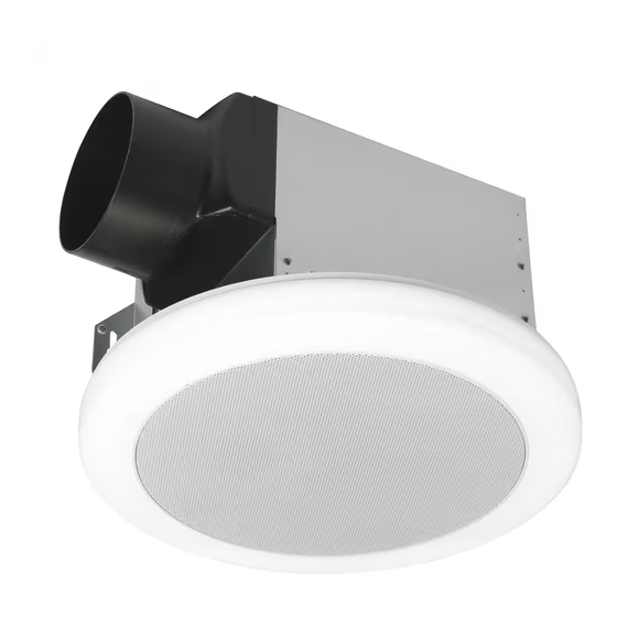
Item #1010 996 751
Model 7130-18-CE
USE AND CARE GUIDE
VENTILATION FAN WITH BLUETOOTH
SPEAKER,
®
LED LIGHT, AND NIGHT LIGHT
Questions, problems, missing parts? Before returning to the store,
call Commercial Electric Customer Service
8 a.m. - 7 p.m., EST, Monday - Friday, 9 a.m. - 6 p.m., EST, Saturday
1-877-527-0313
HOMEDEPOT.COM
The BLUETOOTH
word mark and logos are registered trademarks owned by BLUETOOTH SIG, Inc. and any use of the said mark by
®
Homewerks Worldwide is under license. Other trademark and trade names are those of their respective owners.
THANK YOU
We appreciate the trust and confidence you have placed in Commercial Electric through the purchase of this ventilation fan. We strive to
continually create quality products designed to enhance your home. Visit us online to see our full line of products available for your home
improvement needs. Thank you for choosing Commercial Electric!
READ AND SAVE THESE INSTRUCTIONS
Advertisement
Chapters
Table of Contents

Subscribe to Our Youtube Channel
Related Manuals for Commercial Electric 7130-18-CE


Summary of Contents for Commercial Electric 7130-18-CE
- Page 1 THANK YOU We appreciate the trust and confidence you have placed in Commercial Electric through the purchase of this ventilation fan. We strive to continually create quality products designed to enhance your home. Visit us online to see our full line of products available for your home improvement needs.
-
Page 2: Table Of Contents
Table of Contents Safety Information ............2 Dimensions ................6 Warranty ................3 Wiring ..................6 Product Specifications ........... 3 Typical Installation ............7 UL Compliance ............... 3 Installation - New Construction ........7 FCC Compliance ............. 4 Installation - Existing Construction ...... -
Page 3: Warranty
Warranty WHAT IS COVERED FAN – LIMITED 3-YEAR WARRANTY If the fan fails due to a defect in materials or workmanship at any time during the first THREE years of ownership, the manufacturer will replace it free of charge, postage-paid at their option. This warranty does not cover products that have been abused, altered, damaged, misused, cut or worn. -
Page 4: Fcc Compliance
FCC Compliance This device complies with part 15 of the FCC rules. Operation is subject to the following two conditions: (1) this device may not cause harmful interference, and (2) this device must accept any interference received, including interference that may cause undesired operation. This equipment has been tested and found to comply with the limits for a Class B digital device, pursuant to part 15 of the FCC Rules. -
Page 5: Tools Required
Pre-Installation (continued) TOOLS REQUIRED (NOT INCLUDED) Flathead Hammer Drill bits Duct tape screwdriver Phillips Utility knife or Electric drill screwdriver drywall saw PACKAGE CONTENTS Part Description Quantity Fan housing Grille with BLUETOOTH speaker and LED light ® HARDWARE INCLUDED Part Description Quantity Wood screw... -
Page 6: Dimensions
Pre-Installation (continued) DIMENSIONS Ceiling Ceiling Ceiling Housing Housing Housing Opening (L) Opening (W) Opening (H) Dimension (L) Dimension (W) Dimension (H) 7-3/4 in. 7-1/2 in. 7-5/16 in. 7-1/2 in. 7-1/4 in. 7 in. WIRING All wiring must be connected for full functionality. WIRING FOR 1 SWITCH OPERATION WIRING FOR 2 SWITCH OPERATION to 120 V/60 Hz... -
Page 7: Typical Installation
Typical Installation □ It is recommended to apply proper insulation around the fan to minimize heat loss and gain. Roof cap (with built-in □ This fan is designed to be installed damper) using a 4-in. duct. Using a rigid duct is Properly insulate recommended. - Page 8 Installation - New Construction (continued) Removing the duct connector □ Before mounting the fan housing (A) to the joist, remove the duct connector for easier access to the mounting hole on that side of the fan housing (A). □ Remove the duct connector by inserting a flathead screwdriver between the duct connector and the metal of the fan housing (A), and gently prying the duct connector away from the fan housing (A).
-
Page 9: Connecting The Duct
Installation - New Construction (continued) Installation - New Construction (continued) Removing the wiring box knockout □ Remove the wiring box cover from the fan housing (A) with a Phillips screwdriver (not included). □ Remove the wiring knockout from the wiring box cover with a flathead screwdriver (not included). - Page 10 Installation - New Construction (continued) Joist Attaching the housing to drywall □ Slide a holding clip (BB) through each of the two rectangular slots in the fan housing (A) on the side opposite from the ceiling joist and above the ceiling board. Ceiling board Joist Securing the mounting clips...
-
Page 11: Installing The Grille
Installation - New Construction (continued) Adjusting the color temperature of the LED light □ Move the slide switch on the back of the grille/LED light (B) to select the desired color temperature: 2700K warm white, 3000K soft white, 3500K neutral white, 4000K cool white, 5000K daylight. - Page 12 Installation - Existing Construction (continued) Removing the existing fan □ Remove the existing fan. Measuring the ceiling opening □ Measure the opening to ensure it is large enough to accommodate the 7-1/2 in. x 7-1/4 in. dimensions of the new fan housing (A). Enlarging the opening (optional) □...
- Page 13 Installation - Existing Construction (continued) Wiring the fan housing □ Pull the house wires through the hole in the wiring box cover. □ Using the quick connectors, connect the house wiring from the wall switch to the fan housing (A). 14 AWG is the Wiring box smallest conductor that should be used for branch-circuit cover...
- Page 14 Installation - Existing Construction (continued) Securing the fan housing □ Slide a holding clip (BB) through each of the four rectangular slots on opposite sides of the fan housing (A) and above the ceiling board. □ If mounting next to a joist, place the mounting clips on the two sides of the fan housing (A) perpendicular to the joist.
- Page 15 Installation - Existing Construction (continued) Joining the connectors □ Join the connectors for the BLUETOOTH speaker and LED ® light from the fan housing (A) to the grille (B). After pushing the two black connectors firmly together, twist the plastic nut to secure the connection.
-
Page 16: Connecting Your Bluetooth ® Device To The Speaker
BLUETOOTH accessory. ® 5. Choose the Commercial Electric speaker, and then enter a passkey or PIN (0000) if prompted. 6. When pairing is complete, use the BLUETOOTH speaker to play audio from your device. -
Page 17: Removing The Grille
Care and Cleaning (continued) Removing the grille □ Squeeze the mounting springs and pull the grille (B) down from the fan housing (A). □ Disconnect the connectors to remove the grille (B) from the fan housing (A). Remember to twist the ends of the black connectors to unlock them before pulling them apart. -
Page 18: Operating Instructions
Care and Cleaning (continued) Housing slots Reattaching the grille to the housing □ Attach the grille (B) by pinching the mounting springs and Mounting inserting them into the narrow rectangular slots in the fan springs housing (A). □ Turn on power source. Test the unit. Operating Instructions Using the night light □... - Page 19 Troubleshooting (continued) Problem Possible Cause Solution There is insufficient airflow intake in the room. Be sure a door or window is slightly ajar or open to allow airflow. The fan is not able to draw air out of the room without enough airflow. There is insufficient CFM.
- Page 20 Questions, problems, missing parts? Before returning to the store, call Commercial Electric Customer Service 8 a.m. - 7 p.m., EST, Monday-Friday, 9 a.m. - 6 p.m., EST, Saturday 1-877-527-0313 HOMEDEPOT.COM Retain this manual for future use. 042024...
-
Page 21: Guía De Uso Y Cuidado
GRACIAS Apreciamos la confianza que ha depositado en Commercial Electric por la compra de este ventilador. Nos esforzamos por crear continuamente productos de calidad diseñados para mejorar su hogar. Visítenos en Internet para ver nuestra línea completa de productos disponibles para sus necesidades de mejorar su hogar. -
Page 22: Información Sobre Seguridad
Índice Información sobre seguridad ........22 Dimensiones ................ 26 Garantía ................. 23 Cableado ................26 Especificaciones del producto ........23 Instalación típica ............27 Cumplimiento UL ............23 Instalación - Construcción nueva ....... 27 Cumplimiento de la normas FCC ........ 24 Instalación - Construcción existente...... -
Page 23: Garantía
Garantía QUE ESTÁ CUBIERTO VENTILADOR – GARANTÍA LIMITADA DE 3 AÑOS Si el ventilador falla debido a un defecto en el material o la mano de obra en cualquier momento durante los primeros TRES años de poseerlo, elfabricante lo reemplazará sin cargos y con el franqueo pagado a su discreción. Esta garantía no cubre productos que hayan sido objeto de abuso, alteración, daño, mal uso, corte o desgaste. -
Page 24: Cumplimiento De La Normas Fcc
Cumplimiento de la norma FCC Este dispositivo cumple con la parte 15 de las reglas de la FCC. El funcionamiento está sujeto a las dos condiciones siguientes: (1) este dispositivo no puede causar interferencias dañinas y (2) este dispositivo debe aceptar cualquier interferencia recibida, incluidas las interferencias que puedan causar un funcionamiento no deseado. -
Page 25: Herramientas Necesarias
Previo a la instalación (continuación) HERRAMIENTAS NECESARIAS (NO INCLUIDAS) Martillo Destornillador Cinta de Brocas de punta plana conducto Navaja multiusos o Destornillador Taladro sierra para Phillips eléctrico paneles de yeso CONTENIDOS DEL PAQUETE Parte Descripción Cantidad Carcasa del ventilador Rejilla con altavoz BLUETOOTH y luz LED ®... -
Page 26: Dimensiones
Previo a la instalación (continuación) DIMENSIONES Aperturo Aperturo Aperturo Dimensiones de la Dimensiones de la Dimensiones de la de techo (La) de techo (An) de techo (Al) carcasa (La) carcasa (An) carcasa (Al) 19.7 cm 19 cm 18.6 cm 19 cm 18.4 cm 17.8 cm CABLEADO... -
Page 27: Instalación Típica
Instalación típica □ Se recomienda aplicar un aislamiento adecuado alrededor del ventilador para minimizar la pérdida y ganancia de calor. Tapa de techo □ Este ventilador está diseñado para (con amortiguador instalarse con un conducto de 4 pulg. incorporado) Aísle adecuadamente Se recomienda utilizar un conducto alrededor del ventilador rígido. -
Page 28: Montaje De La Carcasa Del Ventilador
Instalación en construcción nueva (continuación) Remover el conector del conducto □ Antes de montar la carcasa del ventilador (A) en la viga, retire el conector del conducto para facilitar el acceso al orificio de montaje en ese lado de la carcasa del ventilador (A). □... - Page 29 Instalación en construcción nueva (continuación) Retiro de la tapa de la caja del cableado □ Retire la tapa de la caja de cableado de la carcasa del ventilador (A) con un destornillador de punta Phillips (no se incluyen). Tapa de □...
- Page 30 Instalación en construcción nueva (continuación) Conexión del conector del conducto Conducto de 4 pulg. □ Conecte un conducto circular de 4 pulg. (no se incluyen) al conector del conducto en la carcasa del ventilador (A), asegurándolo con cinta adhesiva o una abrazadera. □...
-
Page 31: Instalación De La Rejilla
Instalación en construcción nueva (continuación) Uniendo los conectores Una los conectores para el altavoz BLUETOOTH® y la luz □ LED de la carcasa del ventilador (A) a la rejilla (B). Después de presionar firmemente los dos conectores negros, gire la tuerca plástica para asegurar la conexión. La rejilla (B) debe estar conectada antes de encender el ventilador. -
Page 32: Instalación - Construcción Existente
Instalación en construcción existente ADVERTENCIA: RIESGO DE DESCARGA ELÉCTRICA. Asegúrese de cortar el suministro eléctrico en los cables con los que trabajará. Extraiga los fusibles o apague el cortacircuitos antes de quitar el aparato de iluminación existente o instalar uno nuevo. Retiro del ventilador existente □... -
Page 33: Conexión Del Conducto
Instalación en construcción existente (continuación) Retiro de la tapa de la caja de cableado □ Retire la tapa de la caja de cableado de la carcasa del ventilador (A) con un destornillador de punta Phillips (no Tapa de se incluyen). la caja de cableado □... - Page 34 Instalación en construcción existente (continuación) Inserción de la carcasa del ventilador □ Con el cableado y el conducto conectados, inserte la carcasa del ventilador (A) en el orificio del techo. □ Coloque la carcasa del ventilador (A) de modo que el borde inferior de la carcasa del ventilador (A) quede al ras con el tablero del techo.
- Page 35 Instalación en construcción existente (continuación) Uniendo los conectores Una los conectores para el altavoz BLUETOOTH® y la luz LED de □ la carcasa del ventilador (A) a la rejilla (B). Después de presionar firmemente los dos conectores negros, gire la tuerca plástica para asegurar la conexión.
-
Page 36: Al Altavoz
Conección de un dispositivo Bluetooth al altavoz ® 1. Para reproducir sus archivos de música personales, necesita un dispositivo inalámbrico BLUETOOTH ® 2. Configure su dispositivo a un volumen de rango medio antes de conectarlo al altavoz. 3. Sigue las instrucciones que vienen con su dispositivo BLUETOOTH para que se pueda detectar o para buscar otros accesorios BLUETOOTH ®... -
Page 37: Limpieza De La Carcasa
Cuidado y limpieza (continuación) Extracción de la rejilla □ Apriete los resortes de montaje y tire la rejilla (B) hacia abajo la carcasa del ventilador (A). □ Desconecte los conectores para quitar la rejilla (B) de la carcasa del ventilador (A). Recuerde girar los extremos de los pequeños conectores negros para desbloquearlos antes de separarlos. -
Page 38: Instrucciones De Funcionamiento
Cuidado y limpieza (continuación) Reinstalación de la rejilla a la carcasa Ranuras en la carcasa □ Coloque la rejilla (B) pellizcando los resortes de montaje y se insertan en las ranuras rectangulares estrechas en la carcasa del ventilador (A). Resortes □... - Page 39 Solución de problemas (continuación) Problema Causa posible Solución No hay suficiente flujo de aire de admisión en la Asegúrese de que una puerta o ventana esté habitación. ligeramente entreabierta o abierta para permitir el flujo de aire. El ventilador no puede extraer aire de la habitación sin suficiente flujo de aire.
- Page 40 ¿Preguntas, problemas, o piezas faltantes? Antes de devolver el producto a la tienda, llame al Servicio al Cliente de Commercial Electric de lunes a viernes de 8 a.m. a 7 p.m.,sábado de 9 a.m. a 6 p.m., hora local del Este.
Need help?
Do you have a question about the 7130-18-CE and is the answer not in the manual?
Questions and answers
The night light comes on when the **** is turned on.
The night light turns on when the switch is activated because it returns to its prior setting.
This answer is automatically generated
Is PVC ducting allowed with this product per the 2021 IRC