Advertisement
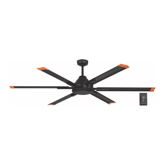
INDOOR/COVERED OUTDOOR CEILING FAN
Questions, problems, missing parts? Before returning to the store,
8 a.m. - 7 p.m., EST, Monday-Friday, 9 a.m. - 6 p.m., EST Saturday
We appreciate the trust and con dence you have placed in Commercial Electric through the purchase of this ceiling fan. We strive to
continually create quality products designed to enhance your home. Visit us online to see our full line of products available for
your home improvement needs. Thank you for choosing Commercial Electric!
USE AND CARE GUIDE
6 ft. / 8 ft. / 10 ft. HIGH VELOCITY
call Commercial Electric Customer Service
1-833-HDFANS-1 / (1-833-433-2671)
HOMEDEPOT.COM
Visual instruction of how to install this fan:
Visit www.homedepot.com and enter either the Item or Model number to nd
this fan and click the link of visual instruction in the product overview section.
6 ft.
Item #1009 847 949
1009 847 952
Model #AK366B-MBK
AK366B-TM
THANK YOU
8 ft.
Item #1009 847 950
1009 847 951
Model #AK366A-MBK
AK366A-TM
10 ft.
Item #1009 847 953
1009 847 948
Model #AK366-MBK
AK366-TM
Advertisement

Subscribe to Our Youtube Channel
Related Manuals for Commercial Electric AK366B-MBK


Summary of Contents for Commercial Electric AK366B-MBK
- Page 1 THANK YOU We appreciate the trust and con dence you have placed in Commercial Electric through the purchase of this ceiling fan. We strive to continually create quality products designed to enhance your home. Visit us online to see our full line of products available for...
-
Page 2: Table Of Contents
The following responsible party designated in FCC §2.909 is turned off at the circuit breaker or fuse box before beginning. responsible for this declaration: Model Number: AK366B-MBK, AK366B-TM, AK366A-MBK, AK366A-TM All wiring must be in accordance with the National Electrical AK366-MBK, AK366-TM Code “ANSI/NFPA 70”... -
Page 3: Warranty
Warranty The manufacturer warrants the fan motor to be free from defects in workmanship and material present at time of shipment from the factory for a period of 15 years after the date of purchase by the original purchaser. The manufacturer warrants the light kit (excluding any glass), wall control and motor controller to be free from defects in workmanship and material at the time of shipment from the factory for a period of three years after the date of purchase by the original purchaser. - Page 4 Pre-Installation (continued) HARDWARE INCLUDED NOTE: Hardware not shown to actual size. Part Description Quantity Plastic wire nut Additional blade tip Safety cable screw, lock washer and at washer Hex wrench Blade attachment screw with lock washer (additional)
- Page 5 Pre-Installation (continued) PACKAGE CONTENTS Part Description Quantity Part Description Quantity Mounting bracket (preassembled) Blade support plate (with screws and lock washers) Canopy Canopy bottom cover (preassembled) Blade Hanger ball/downrod assembly Blade arm A with RED DOT label Coupling cover Blade arm B Fan motor assembly Light cover Wall control...
-
Page 6: Installation
Installation MOUNTING OPTIONS WARNING: To reduce the risk of re, electric shock, or CAUTION: The outlet box and support structure must be personal injury, mount the fan to an outlet box marked securely mounted and capable of reliably supporting a minimum acceptable for fan support using the screws provided with the of 50 lb (22.7 kg) or less. -
Page 7: Assembly
Assembly Preparing the canopy Preparing the motor Remove the canopy bottom cover (C) from the canopy (B) by Remove the cotter pin (GG) and clevis pin (HH), and loosen turning the canopy bottom cover (C) counterclockwise. the two collar set screws (II) from the motor collar. Remove the mounting bracket (A) from the canopy (B) by Loosen two set screws (JJ) located in the hanger ball (KK) removing the non-slotted canopy mounting screw (FF) from... - Page 8 Assembly — Hanging the Fan Attaching the mounting bracket to the Hanging the fan on the mounting electrical box bracket Remove two screws (OO) from two upper sides of hanger WARNING: To reduce the risk of re, electric shock or other ball (KK).
- Page 9 Assembly — Hanging the Fan (continued) Making the electrical connections WARNING: To avoid possible electrical shock, be sure electricity is turned off at the main fuse box before wiring. NOTE: Installation of this fan requires that a three-conductor cable with ground wire be run between ceiling and wall outlet box (QQ), or the oscillating feature will not work.
- Page 10 Assembly — Hanging the Fan (continued) Installing the wall control WARNING: Hook up in "series only". Do not connect the hot and neutral wires of the electric circuit to the wall control (L) damage to the control and possible re could occur. WARNING: Remember to shut the power off at the circuit breaker or fuse box.
- Page 11 Assembly — Hanging the Fan (continued) Installing the canopy Attaching the canopy bottom cover Make sure connections are neatly tucked into the ceiling NOTE: Adjust the canopy mounting screws (FF) as necessary outlet box. until the canopy (B) and canopy bottom cover (C) are snug. Slide the canopy (B) up to the mounting bracket (A) and Attach the canopy bottom cover (C) to the canopy mounting place the key hole on the canopy (B) over the loosened...
- Page 12 Assembly — Attaching the Fan Blades Fastening the blade assemblies Attaching the blades to the blade arms to the motor NOTE: Additional blade tips (BB) in different color are included. WARNING: To reduce the risk of personal injury, do not bend Replace blade tips according to your preference before installing.
- Page 13 Assembly — Attaching the Fan Blades (continued) Fastening the blade assemblies to the motor WARNING: To reduce the risk of personal injury, do not bend the blade arms while installing, balancing the blades (H), or cleaning the fan. Do not insert foreign objects between rotating fan blades (H).
- Page 14 Assembly — Installing the Light Kit (optional-sold seperately) Attaching the LED light kit to the light kit mounting plate CAUTION: Before starting installation, disconnect the power by turning off the circuit breaker or removing the fuse at the fuse box. Turning power off using the fan switch is not suf cient to prevent electric shock.
-
Page 15: Operation
Operation WALL CONTROL OPERATING INSTRUCTIONS LEARNING PROCESS NOTE: The wall control has been pre-paired in the factory for IMPORTANT: If you have two or more fans, please follow your convenience. steps below to control each fan independently. Also follow steps below to re-pair the wall control and the receiver when needed. - Page 16 Operation (continued) WARM/COOL WEATHER OPERATING INSTRUCTIONS Speed settings for warm or cool weather depend on factors such as the room size, ceiling height, numbers of fans. NOTE: The fan reverse buttons must be pressed while the fan is running. Warm weather - (Counterclockwise Direction) A downward air ow creates a cooling effect.
-
Page 17: Care And Cleaning
Care and Cleaning Check the support connections, brackets, and blade attachments twice a year. Make sure they are secure. Because of the fan’s natural movement, some connections may become loose over time. It is not necessary to remove the fan from the ceiling. Clean your fan periodically. - Page 18 - Consult the dealer or an experienced radio/TV technician for help. Questions, problems, missing parts? Before returning to the store, call Commercial Electric Customer Service 8 a.m. – 7 p.m., EST, Monday – Friday, 9 a.m. – 6 p.m., EST, Saturday 1-833-HDFANS-1 / (1-833-433-2671) HOMEDEPOT.COM...
Need help?
Do you have a question about the AK366B-MBK and is the answer not in the manual?
Questions and answers