
Related Manuals for Asus AAEON UP Xtreme i14


Summary of Contents for Asus AAEON UP Xtreme i14
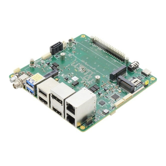
- Page 1 UP Xtreme i14 Maker Board UPX-MTL01 User’s Manual 1 Last Updated: July 2, 2024...
-
Page 2: Copyright Notice
Copyright Notice This document is copyrighted, 2024. All rights are reserved. The original manufacturer reserves the right to make improvements to the products described in this manual at any time without notice. No part of this manual may be reproduced, copied, translated, or transmitted in any form or by any means without the prior written permission of the original manufacturer. - Page 3 Acknowledgement All other products’ name or trademarks are properties of their respective owners. Microsoft®, Windows® are registered trademarks of Microsoft Corp. ⚫ Intel® and Iris® are registered trademarks of Intel Corporation ⚫ Core™ Ultra and Arc™ are trademarks of Intel Corporation ⚫...
- Page 4 Packing List Before setting up your product, please make sure the following items have been shipped: Item Quantity UP Xtreme i14 (UPX-MTL01) with Active Cooler ⚫ If any of these items are missing or damaged, please contact your distributor or sales representative immediately.
- Page 5 About this Document This User’s Manual contains all the essential information, such as detailed descriptions and explanations on the product’s hardware and software features (if any), its specifications, dimensions, jumper/connector settings/definitions, and driver installation instructions (if any), to facilitate users in setting up their product. Users may refer to the product page at AAEON.com for the latest version of this document.
- Page 6 Safety Precautions Please read the following safety instructions carefully. It is advised that you keep this manual for future references All cautions and warnings on the device should be noted. Make sure the power source matches the power rating of the device. Position the power cord so that people cannot step on it.
- Page 7 If any of the following situations arises, please the contact our service personnel: Damaged power cord or plug Liquid intrusion to the device iii. Exposure to moisture Device is not working as expected or in a manner as described in this manual The device is dropped or damaged Any obvious signs of damage displayed on the device...
- Page 8 FCC Statement This device complies with Part 15 FCC Rules. Operation is subject to the following two conditions: (1) this device may not cause harmful interference, and (2) this device must accept any interference received including interference that may cause undesired operation.
- Page 9 China RoHS Requirements (CN) 产品中有毒有害物质或元素名称及含量 AAEON Main Board/ Daughter Board/ Backplane 有毒有害物质或元素 部件名称 铅 汞 镉 六价铬 多溴联苯 多溴二苯醚 (Pb) (Hg) (Cd) (Cr(VI)) (PBB) (PBDE) 印刷电路板 ○ ○ ○ ○ 及其电子组件 外部信号 ○ ○ ○ ○ 连接器及线材 O:表示该有毒有害物质在该部件所有均质材料中的含量均在 SJ/T 11363-2006 标准规定的限量要求以下。 X:表示该有毒有害物质至少在该部件的某一均质材料中的含量超出...
- Page 10 China RoHS Requirement (EN) Poisonous or Hazardous Substances or Elements in Products AAEON Main Board/ Daughter Board/ Backplane Poisonous or Hazardous Substances or Elements Hexavalent Polybrominated Polybrominated Component Lead Mercury Cadmium Chromium Biphenyls Diphenyl Ethers (Pb) (Hg) (Cd) (Cr(VI)) (PBB) (PBDE) PCB &...
-
Page 11: Table Of Contents
Table of Contents Chapter 1 - Product Specifications..................1 Specifications ......................2 Chapter 2 – Hardware Information ..................5 Dimensions ....................... 6 Jumpers and Connectors ..................8 List of Jumpers and Connectors ................10 2.3.1 Power Button (SW1) ..................11 2.3.2 RTC (CN1) ...................... - Page 12 2.3.21 40 Pin HAT (CN31) ..................25 2.3.22 USB 2.0 Type-A/HDMI (CN32) ..............26 2.3.23 Audio Jack (CN33) ..................27 2.3.24 Fan Connector. (J1) ..................27 2.3.25 AT/ATX Mode Selection (JP1) ..............28 2.3.26 Nano SIM Card Slot (SIM1) ..............28 Chapter 3 –...
-
Page 13: Chapter 1 - Product Specifications
Chapter 1 Chapter 1 - Product Specifications... -
Page 14: Specifications
Specifications System Processor Intel® Core™ Ultra 5 Processor 125U (12M Cache, up to 4.30 GHz) Intel® Core™ Ultra 5 Processor 125H (18M Cache, up to 4.50 GHz) Intel® Core™ Ultra 7 Processor 155H (24M Cache, up to 4.80 GHz) Intel® Core™ Ultra 7 Processor 165H (24M Cache, up to 5.00 GHz) Graphics Intel®... - Page 15 System Expansion (Cont.) M.2 3052 B-Key x 1 (PCIe Gen 3 [x1], USB 3.2 Gen 2 [x1]) with Nano SIM slot (USB 3.0) SATA 6Gb/s x 1 Display Interface HDMI 2.1 x 2 DP 2.1 x 1 DP 1.4 via USB Type-C x 1 Ethernet 2.5GbE x 1 (Intel®...
- Page 16 Environment Operating Temperature With Cooler: 32°F ~ 140°F (0°C ~ 60°C), 0.5m/s airflow Operating Humidity 0% ~ 90% relative humidity, non-condensing MTBF (Hours) 1,014,016 Certification CE/FCC Class A, RoHS Compliant, REACH Chapter 1 – Product Specifications...
-
Page 17: Chapter 2 - Hardware Information
Chapter 2 – Hardware Information Chapter 2... -
Page 18: Dimensions
Dimensions Chapter 2 – Hardware Information... - Page 19 Chapter 2 – Hardware Information...
-
Page 20: Jumpers And Connectors
Jumpers and Connectors Top: Chapter 2 – Hardware Information... - Page 21 Bottom: Chapter 2 – Hardware Information...
-
Page 22: List Of Jumpers And Connectors
List of Jumpers and Connectors Please refer to the table below for all of the board’s jumpers and connectors that you can configure for your application Label Function Power Button HDMI/DP SATA SATA Power CN10 M.2 2230 E-Key Slot CN11 M.2 2280 M-Key Slot CN12 M.2 3052 B-Key Slot... -
Page 23: Power Button (Sw1)
2.3.1 Power Button (SW1) Signal Signal Power Button LED- LED+ 2.3.2 RTC (CN1) Signal Signal RTC_VCC Chapter 2 – Hardware Information... -
Page 24: Hdmi/Dp Port (Cn3)
2.3.3 HDMI/DP Port (CN3) Signal Signal Signal DP_TX0+ DP_TX0- DP_TX1+ DP_TX1- DP_TX2+ DP_TX2- DP_CLK+ DP_CLK- Pull down 1M to Pull down 1M to DP_AUX+ DP_Hot Plug DP_AUX- Detect +3.3V/1A HDMI_TX2+ HDMI_TX2- HDMI_TX1+ HDMI_TX1- HDMI_TX0+ HDMI_TX0- HDMI_CLK+ HDMI_CLK- HDMI1_CEC_O HDMI_SCL HDMI_SDA HDMI_Hot Plug +5V/0.5A Detect... -
Page 25: Sata (Cn4)
2.3.4 SATA (CN4) Signal Signal SATA_TX+ SATA_TX- SATA_RX- SATA_RX+ 2.3.5 SATA Power (CN5) Signal Signal +5V/1A Chapter 2 – Hardware Information... -
Page 26: 2230 E-Key Slot (Cn10)
2.3.6 M.2 2230 E-Key Slot (CN10) Signal Signal Signal +3.3V/2A USB2_D+ +3.3V/2A USB2_D- CNV_WR_LANE1_ CNV_WR_LANE1_ CNV_RF_RESET CNV_MODEM_CL CNV_WR_LANE0_ KREQ CNV_WR_LANE0_ CNV_UART_WAKE CNV_WR_CLK_D- CNV_BRI_RSP CNV_WR_CLK_D+ Key-E Key-E Key-E Key-E Key-E Key-E Key-E Key-E CNV_RGI_DT CNV_RGI _RSP PCIE9_TX+ CNV_BRI_DT PCIE9_TX- PCIE9_RX+ CNV_PA_BLANKIN PCIE9_RX- PCIE5_CLK_D+ PCIE5_CLK_D-... -
Page 27: 2280 M-Key Slot (Cn11)
Signal Signal Signal CNV_WT_LANE1_ CNV_WT_LANE1_ CNV_WT_LANE0_ CNV_WT_LANE0_ CNV_WT_CLK_D- +3.3V/2A CNV_WT_CLK_D+ +3.3V/2A Note: Total 2.5A for M.2 E-Key Slot. 2.3.7 M.2 2280 M-Key Slot (CN11) Signal Signal Signal +3.3V/2.5A +3.3V/2.5A PCIE4_RX3- PCIE4_RX3+ PCIE4_ TX3- +3.3V/2.5A PCIE4_TX3+ +3.3V/2.5A +3.3V/2.5A PCIE4_RX2- +3.3V/2.5A PCIE4_RX2+ PCIE4_TX2- PCIE4_TX2+ Chapter 2 –... -
Page 28: 3052 B-Key Slot (Cn12)
Signal Signal Signal PCIE4_RX1- PCIE4_RX1+ PCIE4_TX1- PCIE4_TX1+ PCIE4_RX0- PCIE4_RX0+ PCIE4_TX0- PCIE4_TX0+ Platform Reset PCIE_P3_CLK_D- PCIE_WAKE# PCIE_P3_CLK_D+ Key-M Key-M Key-M Key-M Key-M Key-M Key-M Key-M +3.3V/2.5A +3.3V/2.5A +3.3V/2.5A Note: Total 2.5A for M.2 M-Key Slot. 2.3.8 M.2 3052 B-Key Slot (CN12) Signal Signal Signal... - Page 29 Signal Signal Signal USB2_P8_D+ 3GPW_EN USB2_P8_D- Key-B Key-B Key-B Key-B Key-B Key-B Key-B Key-B USB32_1_RX- UIM_RST USB32_1_RX+ UIM_CLK UIM_DAT USB32_1_TX- UIM_PWR USB32_1_TX+ PCIE3_RX- PCIE3_RX+ PCIE3_TX- PCIE3_TX+ 5G_WWAN_PERST PCIE_CLKREQ#4 PCIE_P4_CLK_D- PCIE_WAKE# PCIE_P4_CLK_D+ CNV_PA_BLANKIN Platform Reset +3.3V/2.5A +3.3V/2.5A +3.3V/2.5A Note: Total 2.5A for M.2 B-Key Slot. Chapter 2 –...
-
Page 30: Dual Lan (Cn13)
2.3.9 Dual LAN (CN13) Signal Signal Signal LAN1_MDI0+ LAN2_MDI0+ LAN1_ACTLED- LAN1_MDI0- LAN2_MDI0- LAN1_ACTLED+ LAN1_MDI1+ LAN2_MDI1+ I219_LED_100# LAN1_MDI1- LAN2_MDI1- I219_LED_1000# LAN1_MDI2+ LAN2_MDI2+ LAN2_ACTLED- LAN1_MDI2- LAN2_MDI2- LAN2_ACTLED+ LAN1_MDI3+ LAN2_MDI3+ LAN2_LED_100# LAN1_MDI3- LAN2_MDI3- LAN2_LED_1000# R10A R10B Chapter 2 – Hardware Information... -
Page 31: Usb Type-C (Cn14)
2.3.10 USB Type-C (CN14) Signal Signal Signal Type C Port_TX0+ Type C Port_TX0- +5V/3A Type C Port_CC1 USB2_D3+ USB2_D3- Type C Port_SBU1 +5V/3A Type C Type C Port_TXRX1- Port_TXRX1+ TCP0_ TX1_D+ TCP0_ TX1_ D- +5V/3A Type C Port_CC2 USB2_D3+ USB2_D3- Type C Port_SBU2 +5V/3A Type C... -
Page 32: Uart Wafer (Cn19)
2.3.12 UART Wafer (CN19) Signal Signal RI / VCC 2.3.13 UART Wafer (CN20) Signal Signal RI / VCC Chapter 2 – Hardware Information... -
Page 33: Front Panel (Cn24)
2.3.14 Front Panel (CN24) Signal Signal RESET Power Button V3P3_S 2.3.15 DC Power Jack (CN25) Signal Signal DC_IN Chapter 2 – Hardware Information... -
Page 34: Csi Fpc Connector (Cn27)
2.3.16 CSI FPC Connector (CN27) Signal Signal Signal CSI_B1_A3_DN CSI_B1_A3_DP CSI_B0_A2_DP CSI_B0_A2_DN CSI_B_CLK_DN CSI_B_CLK_DP CSI_A0_DP CSI_A0_DN CSI_A1_DN CSI_A1_DP CSI_A_CLK_DP CSI_A_CLK_DN CSI_E0_DN CSI_E0_DP CSI_E1_DP CSI_E1_DN CSI_E_CLK_DN CSI_E_CLK_DP CSI_F1_E3_DP CSI_F1_E3_DN CSI_F0_E2_DN CSI_F0_E2_DP CSI_F_CLK_DP CSI_F_CLK_DN CSI_I2S_BCLK_MG CLKOUT1 CSI_I2S_SDO_MG CSI_I2S_FRM_MGC CSI_I2S_SDI_MGC CLKOUT0 LKOUT3 LKOUT2 CRD1_PWREN STROBE_CAM CRD2_PWREN... -
Page 35: Mipi Power (Cn34)
2.3.17 MIPI Power (CN34) Signal Signal +12V/1A 2.3.18 Dual USB 3.0 Type-A (CN28) Signal Signal Signal +5V/2A USB2_D2- USB2_D2+ USB3_RX2- USB3_RX2+ USB3_TX2- USB3_TX2+ +5V/2A USB2_D1- USB2_D1+ USB3_RX1- USB3_RX1+ USB3_TX1- USB3_TX1+ Chapter 2 – Hardware Information... -
Page 36: 2280 M-Key Slot (Cn29)
2.3.19 M.2 2280 M-Key Slot (CN29) Signal Signal Signal +3.3V/2.5A +3.3V/2.5A PCIE4_RX3- PCIE4_RX3+ PCIE4_TX3- +3.3V/2.5A PCIE4_TX3+ +3.3V/2.5A +3.3V/2.5A PCIE4_RX2- +3.3V/2.5A PCIE4_RX2+ PCIE4_TX2- PCIE4_TX2+ PCIE4_RX1- PCIE4_RX1+ PCIE4_TX1- PCIE4_TX1+ PCIE4_RX0- PCIE4_RX0+ PCIE4_TX0- PCIE4_TX0+ Platform Reset PCIE_P0_CLK_D- PCIE_WAKE# PCIE_P0_CLK_D+ Key-M Key-M Key-M Key-M Key-M Key-M Key-M... -
Page 37: Cpld And Bios Update (Cn30)
Signal Signal Signal +3.3V/2.5A +3.3V/2.5A +3.3V/2.5A Note: Total 2.5A for M.2 M-Key Slot. 2.3.20 CPLD and BIOS Update (CN30) Signal Signal Signal CPLD_TCK CPLD_TDO +1.8V CPLD_TMS SPI_CS SPI_CLK SPI_MISO CPLD_TDI SPI_MOSI SPI_HOLD 2.3.21 40 Pin HAT (CN31) Signal Signal +3.3V/2A +5V/2A I2C1_SDA +5V/2A... -
Page 38: Usb 2.0 Type-A/Hdmi (Cn32)
Signal Signal UART_RX I2S_CLK TIME_SYNC0 TIME_SYNC1 GPIO19 +3.3V/2A GPIO20 SPI_MOSI SPI_MISO GPIO21 SPI_CLK SPI_CS0 SPI_CS1 I2C0_SDA I2C0_SCL GPIO11 GPIO12 PWM0 PWM1 I2S_FRM GPIO15 I2S_RX I2S_TX Note: Total 2A(5V) and 2A(3.3V) for HAT 40 pin. 2.3.22 USB 2.0 Type-A/HDMI (CN32) Signal Signal Signal HDMI_TX2+... -
Page 39: Audio Jack (Cn33)
Signal Signal Signal HDMI_CLK+ HDMI_CLK- HDMI_SCL HDMI_SDA +5V/0.5A HDMI_Hot plug +5V/2A USB2_D- detect USB2_D+ 2.3.23 Audio Jack (CN33) Signal Signal MIC_LR_CN AUD_GND Line Out - Right Line Out - Left 2.3.24 Fan Connector. (J1) Signal Signal TACH 12V/1.5A Chapter 2 – Hardware Information... -
Page 40: At/Atx Mode Selection (Jp1)
2.3.25 AT/ATX Mode Selection (JP1) Signal Signal ATX_MODE (default) AT/ATX select AT_MODE 2.3.26 Nano SIM Card Slot (SIM1) Signal Signal UIM_PWR UIM_RST UIM_CLK UIM_GND UIM_DAT Chapter 2 – Hardware Information... -
Page 41: Chapter 3 - Software Installation
Chapter 3 Chapter 3 – Software Installation... -
Page 42: Linux Setup
Linux Setup The UP Xtreme i14 supports Linux operating systems (see Chapter 1 for specifications). For instructions on how to install a Linux OS onto your UP Xtreme i14, you can find several guides and tutorials in the wiki section of the UP website at https://up-board.org for both installing supported distributions as well as porting your own Linux build. -
Page 43: Openvino Environment For Linux
OpenVINO Environment for Linux 3.3.1 Install OS & Update Kernel Step 1: Install Ubuntu 22.04 LTS Step 2: Install 6.5 OEM Kernel to enable VPU. Command: sudo apt update sudo apt-get install linux-image-6.5.0-1009-oem Step 3: Reboot your board to apply the changes. After rebooting, check that you have booted into the correct kernel version - uname -a Output should show: linux-image-6.5.0-1009-oem... - Page 44 libegl-mesa0 libegl1-mesa libegl1-mesa-dev libgbm1 libgl1-mesa-dev libgl1-mesa-dri \ libglapi-mesa libgles2-mesa-dev libglx-mesa0 libigdgmm12 libxatracker2 mesa-va-drivers \ mesa-vdpau-drivers mesa-vulkan-drivers va-driver-all vainfo hwinfo clinfo Install linux-firmware to have GPU firmware sudo apt-get install –y linux-firmware Set user to the group (optional) usermod -a -G video user usermod -a -G render user Add GPU ID into Grub file sudo vim /etc/default/grub...
-
Page 45: Install Npu Driver
3.3.3 Install NPU Driver Enable NPU device in BIOS: CRB Setup->CRB advanced -> System Agent (SA) Configuration-> NPU Device [Enabled] Go to https://github.com/intel/linux-npu-driver/releases/tag/v1.1.0 Download and install all packages *.deb packages Verify by dmesg | grep vpu /dev/accel/accel0 as your user group (optional if you are not accessing NPU in root) chown user:user /dev/accel/accel0 Chapter 3 –... -
Page 46: Install Openvino
3.3.4 Install OpenVINO Step 1: Download OpenVINO: You must use the OpenVINO archives as they include the NPU plugin. Download the appropriate package from OpenVINO 2023.2 Linux Packages. Step 2: Proceed with OpenVINO Installation: Follow the installation instructions provided in the downloaded package to install OpenVINO on your system. -
Page 47: Install Ipu Driver (Optional)
3.3.5 Install IPU Driver (Optional) IPU driver can be found at https://github.com/intel/ipu6-drivers Chapter 3 – Software Installation... -
Page 48: Openvino Environment For Windows
OpenVINO Environment for Windows 3.4.1 OpenVINO Installation Source: https://docs.openvino.ai/2024/get-started/install-openvino.html?PACKAGE=OPENVIN O_BASE&VERSION=v_2024_2_0&OP_SYSTEM=WINDOWS&DISTRIBUTION=ARCHIVE 3.4.2 Additional Configurations for GPU and NPU Source: https://docs.openvino.ai/2024/get-started/configurations.html 3.4.3 NPU Installation Guide Operating System Support Operating System Version Details September Update (22H2) Microsoft Windows® 11 October Update (22H2) 64-bit October Update (23H2) Note: NPU will not support workloads on Windows* 10. - Page 49 How to Install/Update the NPU Driver Check if an NPU driver is already installed on your device. Right click on Windows start button and select Device Manager. Check if Intel(R) AI Boost is visible under Neural processors. If an NPU driver is installed, you need to uninstall it. In Device Manager window: Right click on the Intel(R) AI Boost and select Uninstall Device.
- Page 50 Note: If you click more than once on icon the other devices may disappear and revert to show Intel(R) AI Boost. Install the new NPU driver. Find PCI Device under Other devices. Right click it and select Update Driver. In the new Window that appears, click Browse my computer for drivers. Click on Browse button and navigate to the location where the unpacked driver was saved.
-
Page 51: Appendix A - Cables And Connectors
Appendix A Appendix A– Cables and Connectors... -
Page 52: Cables And Connectors
Cables and Connectors This table provides detailed information about the cables and connectors used by the UP Xtreme i14 (UPX-MTL01). If you have any questions about the configuration of your board, please contact your AAEON sales representative. Mating Connector Label Function AAEON P/N Vendor Model No.
Need help?
Do you have a question about the AAEON UP Xtreme i14 and is the answer not in the manual?
Questions and answers