Meinberg microSync HR100/DC Technical Reference
Hide thumbs
Also See for microSync HR100/DC:
- Technical reference (52 pages) ,
- Technical reference (89 pages)

Related Manuals for Meinberg microSync HR100/DC


Summary of Contents for Meinberg microSync HR100/DC
- Page 1 TECHNICAL REFERENCE microSync HR100/DC 29th July 2021 Meinberg Funkuhren GmbH & Co. KG...
-
Page 3: Table Of Contents
4.10 Return of Electrical and Electronic Equipment ......5 microSync HR100/DC Connectors GNSS Antenna . - Page 4 10.4 Technical Specifications - MBG S-PRO surge protection ..... . . 10.4.1 MBG S-PRO - Physical Dimensions ....... 10.4.2 Installation and Grounding .
-
Page 5: Imprint
1 Imprint 1 Imprint Meinberg Funkuhren GmbH & Co. KG Lange Wand 9, 31812 Bad Pyrmont / Germany Phone: + 49 (0) 52 81 / 93 09 - 0 Fax: + 49 (0) 52 81 / 93 09 - 230 Internet: https://www.meinbergglobal.com... -
Page 6: Microsync Introduction
• High performance (S)NTP server • Half rack solution for a space efficient design • Different Oscillator options for advanced holdover performance • Meinberg Device Manager for configuration and status monitoring • Three-year manufacturer‘s warranty • Unlimited technical support including firmware updates... -
Page 7: Technical Specifications Microsync Chassis
3 Technical Specifications microSync Chassis 3 Technical Specifications microSync Chassis Protection Rating: IP30 Operating Temperature: –20 to 55 C (–4 to 131 F) As tested per IEC 60068-2-1, Cold: –40 C (–40 F) As tested per IEC 60068-2-2, Dry Heat: 85 C (185 F) Storage Temperature: –30 to 70 C (–22 to 158 F) Relative Humidity:... -
Page 8: Important Safety Information
Meinberg Funkuhren shall not be responsible for any damage arising due to non-observance of these regulations. -
Page 9: Used Symbols
4 Important Safety Information 4.2 Used Symbols The following symbols and pictograms are used in this manual. To illustrate the source of danger, pictograms are used, which can occur in all hazard classes. Symbol Beschreibung / Description IEC 60417-5031 Gleichstrom / Direct current IEC 60417-5032 Wechselstrom / Alternating current IEC 60417-5017... - Page 10 The product manuals are stored on a USB stick, which is delivered with the system. The manuals can also be downloaded from the Meinberg website https://www.meinbergglobal.com. Enter the respective system name into the search box at the top of the page.
-
Page 11: Security During Installation
4 Important Safety Information 4.3 Security during Installation WARNING! Preparing for Commissioning This built-in unit, has been designed and examined according to the requirements of the standard IEC 62368-1 "Audio/video, information and communication technology equipment - Part 1: Safety requirements". When the built-in unit is used in a terminal (e.g., housing cabinet), additional requirements according to Standard IEC 62368-1 must be observed and complied with. - Page 12 Connecting Data Cables During a thunderstorm, data transmission lines must not be connected or disconnected (risk of lightning). When wiring the devices, the cables must be connected or disconnected in the order of the arrangement described in the user documentation accompanying the device. Always attach all cables to the plug during connection and removal.
-
Page 13: Protective Conductor- / Ground-Terminal
4 Important Safety Information 4.4 Protective Conductor- / Ground-Terminal ATTENTION! In order to ensure safe operation and to meet the requirements of IEC 62368-1, the device must be correctly connected to the protective earth conductor via the protective earth connection terminal. If an external earth connection is provided on the housing, it must be connected to the equipotential bonding rail (grounding rail). -
Page 14: Safety During Maintenance
4.6 Safety during Maintenance WARNING! When you are expanding the device, use only device parts that are approved for the system. Non-observance may result in injury to the EMC or safety standards and cause malfunction of the device. If device parts, which are released for the system, are extended or removed there may be a risk of injury in the area of the hands, due to the pull-out forces (approx. -
Page 15: Cleaning And Care
4 Important Safety Information 4.8 Cleaning and Care ATTENTION! Do not wet clean the appliance! Penetrating water can cause considerable dangers to the user (e.g., electric shock). Liquid can destroy the electronics of the device! Liquid penetrates into the housing of the device and can cause a short circuit of the electronics. -
Page 16: Return Of Electrical And Electronic Equipment
Return and Collection Systems For returning your old equipment, please use the country-specific return and collection systems available to you or contact Meinberg. The withdrawal may be refused in the case of waste equipment which presents a risk to human health or safety due to contamination during use. -
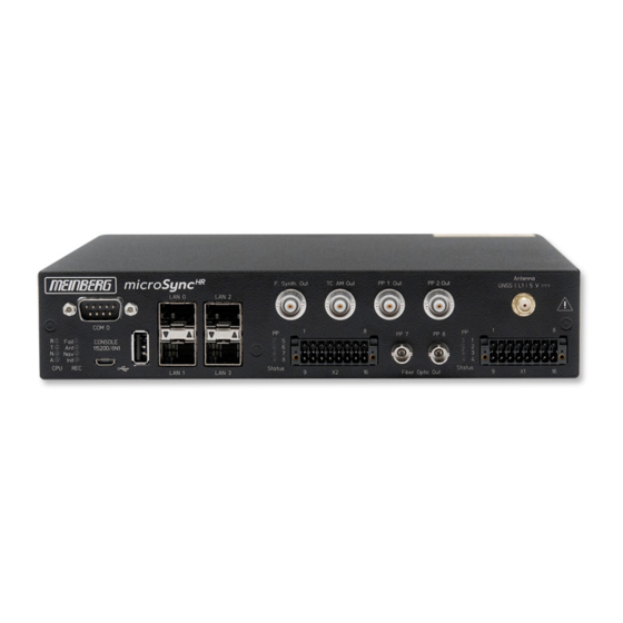
Page 17: Microsync Hr100/Dc Connectors
5 microSync HR100/DC Connectors 5 microSync HR100/DC Connectors 5.1 GNSS Antenna Antenna type Multi GNSS L1 antenna with integrated lightning protection Receiver type 72-channel GPS/Galileo/Glonass/ Beidou Frequency band L1 / E1 / B1 , 1575.42 +- 10 MHz / 1602-1615 MHz... -
Page 18: Programmable Pulse Output
5.2 Programmable pulse output Signal output Programmable pulses Signal level: TTL; 2.5 V into 50 Ohm Connector: BNC, female Cable: Coaxial cable, shielded Pulse outputs: Pulse Per Second Cyclic Pulse Single Shot Timer Idle All Sync Time Sync Position OK DCF77 Marks Pulse Per Hour Pulse Per Min... -
Page 19: Frequency Synthesizer Output
5 microSync HR100/DC Connectors 5.4 Frequency Synthesizer Output Output signal unbalanced sinusoidal signal Frequency output: 0,1 Hz - 10 MHz F. Synth Out Signal Level: into 50 Connection type: BNC, female Cable: shielded coax line 5.5 RS-232 COMx Timestring Data transfer:... -
Page 20: Status Indicators - Cpu And Receiver
5.6 Status Indicators - CPU and Receiver CPU: —————————————————————————– R (Receiver) green: The reference clock (e.g. build-in GNS) provides a valid time red: the reference clock does not provide a valid time T (Time Service) green: NTP is synchronized to the reference clock, e.g. -
Page 21: Usb Interface
5 microSync HR100/DC Connectors 5.7 USB Interface Signal Signal Type Connector —————————————————————————– USB Terminal USB-to- Micro-USB Type B serial console USB Host USB connector USB Type A management CPU 5.8 LAN Network Interfaces Gigabit Ethernet (GbE), 100/1000 MBit - SFP... -
Page 22: Dmc X2 Terminal Connector
5.9 DMC X2 Terminal Connector Note: The connector on the device side and the connection socket of the X2 terminal are provided with coding pins to avoid confusion with the X1 connection terminal. Pin 1 PP 5+ programmable pulse (optocoupler) Pin 2 PP 5 programmable pulse (RS-422A) -
Page 23: Fiber Optic - Programmable Pulse Output
5 microSync HR100/DC Connectors 5.10 Fiber Optic - Programmable pulse Output Output signal: Programmable pulses, fiber optic Wave lenght: 850 nm (multi mode) Connection type: ST-connector GI 50/125 m or 62.5/125 m gradient fibre Pulse outputs: Pulse Per Second Cyclic Pulse... -
Page 24: Dmc X1 Terminal Connector / Dc Power Supply
5.11 DMC X1 Terminal Connector / DC Power Supply Note: The connector on the device side and the connection socket of the X1 terminal are provided with coding pins to avoid confusion with the X2 connection terminal. Connection Type: DMC Connector Power Supply: Pin 1: -DC In... - Page 25 5 microSync HR100/DC Connectors Scheme Terminal assignment Programmable Pulses Standard (Opto Coupler) Four programmable outputs (PP 1 - PP 4) DC-insulated by optocouplers PP 1 + Channel 1 PP 1 = 55 V CEmax PP 2 + = 50 mA...
-
Page 26: Gnss Satellite Navigation
6 GNSS Satellite Navigation The satellite receiver clock GNS has been designed to provide extremely precise time to its user. The clock has been developed for applications where conventional radio controlled clocks can´t meet the growing requirements in precision. High precision available 24 hours a day around the whole world is the main feature of the new system which receives its information from the satellites of the russian GLONASS (GLObal NAvigation Satellite System) and the american GPS (Global Positioning System). -
Page 27: Time Zone And Daylight Saving
6 GNSS Satellite Navigation 6.1 Time Zone and Daylight Saving GPS system time differs from the universal time scale (UTC) by the number of leap seconds which have been inserted into the UTC time scale since GPS was initiated in 1980. The current number of leap seconds is part of the navigation message supplied by the satellites, so the internal real time of the GNS is based on UTC time scale. -
Page 28: Installation Gnss Antennas
7 Installation GNSS Antennas For our combined GPS/GLONASS/Galileo/BeiDou satellite receivers, there are two available antennas, which are designed for different tasks or applications. Standard accessories include the active Multi GNSS L1 antenna, which can receive signals from GPS, GLONASS, Galileo and Beidou satellite systems. This antenna is ideally for stationary systems, operates with a 5V DC supply voltage provided by the receiver and has an integrated surge protection. - Page 29 7 Installation GNSS Antennas Antenna Mounting Mount the antenna at a minimum distance of 50 cm Free view to the sky! from other antennas to a vertical pole with an outer diameter from 60 mm to 215 mm (2 inch) with the mounting kit included in the scope of delivery.
- Page 30 Earth cable to PE rail To ground the antenna cable, connect the surge Cable circa 1,5 mm Ø protection with a grounding cable to a equipotential attached to the surge protection bonding rail (see figure). After installation, connect the other end of the as short as possible antenna cable to the socket of the surge protection.
- Page 31 7 Installation GNSS Antennas Antenna splitter option Several receivers can be connected to one antenna via the antenna splitter. Make sure, that the total length of a route going from the antenna via the splitter to the receiver, does not exceed the maximum cable length. The splitter can be installed at any position between antenna or, if used, the surge protector and receiver.
-
Page 32: Installation Of The Rv-76G Gps/Glonass Antenna For Mobile Applications
7.2 Installation of the RV-76G GPS/GLONASS Antenna for mobile Applications Mounting the antenna Source: Datasheet gps-glonass_antenna_rv-76g_catalog_v1.pdf (Sanav) Date: 29th July 2021 microSync... -
Page 33: Starting Of Operation
The software is delivered on the USB stick included in the scope of delivery and does not need to be in- stalled or copied on the PC. The Meinberg Device Manager can be started directly from the USB data carrier. -
Page 34: Initial Network Configuration
To configure a microSync system you need the Meinberg Device Manager software. This tool is provided on the supplied USB stick. You can always download the latest version from our website: https://www.meinbergglobal.com/english/sw/mbg-devman.htm... -
Page 35: Network Configuration With The Mbgoswizard
After the successful connection via the serial console (as described in chapter Initial Network Configura- tion), you can now use the Meinberg OS Wizard to configure the IP address for the first time. Select the same subnet mask as for your network adapter and an IP address which is located in the same subnet. -
Page 36: Initial Start Of Operation
8.2 Initial Start of Operation First install the Meinberg Device Manager software supplied on the USB stick. After the setup, start the program. If you do not want to perform a setup on your computer, you can start the portable version of the Meinberg Device Manager software directly on the USB stick: USB Drive/Software/MbgDevMan/mbgdev- man_portable/mbgdevman.exe. - Page 37 User and Password fields are already filled out. Silent Login You have the option that the Meinberg Device Man- ager does not ask for a user name and password every time you log in. Custom Alias Assign a custom alias for better identification of indi-...
-
Page 38: Technical Appendix
Framing: 7E1, 7E2, 7N2, 7O1, 7O2, 8E1, 8N1, 8N2, 8O1 Default Setting: COM 0: 19200, 8N1 Meinberg Standard time string, per second Time Code Outputs: Unbalanced modulated sine wave signal: (MARK), 1 V (SPACE) into 50 PWM DCLS-signal: TTL into 50... - Page 39 9 Technical Appendix GNS Receiver (GNS181) Type of receiver: GPS/GLONASS/Galileo/BeiDou receiver Number of channels: 72 Frequency band: GNSS L1 GPS: 1575.42 10 MHz GLONASS: 1602-1615 MHz Galileo: 1542.5 MHz BeiDou: 1561.09 MHz Antenna: Combined GPS/GLONASS antenna 3 dB Bandwidth: 1590 30 MHz Impedance: Gain:...
-
Page 40: Configuration Options
9.2 Configuration Options Receiver Options RECEIVER TYPE SIGNAL TYPE VALUE CONNECTOR Meinberg GPS IF, 12-channel IF (Meinberg Antenna)) 15 V DC Meinberg GNS-UC GPS/Galileo IF IF (Meinberg Antenna)) 15 V DC GNSS (GPS, GLONASS, Galileo, BeiDou), 72-channel L1/E1/B1 band 5 V DC... -
Page 41: Technical Appendix - Gnss Antennas + Accessories
10 Technical Appendix - GNSS Antennas + Accessories 10 Technical Appendix - GNSS Antennas + Accessories 10.1 Information about the 40dB Multi GNSS Antenna GPS L1 / GLONASS L1 / GALILEO E1 / BeiDou B1 Frequency Band The GPS, GLONASS, Galileo and BeiDou satellites are not stationary but circle round the globe in a period of about 12 hours. -
Page 42: Antenna Cable
10.2 Antenna Cable: Cable type Cable (mm/in) Attenuation at 100 MHz max. Cable lenght (m/ft) used for receiver type (db)/100m/328ft RG58/CU 5/0.2 300/984 GPS/GNS-UC/PZF RG213 10,3/0.41 700/2297 GPS/GNS-UC H155 5,4/0,21 70/230 GNM/GNS H2010 Ultraflex 7,3/0,29 150/492 GNM/GNS Further values can be found in the data sheet of the cable used. 10.3 Antenna Short-Circuit (Only for assembly groups with front display) In case of an antenna line short-circuit the following message appears in the display:... -
Page 43: Technical Specifications - Mbg S-Pro Surge Protection
10 Technical Appendix - GNSS Antennas + Accessories 10.4 Technical Specifications - MBG S-PRO surge protection Attachment plug with replaceable gas discharge tube for coaxial signal interfaces. Connection: N connector female/female. The MBG S-PRO set includes a surge voltage protector (Phoenix CN-UB-280DC-BB), a pre-assembled coax cable and a mounting bracket. - Page 44 Max. discharge current (8/20) s maximum (Core-Shield) 20 kA Nominal pulse current (10/1000) s (Core-Shield) 100 A Impulse discharge current (10/350) s, peak value I 2,5 kA Output voltage limitation at 1 kV/ s (Core-Earth) spike 900 V at 1 kV/ s (Core-Earth) spike 900 V Response time tA (Core-Earth)
-
Page 45: Mbg S-Pro - Physical Dimensions
10 Technical Appendix - GNSS Antennas + Accessories 10.4.1 MBG S-PRO - Physical Dimensions 15,8 10.4.2 Installation and Grounding microSync Date: 29th July 2021... -
Page 46: Information About The Rv-76G Gps/Glonass Antenna For Mobile Applications
10.5 Information about the RV-76G GPS/GLONASS Antenna for mobile applications General Information The RV-76G GPS/GLONASS antenna is the integration of a high performance GPS patch antenna and a state-of-the-art low noise amplifier into a very low-profile, extremely compact and fully waterproof enclosure which, when connected to a GPS receiver with 5 V DC antenna power, provide adequate signal amplification and out-band rejection. - Page 47 10 Technical Appendix - GNSS Antennas + Accessories Overall performance (antenna element, LNA & cable) Center frequency 1575.42 MHz 10 MHz & 1602 MHz 8 MHz Gain at 90 27 + 3dB (cable loss) Note: mounted on the 70 mm x 70 mm square ground plane Environmental Conditions Operating temperature ~40 C +85 C...
-
Page 48: Rohs And Weee
Any transportation expenses for return- ing this product (at its end of life) have to be incurred by the end user, whereas Meinberg will bear the costs for the waste disposal itself. Date: 29th July 2021... -
Page 49: Declaration Of Conformity
12 Declaration of Conformity Declaration of Conformity Doc ID: microSync HR100/DC-2021-02-23 Hersteller Meinberg Funkuhren GmbH & Co. KG Manufacturer Lange Wand 9, D-31812 Bad Pyrmont erklärt in alleiniger Verantwortung, dass das Produkt, declares under its sole responsibility, that the product...
Need help?
Do you have a question about the microSync HR100/DC and is the answer not in the manual?
Questions and answers