Table of Contents
Advertisement
Quick Links
Advertisement
Table of Contents

Subscribe to Our Youtube Channel
Related Manuals for KRUG+PRIESTER EBA 4815


Summary of Contents for KRUG+PRIESTER EBA 4815
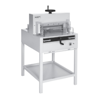
- Page 1 Guillotines Operating Instructions EBA 4815 EBA 4850 www.eba.de...
-
Page 2: Table Of Contents
Table of Contents Safety precautions Intended use Installation Startup Operation / Operating elements Blade and cutting stick replacement Maintenance and cleaning Annual inspection / Safety test Possible malfunctions Accessories Technical data EC-declaration of conformity - 2 -... -
Page 3: Safety Precautions
Safety precautions Please read these operating instructions before putting the machine into operation and observe the safety precautions. The operating instructions must always be available. Children must not operate the machine! Do not reach beneath the blade! Never leave the blade unattended! Do not extract or transport the blade without protection! (See page 25 and 27). -
Page 4: Intended Use
Safety precautions / Intended use Do not use any spray cans with flammable content near to the cutting machine! Do not use any flammable cleaning agents. Intended use The machine is designed for cutting stacks of paper to a specified size. This machine is constructed for "one-man operation"... - Page 5 Safety precautions Disconnect from the mains before starting any service work or before removing the panels! Replacement of blade and cutting stick may be performed only when the main switch is switched off! - 5 -...
- Page 6 Safety precautions All components which could endanger the operator are covered by a guard! Operating the machine without safety device is forbidden! (Front safety guard (A), rear screwed safety guard (B) and panel (C). - 6 -...
- Page 7 Safety precautions The dangerous cutting movement is safeguarded by a movable guard (A) and a safety two-handed control system! (B) Before working with the machine and after every blade replacement the automatic cut-off function of safety guard (A),(correct if distance between cover and table is <...
- Page 8 Safety precautions Protect mains cable against heat, oil and sharp edges! Connect the power cord to a single phase socket. 230V / 10A min 115V / 15A min Ensure free access to mains! - 8 -...
- Page 9 Safety precautions When not in use for a longer period switch off. (Main switch to "0"). Danger! Blade must always be covered by the pressing bar. Clamping Blade - 9 -...
-
Page 10: Installation
Installation Remove the stand from the wooden pallet. 4 strong people are required to lift the machine from the pallet and place it on the stand. Secure with 4 screws (A). Put the shelf (B) on the stand. (Parts and tools are in the tool set (C). - Page 11 Installation Tools can be kept in the holder provided. Cutting sticks (A) can be put in the tool holder - 11 -...
- Page 12 Installation Tighten the backgauge crank (A). Parts and tools are in the tool set (C). Only 4815 Attach the enclosed hand-wheel for clamping. Parts ans tools are in the tool set (C). - 12 -...
-
Page 13: Startup
Installation / Startup Side tables (A), left and right are available as an option (No. 9000 528). Startup Plug into socket. The machine must be connected directly to the socket. - 13 -... - Page 14 Startup It is forbidden to operate the machine if the operating and safety instructions have not been understood. Please check the safety devices are functioning and complete before use. • All covers have to be mounted (A). • The release for cutting is allowed only if the cover is closed and the two-hand safety device is operated at the same time (B) •...
-
Page 15: Operation / Operating Elements
Operation / Operating elements Operating elements - Safety two-handed control system Pre-clamping (only 4850) and cutting - Overload switch Blade drive 4815 Blade drive, clamp drive, 4850 - Display cutting size (cm or inch) - Main switch - Crank handle for backgauge setting - Key switch - Paper clamp (only 4815) - Page 16 Operation Position the main switch to "I" (A). Insert the for the control system and move it to the right (B). Open the safety guard (C). The machine is now ready for use. - 16 -...
- Page 17 Operation The measurement is set with the backgauge crank.(A) The symbol – rotary direction – moves to the right on the display (B) (see picture C). The rotary direction of the backgauge crank (A) is indicated on the right. Keep turning the backgauge crank to the right until a measurement appears (see picture E).
- Page 18 Operation Cut according to markings Optical cutting line (A) that indicates the exact position of the cut. Blade cuts on the front edge (B) of the light beam. (Only use when no exact cut is required). • Adjust the backgauge with the crank handle to the back.
- Page 19 Operation Position the paper on the backgauge (A) and side lays left or right (B). To move paper stacks, please use the paper knock-up block (C) provided. (Run backgauge to the front for turning the paper stack). Only 4815 Clamping is released by the hand-wheel. Before every cut lower the clamp by turning the hand-wheel to the right and tighten with a light twist.
- Page 20 Operation 4850 The clamp moves automatically when cutting is activated. The paper can also be pressed in advance. Clamping and cutting is activated by pressing actuators (A) on the front table. 4850 The actuator has 2 switching steps: 1. pre-clamping 2.
- Page 21 Operation Close the safety guard. Cutting activation: Press both buttons of the two-handed control system activation (A) simultaneously and them pressed until the paper is completely cut. To interrupt or stop cutting: To interrupt or stop cutting, release both buttons (A) of the two-hand control. - 21 -...
-
Page 22: Blade And Cutting Stick Replacement
Blade and cutting stick replacement If the cutting quality decreases: • Check the cutting depth (see page 30). • Check the cutting stick (see page 26). • Replace or grind the blade (see page 22 - 30). The blade cannot be ground if the blade height is less than 83 mm/3,29 inches. - Page 23 Blade and cutting stick replacement Turn the blade depth adjustment screw to the left until it stops. (Screwdriver found in tool set) (A). Close the safety guard (1.). Lower the blade by pressing both cutting actuators (2.). Keep one actuator pressed and turn off the main switch (3.).
- Page 24 Blade and cutting stick replacement The 3 eccentrics are now exposed and should be turned counter clockwise to position "0" with the special wrench and attachable extension pipe (A) (in the tool set). The slot must correspond to position "0" (B). Unscrew the blade screws (C) on the right hand side.
- Page 25 Blade and cutting stick replacement Position the main switch to "0" (1.) Remove the 2 blade screws on the elongated holes (2.). Then put the blade changing tool (A) into place and fasten it to the blade (3.). Remove 2 blade screws (1.). Loosen the grips (2.) of the blade changing tool (A) lightly and allow the blade to be taken downwards out of the machine (3.).
- Page 26 Blade and cutting stick replacement Take out the cutting stick with a small screw- driver. If needed the cutting stick can be turned or exchanged. (The cutting stick can be used eight times). Replacing the cutting stick (not the blade). •...
- Page 27 Blade and cutting stick replacement Take the exchange blade carefully out of the blade box and screw it to the blade changing tool (A). • Make sure there is a space ot 11 mm or 0.43 inches! (B). • Blade must be covered! (C). Danger! Risk of injury! 11 mm 0.43 inch...
- Page 28 Blade and cutting stick replacement Lightly tighten 2 of the 5 blade screws (1.). Remove the blade changing tool (2.). Lightly tighten the remaining blade screws (3.). Lightly screw in the right blade screw (A) when the blade is lowered. Remove all tools and distribute paper along the entire cutting length (1.).
- Page 29 Blade and cutting stick replacement Close the safety guard (1.) Lower the blade by pressing both cutting buttons (2.). Keep one button pressed and turn off the main switch (3.). 2. 2. Open the safety guard (4.). With the special wrench (B) the 3 eccentrics should be screwed down (5.) until the paper is cut along the entire length of the blade (The...
- Page 30 Blade and cutting stick replacement Paper cutting test. If the last sheet or several sheets are not completely cut, gradually turn the knob for blade depth adjustment (A) ¼ turn to the right until the paper is cut along the entire length. Do not set too low as blade will become blunt sooner.
-
Page 31: Maintenance And Cleaning
Maintenance and cleaning Maintenance work may only be performed by trained staff. Danger! Disconnect the mains before starting any service work or before removing the cover. Grease the backgauge (A) control weekly with a grease gun. Advance the backgauge as far as possible to the front (use special grease for cutting machines). -
Page 32: Annual Inspection / Safety Test
Maintenance and cleaning Annual inspection Next Maintenance To maintain the operational safety and to prevent premature wear, we recommend an annual inspection and maintenance of the machine by a qualified service technician. Krug & Priester GmbH & Co. KG 72336 Balingen - Germany Parts &... -
Page 33: Possible Malfunctions
Possible malfunctions Machine does not function! Is the machine plugged in? Main switch to position "I"? (A) Control system activated? (B) (Turn key to the right) Check the units fuse and the on-site circuit breaker! Release a cut see page 19 and 20. - 33 -... - Page 34 Possible malfunctions Cut cannot be made. • If cover is open: close it. • If cover is closed: open and re-close it. (Security check). - 34 -...
- Page 35 Possible malfunctions Machine turns off: • Machine overloaded. Safety button (A) ejects. (Allow 1 minute cooling time and reset the safety button (A). • Machine blocked. • Blade is blunt. Eliminate the cause, and push the safety button (A). Only 4850 •...
- Page 36 Possible malfunctions Does not cut through the last sheet: • Turn or turn around the cutting stick (A), readjust the blade by means of the blade adjusting knob (B) (see page 30). Poor cutting quality or blade stays in the paper stack.
- Page 37 Possible malfunctions Motor runs but blade does not move downwards. • Security brake has been activated! Inform the Service Team! • www.krug-priester.com "Service" service@krug-priester.com Service Display illumination off • Machine is plugged in? (A) • Main switch on position "I"? (B) •...
- Page 38 Possible malfunctions Did none of the specified solutions help you with your problem? Contact: Service • www.krug-priester.com • service@krug-priester.com Service - 38 -...
-
Page 39: Accessories
Accessories Recommended accessories: Blade • No. 9000 021 4855 HSS - Blade • No. 9000 126 4855 Cutting stick (6 pieces) • No. 9000 022 4855 Blade changing tool • No. 9000 523 4855 Grease tube • No. 9000 625 Grease cartridge •... -
Page 40: Technical Data
Technical data Technical data: • Power supply: 230V/50Hz/1~,120V/60Hz/1~ • Cutting height: 80 mm • Sound level EN 13023: < 70 dB (A) • Leakage current < 3,5mA • Power cord gauge min. 1,5mm (230V). • Power cord gauge AWG 14 (15A) (120V) (4815) •... - Page 41 Technical data This machine is approved by independent safety laboratories and is in compliance with the EC-regulations 2006/42/EG and 2014/30/EU. Sound level information: The sound level is < 70 db (A) as defined by EN 13023. Subject to alteration without notice. - 41 -...
- Page 42 Technical data The company Krug + Priester has the following certifications: • Quality management system according to DIN EN ISO 9001:2015 • Environmental management system according to DIN EN ISO 14001:2015 • Energy management system according to DIN EN ISO 50001:2018 - 42 -...
-
Page 43: Ec-Declaration Of Conformity
EC-declaration of conformity EC-declaration of conformity - Herewith we declare that GS-ID No. UL-ID No. 4815 11481501 10481001 4850 11485001 10485001 - complies with the following provisons applying to it 2006/42/EG: EC Machinery directive 2014/30/EG: EMV Electromagnetic compatibility directive 2011/65/EU, 2015/863/EU RoHS directive - Applied harmonised standards in particular EN 60204-1;... - Page 44 EBA • Made in Germany • Document Shredders • • Trimmers and Guillotines • Krug & Priester GmbH & Co. KG Simon-Schweitzer-Str. 34 D-72336 Balingen (Germany) www.krug-priester.com 02-2022 18.11.2022 zm 9700205 9700148...
Need help?
Do you have a question about the EBA 4815 and is the answer not in the manual?
Questions and answers