
Subscribe to Our Youtube Channel
Related Manuals for KRUG+PRIESTER IDEAL THE 56


Summary of Contents for KRUG+PRIESTER IDEAL THE 56
- Page 1 EN Operating Instructions THE 56 IDEAL EBA THE 56 EN 9700319 9700330 09-2022 20231127zm...
-
Page 2: Table Of Contents
Table of Contents Safety Precautions Intended Use Overview and Parts Designation Scope of Delivery / Options Setting Up Commissioning Operating Operating / Multi-Touch Display Blade Change Changing the Cutting Stick Maintenance and Upkeep Yearly Maintenance / Safety Inspection Multi-Touch Display Settings Possible Malfunctions Multi-Touch Display Possible Malfunctions Cutting Machine Accessories / Options... -
Page 3: Safety Precautions
Safety precautions Please read these operating instructions before putting the machine into operation and observe the safety precautions. The operating instructions must always be available. Children must not operate the machine! Do not reach beneath the blade! Never leave the blade unattended! Do not extract or transport the blade without protection! (See page 27). - Page 4 Safety Precautions Safety precautions - Multi-touch display • The multi-touch display is firmly fitted to the machine. • Never expose this multi-touch display to rain or moisture to prevent any fire or electric shock risk. Dangerous high voltages are present inside the multi-touch display.
- Page 5 Safety Precautions Protect the power cable from heat, oil and sharp edges! The machines are default-delivered with the following setting: • Voltage 230 V (120 V) 1 ph. • Frequency 50 Hz (60Hz). Disconnect the mains plug prior to servicing and when removing any panels.
-
Page 6: Intended Use
Safety Precautions / Intended Use Safety Precautions Shut down if not in use for a long period. (Main switch to “0”). Intended use This machine is for cutting stacks of paper to a certain size. This machine is only for a “One-man operation”! Caution! Any staples and the like damage the cutting blade. -
Page 7: Overview And Parts Designation
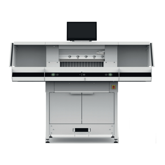
Overview and Parts Designation Paint brush (in the tool kit as delivered) Blade Back gauge Cutting stick Test rod for the safety light beam curtain (in the tool kit as delivered) Front table Two-hand cutting activation (operating buttons) Operating control for electrical back gauge adjustment Main switch (lockable) Tool panel (tool kit) -
Page 8: Scope Of Delivery / Options
Scope of Delivery / Options Scope of delivery Cutting machine Multi-touch display Paper knock-up block Tool panel: • Blade changing device • Clamp bar cover • Tool kit • Operating instructions Options Set of side tables Order No. 9000 552 (The add-on instructions are enclosed with the side tables.) Base frame panelling... -
Page 9: Setting Up
Setting Up The adjustable feet are used to level the machine and effect height adjustments: • Level machine with spirit level, 4x adjustable feet AF17. • Reference face machine table Caution! Disconnect mains plug before assembling the display. • Insert display into the slots as far down as possible. -
Page 10: Commissioning
Commissioning Plug in power cable at the power socket. Main switch at Position “I” . The reference point for the back gauge is automatically moved to. The machine is operational. Caution! Avoid any rapid machine switching on and off. Wait for at least 30 seconds until the control unit has fully run down. -
Page 11: Operating
Operating The dimension is set manually by way of the operating control for the electrical back gauge adjustment or by way of programming the cutting size at the multi-touch display Cutting line indicator - optical: Cut shown by optical red light beam , blade cut at the front edge of the light beam. - Page 12 Operating Clamp bar cover: To prevent clamp bar pressure marks on sensitive materials, a clamp bar cover provided (tool panel). Dismantling: • Remove clamp bar cover downwards by hand or gently press into the recess using the provided spanner ( in the tool kit). ...
-
Page 13: Operating / Multi-Touch Display
Operating / Multi-Touch Display home - mode Starting machine • Main switch at Position “I”, the reference point for the back gauge is automatically moved to (operating buttons light up yellow). After a complete start 56.00 cm is shown on the display, the operating buttons light up green. - Page 14 Operating / Multi-Touch Display home - mode Cutting to a specified dimension • Enter dimension in the numeric keypad. Dimension appears in red (an incorrectly entered dimension can be cleared by tapping START • - tap on. Dimension is moved to and again appears in white after reaching the required position.
- Page 15 Operating / Multi-Touch Display home - mode Consecutive dimensioning function • Enter start dimension in the numeric keypad. START • Start entered dimension with • Slide paper to back gauge • Tap on the consecutive dimensioning symbol • Enter consecutive dimension and save with •...
- Page 16 Operating / Multi-Touch Display home - mode PROGRAM MODE Clamp bar cover (status indication) • An installed clamp bar cover is shown by the symbol in the numeric keypad. Pressing (Status display) • The symbol is shown during the full pressing operation.
- Page 17 Operating / Multi-Touch Display PROGRAM MODE Incorporating program step With symbol a fresh step can, for instance, be incorporated ahead of selected Step 2 or directly behind using the symbol. Editing program step Following inputs are possible in a program step: Consecutive cut •...
- Page 18 Operating / Multi-Touch Display PROGRAM MODE Saving program step • Accept program step with when all the required features are set. Program step is shown with the inputted features. Call up next step Select program step • Program step by going upwards / downwards Select swipe and directly tap on.
- Page 19 Operating / Multi-Touch Display FILE MANAGER Processing, interrupting and stopping program • Tap on the symbol to run down a program without cutting. Individual steps can also be selected by swiping upwards / downwards and directly started by tapping the symbol.
- Page 20 Operating / Multi-Touch Display SETTINGS Searching in the FILE MANAGER • The search function is limited to the word search in the FILE MANAGER mode. In general This item is for general basic settings of the machine / multi-touch display In general Date / time •...
- Page 21 Operating / Multi-Touch Display SETTINGS Set / change user PIN • With open the appropriate column. Tap in PIN (min. 4-digit / max.10-digit) twice and save with . Unlocks the standby mode and screen lock ( On / Off button). If no PIN is set, then 1234 unlocks the PIN (as-delivered state).
- Page 22 Operating / Multi-Touch Display SETTINGS In general System language English • With the symbol, open language selection and select. The selection automatically saves the language. English date format Set by tapping • On: • Off: 12-hour display Set by tapping •...
- Page 23 Operating / Multi-Touch Display SETTINGS Joystick (operating control) calibration (no settings possible, display only) - tap Move control element up and down, status is shown - tap Quit status display Information Information General information on your machine can be found in this item.
- Page 24 Operating / Multi-Touch Display SETTINGS Reset - tap The reference point for the back gauge is moved to Cuts counter • Only the cuts counter can be rest by tapping on symbol and with at “0”, Screen lock Multi-touch display •...
-
Page 25: Blade Change
Blade change If the cutting quality decreases: • Check the cutting depth (see page 31). • Check the cutting stick (see page 31). • Replace or grind the blade (see page 25 - 30). The blade cannot be ground if the blade height is less than 83 mm / 3,27 inches. - Page 26 Blade change • Unscrew 2 blade screws (with open slots). Fit blade changing device • Firmly screw down grips into the tapped holes of the 2 unscrewed blade screws. • Unscrew the remaining 3 blade screws • Slightly slacken both grips simultaneously and remove downwards blade and blade changing device.
- Page 27 Blade change • Place blade in the blade case provided and firmly screw down. Rotating and replacing cutting stick • Lift out the cutting stick by pressing in its ejector (e.g. with a hexagonal socket spanner) and then remove. • Clean the cutting stick groove with the paint brush (in the tool kit).
- Page 28 Blade change • Through the open slots, position blade with blade changing device at the top well over on the left and use the grips for tightening. • Fit and tighten the 3 blade screws • Slacken blade changing device at the grips and remove.
- Page 29 Blade change • Simultaneously press both actuators and keep pressed until end of the cut. The blade travels at a reduced speed downwards and remains in the lowest position. • Gently unscrew 3 blade screws so that the blade slowly slips downwards onto the cutting stick.
- Page 30 Blade change Carrying out test cuts Note: The blade moves at a reduced speed for as long as the test cuts are carried out. For testing, cut through a stack of paper. Lower the blade in steps as follows should the last sheet or several sheets not be cut through: •...
-
Page 31: Changing The Cutting Stick
Changing the Cutting Stick Resetting blade depth adjuster • Use hexagonal socket spanner (8 mm) to insert the blade depth adjuster , keep pressed and turn clockwise up to the stop screw and then extract. The blade is thus back in the top position. Fine tuning comes in the form of individual locking options. -
Page 32: Maintenance And Upkeep
Maintenance and Upkeep Note! Disconnect the mains plug when undertaking maintenance. Only suitable and appropriately trained employees are permitted to undertake maintenance. Caution! Avoid any rapid machine switching on and off. Wait for at least 30 seconds until the control unit has fully run down. -
Page 33: Yearly Maintenance / Safety Inspection
Yearly Maintenance / Safety Inspection Yearly maintenance Next Maintenance To maintain operational reliability and prevent any premature wear, we would recommend having the machine inspected and serviced once a year by a qualified service technician. Krug & Priester GmbH & Co. KG 72336 Balingen - Germany Parts &... -
Page 34: Multi-Touch Display Settings
Multi-Touch Display Settings MENU Menu / Enter / i / R MENU Settings key - brightness / i / R MENU Settings key - volume / i / R Back / Change input source On / Off key 1. Brightness ... - Page 35 Multi-Touch Display Settings MENU Menu / Enter / i / R MENU Settings key - brightness / i / R MENU Settings key - volume / i / R Back / Change input source On / Off key 5. Image formats MENU ...
-
Page 36: Possible Malfunctions Multi-Touch Display
Possible Malfunctions Multi-Touch Display MENU Menu / Enter / i / R MENU Settings key - brightness / i / R MENU Settings key - volume / i / R Back / Change input source On / Off key The monitor is completely dark and no image Is the power cable securely connected to the is shown back of the device? -
Page 37: Possible Malfunctions Cutting Machine
Possible Malfunctions Cutting Machine Possible malfunctions Remedies The lowest sheet is not competely cut through. Set cutting depth, turn or change cutting stick. see Cutting stick change Page 31 The cutting quality is declining. Grind or replace cutting blade. ... -
Page 38: Accessories / Options
Accessories / Options Accessories Replacement blade • No. 9000 034 Replacement blade (HSS) • No. 9000 036 Packaging unit of cutting sticks (6 pcs.) • No. 9000 035 Blade changing device • No. 9000 527 Stack elbow • No. 9000 521 Grease tube •... -
Page 39: Technical Data
Technical Data Technical Data Complete cutting machine Power connection 220-240 V, 50/60 Hz, 13 A, 2300 W Power connection lead Cross-section (230V) min. 1.5 mm Power connection lead Cross-section (120V) AWG 12 (20 A) Operating ambient temperature 5 °C - 35 °C Air humidity (non-condensing) 20% - 85% Sound pressure level EN 13023... - Page 40 Technical Data Multi-touch display Display 1366 x 768 pixels Operating Multi-touch Connections LAN, USB Clamping force Programmable Subject to technical changes. This machine is approved by independent safety laboratories and is in compliance with the EC-regulations 2006/42/EG and 2014/30/EU. Sound level information: Sound measurement to EN 13023 : 70 db (A) Subject to alteration without notice.
- Page 41 Technical Data The company Krug & Priester GmbH & Co. KG has the following certifications: • Quality management system according to DIN EN ISO 9001 • Environmental management system according to DIN EN ISO 14001 • Energy management system according to DIN EN ISO 50001 IDEAL EBA THE 56 EN 9700319 9700330 09-2022 20231127zm...
-
Page 42: Ec Declaration Of Conformity
EC-declaration of conformity EC-declaration of conformity - Herewith we declare that THE 56 GS ID No. 11568001 - complies with the following provisons applying to it 2006/42/EG: EC Machinery directive 2014/30/EG: EMV Electromagnetic compatibility directive 2011/65/EU, 2015/863/EU RoHS directive - Applied harmonised standards in particular EN 60204-1;... - Page 43 Remarks IDEAL EBA THE 56 EN 9700319 9700330 09-2022 20231127zm...
- Page 44 Made in Germany Krug & Priester GmbH & Co. KG Simon-Schweitzer-Str. 34 D-72336 Balingen (Germany) www.krug-priester.com IDEAL EBA THE 56 EN 9700319 9700330 09-2022 20231127zm...
Need help?
Do you have a question about the IDEAL THE 56 and is the answer not in the manual?
Questions and answers