Table of Contents
Advertisement
Quick Links
For product information,
Owner's Manual translations,
and more, visit
www.MillerWelds.com
SubArc DC 650,1000
DC 800 CE, 1250 CE
Digital Power Sources
OWNER'S MANUAL
OM-265363S
2023-12
Processes
Submerged Arc (SAW) Welding
Electroslag (ESW) Welding
Air Carbon Arc (CAC-A) Cutting
and Gouging
Description
Arc Welding Power Source
Advertisement
Table of Contents
Troubleshooting

Related Manuals for Miller SubArc DC 650 DIGITAL


Summary of Contents for Miller SubArc DC 650 DIGITAL
- Page 1 OM-265363S 2023-12 Processes Submerged Arc (SAW) Welding Electroslag (ESW) Welding Air Carbon Arc (CAC-A) Cutting and Gouging Description Arc Welding Power Source SubArc DC 650,1000 DC 800 CE, 1250 CE Digital Power Sources OWNER’S MANUAL For product information, Owner’s Manual translations, and more, visit www.MillerWelds.com...
- Page 2 We know you don’t have time to do it any other way. That’s why when Niels Miller first started building arc welders in 1929, he made sure his products offered long-lasting value and superior quality.
-
Page 3: Table Of Contents
TABLE OF CONTENTS SECTION 1 – SAFETY PRECAUTIONS – READ BEFORE USING..............1 Symbol Usage . - Page 4 DECLARATION OF CONFORMITY for European Community (CE marked) products. MILLER Electric Mfg. LLC, 1635 West Spencer Street, Appleton, WI 54914 U.S.A. declares that the product(s) identified in this declaration conform to the essential requirements and provisions of the stated Council Directive(s), Commission Regulation(s) and Standard(s).
- Page 5 DECLARATION OF CONFORMITY For United Kingdom (UKCA marked) products. MILLER Electric Mfg. LLC, 1635 West Spencer Street, Appleton, WI 54914 U.S.A. declares that the product(s) identified in this declaration conform to the essential requirements and provisions of the stated Regulation(s) and Standard(s).
- Page 6 Product Stock Number SUBARC DC 1250 DIGITAL 907625 SUBARC DC 1000 DIGITAL 907624 SUBARC DC 800 DIGITAL 907623 SUBARC DC 650 DIGITAL 907622 Compliance Information Summary Applicable regulation Directive 2014/35/EU Reference limits Directive 2013/35/EU, Recommendation 1999/519/EC Applicable standards IEC 62822-1:2016, IEC 62822-2:2016 ☒...
-
Page 7: Section 1 - Safety Precautions - Read Before Using
SECTION 1 – SAFETY PRECAUTIONS – READ BEFORE USING Protect yourself and others from injury—read, follow, and save these important safety precautions and operating instructions. 1-1. Symbol Usage DANGER! – Indicates a hazardous situation which, if not avoided, will result in death or serious injury. The possible hazards are shown in the adjoining symbols or explained in the text. -
Page 8: Welding Can Cause Fire Or Explosion
HOT PARTS can burn. WELDING can cause fire or explosion. � Do not touch hot parts bare handed. � Allow cooling period before working on equipment. Welding on closed containers, such as tanks, drums, or pipes, can cause them to blow up. �... -
Page 9: Additional Hazards For Installation, Operation, And Maintenance
� Never weld on a pressurized cylinder—explosion will result. CYLINDERS can explode if � Use only correct compressed gas cylinders, regulators, hoses, damaged. and fittings designed for the specific application; maintain them Compressed gas cylinders contain gas under high and associated parts in good condition. pressure. -
Page 10: California Proposition 65 Warnings
� To reduce possible interference, keep weld cables as short as ARC WELDING can cause possible, close together, and down low, such as on the floor. interference. � Locate welding operation 100 meters from any sensitive electronic equipment. � Electromagnetic energy can interfere with sensitive electronic equipment such as microprocessors, �... -
Page 11: Section 2 - Consignes De Sécurité - Lire Avant Utilisation
SECTION 2 – CONSIGNES DE SÉCURITÉ - LIRE AVANT UTILISATION Pour écarter les risques de blessure pour vous-même et pour autrui — lire, appliquer et ranger en lieu sûr ces consignes relatives aux précautions de sécurité et au mode opératoire. 2-1. - Page 12 LES PIÈCES CHAUDES peuvent LES RAYONS DE L’ARC peuvent provoquer des brûlures. provoquer des brûlures dans les yeux et sur la peau. � Ne pas toucher des parties chaudes à mains nues. Le rayonnement de l’arc du procédé de soudage �...
-
Page 13: Symboles De Dangers Supplémentaires En Relation Avec L'installation, Le Fonctionnement Et La Maintenance
� Porter une protection corporelle en cuir ou des vêtements ignifu- Si des BOUTEILLES sont ges (FRC). La protection du corps comporte des vêtements sans endommagées, elles pourront huile, comme des gants de cuir, une chemise solide, des panta- exploser. lons sans revers, des chaussures hautes et une casquette. - Page 14 � Utiliser des pochettes et des boîtes antistatiques pour stocker, dé- � Effectuer l’installation, l’entretien et toute intervention selon les placer ou expédier des cartes de circuits imprimes. manuels d’utilisateurs, les normes nationales, provinciales et de l’industrie, ainsi que les codes municipaux. Les PIÈCES MOBILES peuvent LE RAYONNEMENT HAUTE causer des blessures.
-
Page 15: Proposition Californienne 65 Avertissements
2-4. Proposition californienne 65 Avertissements AVERTISSEMENT – Ce produit peut vous exposer à des pro- Pour plus d’informations, consulter www.P65Warnings.ca.gov. duits chimiques tels que le plomb, reconnus par l’État de Californie comme cancérigènes et sources de malforma- tions ou d’autres troubles de la reproduction. 2-5. -
Page 16: Section 3 - Definitions
Warning! Watch Out! There are possible hazards as shown by the symbols. Some symbols are found only on CE products. facility. Contact your local recycling office or your local distributor for further information. Safe Safe Do not discard product (where applicable) with general waste. SECTION 3 –... - Page 17 Cutting sparks can cause fires. Have a fire extinguisher nearby, and have a watchperson ready to use it. Do not grip material near cutting path. Flying pieces of parts can cause injury. Always wear a face shield when servicing unit. Safe15 2012 Safe18 201 Safe27 2012...
- Page 18 Safe67 2012 06 Safe67 2012 06 Move jumper links as shown on inside label to match input voltage at Move jumper links as shown on inside label to match input voltage at Move jumper links as shown on inside label to match input voltage at job site.
-
Page 19: Miscellaneous Symbol Definitions
3-2. Miscellaneous Symbol Definitions Rated Welding Shielded Metal Arc Amperage Current Welding (SMAW) Gas Tungsten Arc Voltage Duty Cycle Welding (GTAW) Internal Protection Submerged Arc Hertz Rating Welding (SAW) Suitable For Weld- ing In An Environ- Arc Force (DIG) Output ment With Increased Risk Of Electrical Shock... -
Page 20: Section 4 - Specifications
Information About Default Weld Parameters And Settings NOTICE – Each welding application is unique. Although certain Miller Electric products are designed to determine and default to certain typical welding parameters and settings based upon specific and relatively limited application variables input by the end user, such default settings are for reference purposes only;... -
Page 21: Subarc System Compatibility
4-5. SubArc System Compatibility The following accessory models will function with the SubArc DC 650/800 and 1000/1250 Digital power sources. The interface will automatically detect the power source and wire drive type connected. Interfaces: 300936 - SubArc Interface Digital 300937 - SubArc Interface Analog Wire Drives: 300938 - SubArc Wire Drive 400 Digital Low Voltage 300938001 - SubArc Wire Drive 400 Digital Low Voltage For Tractors... - Page 22 Warning! Watch Out! There are possible hazards as shown by the symbols. D. EU Ecodesign Information Safe Do not discard product (where applicable) with general waste. Do not discard product (where applicable) with general waste. Reuse or recycle Waste Electrical and Electronic Equipment (WEEE) Reuse or recycle Waste Electrical and Electronic Equipment (WEEE) by disposing at a designated collection by disposing at a designated collection facility.
-
Page 23: Duty Cycle And Overheating
4-8. Duty Cycle And Overheating A. Duty Cycle And Overheating For DC 650/800 Amp Models Duty cycle is the percentage of 10 minutes 100% Duty Cycle that unit can weld at rated load without overheating. If unit overheats, thermostat(s) open, output stops, and cooling fan runs. - Page 24 Ref. 168918 B. Duty Cycle And Over Heating For DC 1000/1250 Amp Models Duty cycle is the percentage of 10 minutes 100% Duty Cycle that unit can weld at rated load without overheating. If unit overheats, thermostat (s) open, output stops, and cooling fan runs.
-
Page 25: Section 5 - Installation
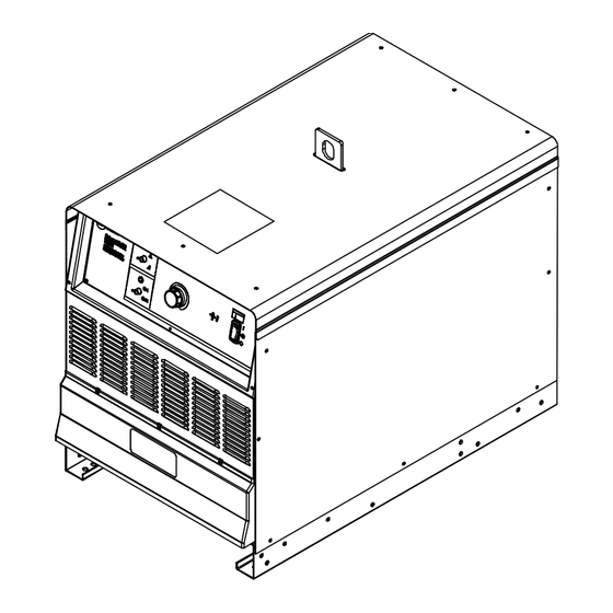
SECTION 5 – INSTALLATION 5-1. Dimensions And Weights Dimensions 30 in. (762 mm) Including lift eye 23 in. (584 mm) 38 in. (965 mm) Including strain relief 33-3/4 in. (857 mm) 1-1/4 in. (32 mm) 20 in. (508 mm) 1-1/8 in. (29 mm) 7/16 in. -
Page 26: Selecting A Location
Writers: Remember to move unit dimension and weight and rating la- bel location information to the appropriate sections. 5-2. Selecting A Location 1-3. Selecting A Location A complete Parts List is available at www.MillerWelds.com Do not move or operate unit where nit dimension and weight and rating la- Movement Writers: Remember to move unit dimension and weight and rating la-... -
Page 27: Electrical Service Guide
5-4. Electrical Service Guide A. Electrical Service Guide For DC 650/800 Digital Models Failure to follow these electrical service guide recommendations could create an electric shock or fire hazard. These recommen- dations are for an individual branch circuit sized for the rated output and duty cycle of one welding power source. In individual branch circuit installations, the National Electrical Code (NEC) allows the receptacle or conductor rating to be less than the rating of the circuit protection device. - Page 28 B. Electrical Service Guide For DC 1000/1250 Digital Models Failure to follow these electrical service guide recommendations could create an electric shock or fire hazard. These recommen- dations are for an individual branch circuit sized for the rated output and duty cycle of one welding power source. In individual branch circuit installations, the National Electrical Code (NEC) allows the receptacle or conductor rating to be less than the rating of the circuit protection device.
-
Page 29: Placing Jumper Links
5-5. Placing Jumper Links DC 650/800 Digital Model Shown 193546-A 193526-A philips head wrench crescent wrench Ref. 265207-A 3/8 in. ps head wrench crescent wrench 3/8 in. 1 Jumper Link Label For DC 800 Digital Move jumper links to match input voltage. Disconnect and lockout/tagout input nutdriver and DC 1250 Digital Machines... -
Page 30: Connecting 3-Phase Input Power For Dc 650/800 Models
5-6. Connecting 3-Phase Input Power For DC 650/800 Models = GND/PE Earth Ground tools/ n_set flathead philips head wrench crescent wrench = GND/PE Earth Ground tools/ tools/ ols/ Ref. input3 2015--01--Ref. 803766-C / 800103-D / Ref. 801116-A 5/32 in. 3/8, 1/2 in. 3/8 in. -
Page 31: Connecting 3-Phase Input Power For Dc 650/800 Models (Continued)
5-7. Connecting 3-Phase Input Power For DC 650/800 Models (Continued) Welding Power Source Input Power Disconnect Device Input Power Installation must meet all National Connections Connections and Local Codes − have only quali- fied persons make this installation. 2 Strain Relief (Customer Supplied) 7 Disconnect Device (switch shown in OFF Disconnect and lockout/tagout input position) -
Page 32: Connecting 3-Phase Input Power For Dc 1000/1250 Models
5-8. Connecting 3-Phase Input Power For DC 1000/1250 Models = GND/PE Earth Ground tools/ allen_wrench allen_set flathead philips head wrench IMPORTANT Input Terminal Board pliers L2 (V) needlenose knife steelbrush nutdriver L1 (U) L3 (W) tools/ solderiron heavy-duty workclamp light-duty workclamp wirecutter stripcrimp GND/PE... -
Page 33: Connecting 3-Phase Input Power For Dc 1000/1250 Models (Continued)
5-9. Connecting 3-Phase Input Power For DC 1000/1250 Models (Continued) Installation must meet all National Welding Power Source Input Power 6 Disconnect Device (switch shown in OFF and Local Codes − have only quali- Connections position) fied persons make this installation. 7 Disconnect Device (Supply) Grounding 2 Strain Relief (Customer Supplied) Disconnect and lockout/tagout input... -
Page 34: Section 6 - System Connections
SECTION 6 – SYSTEM CONNECTIONS 6-1. Terminal Strip TE2 and Receptacle RC1 Information Socket On Terminal On Function Contact Information A, B 24 VAC. Protected by circuit breaker CB2. Electrical Input Power C, D 24 VAC common. +Accessory RS- 485 communication. Accessory Serial Communication -Accessory RS- 485 communication. -
Page 35: Terminal Strip Te1
6-2. Terminal Strip TE1 Turn off welding power source be- fore opening access door. 1 Access Hole Remove knockout or cover from access hole and install customer supplied strain relief. Route cable connections through the access hole. 2 12–Pole Terminal Strip 3 Label Remove and retain screws and open ter- minal strip panel. -
Page 36: Section 7 - Making Weld Output Connections
SECTION 7 – MAKING WELD OUTPUT CONNECTIONS 7-1. Weld Output Terminals And Selecting Cables Sizes* NOTICE – The Total Cable Length in Weld Circuit (see table below) is the combined length of both weld cables. For example, if the power source is 100 ft (30 m) from the workpiece, the total cable length in the weld circuit is 200 ft (2 cables x 100 ft). -
Page 37: Weld Output Terminals
7-2. Weld Output Terminals Turn off power before connecting to weld output terminals. Do not use worn, damaged, under- sized, or repaired cables. 1 Positive (+) Weld Output Terminal 2 Negative (−) Weld Output Terminal � For welding output terminal connec- tions see Sections 7-4 and 7-5. -
Page 38: Basic Subarc (Saw) Welding
7-4. Basic SubArc (SAW) Welding � Customer must supply the following: power source, power source control cable, wire drive assembly, wire drive extension cable, drive rolls, torch, welding wire, weld cables, remote voltage sense leads, flux hopper, flux hopper extension cable, and flux system for the desired application. - Page 39 B. Remote Voltage Sensing Leads Placement Guidelines For A Single Arc (Required) Electrode Remote Voltage Sense Lead Work Remote Voltage Sense Lead Wire Drive Sense lead is affected by weld Welding Power current. Source Due to voltage drops across work piece, arc voltage may be low, causing need for deviation from standard procedures.
- Page 40 C. Sensing Lead Placement Guidelines For Multiple Arcs Lead Wire Drive Welding Power Source Wire Electrode Remote Drive Volt Sense Leads Work Current flow from lead affects trail Remote Voltage sense. Sense Leads Current flow from trail affects lead Lead Trail sense.
- Page 41 D. Basic SubArc SAW Equipment Connections For DCEN Flux System SubArc Interface Electrode Volt-sense Lead From Motor Cable Motor Extension Cable Wire Drive Assembly From Terminal Strip TE2 Terminal N From Terminal Strip TE2 Terminal P Workpiece Weld Cable Ref. 254240-A Turn off welding power source and �...
-
Page 42: Typical Connection For Cac-A Process
7-5. Typical Connection For CAC-A Process 272583-B For CAC-A process connect carbon arc cut- Connect work lead to negative (–) output Turn off welding power source and ting torch to positive (+) weld terminal. terminal. weld control before making connections. 3 Compressed Air Line 5 Workpiece 1 DC Power Source... -
Page 43: Connecting Multiple Units
7-6. Connecting Multiple Units Parallel Connections For Digital 650/800 Machines: FOLLOWING UNIT(S) CONTROLLING UNIT (WHITE) (WHITE) TO WORK TO WORK To RC1 ON NEXT DC 650 Digital UNIT WHITE (OR DC 800 Digital UNIT IF PARALLELING 800”S) TO ELECTRODE 254241-A Parallel Connections For Digital 1000/1250 Machines: FOLLOWING UNIT(S) CONTROLLING UNIT... -
Page 44: Section 8 - Power Source Operation
SECTION 8 – POWER SOURCE OPERATION 8-1. Controls PROCESS OUTPUT A/V ADJUST 262962-B Turn off welding power source and It is disabled if the power source is a follow- 4 Amperage/Voltage Adjustment Control weld control before making ing unit in parallel configuration. connections. -
Page 45: Section 9 - Plc Operation
SECTION 9 – PLC OPERATION 9-1. Automation Interface Hardware Configuration (PLC Users Only) Disconnect and lockout/tagout in- put power before connecting input conductors from unit. Follow es- tablished procedures regarding the installation and removal of lock/out tagout devices. 1 Switch DIP 1 Configure switch DIP 1 on Automation Inter- face board PC4 to match the network baud rate and parity settings, and set the MOD-... -
Page 46: Example Power Source Operation Using A Plc
9-3. Example Power Source Operation Using A PLC 4 Set all relevant parameters (MODBUS 7 Disable weld output by clearing the Out- 1 To enable welding control from the Auto- Holding Registers 102-107) to their de- put Enable Flag to 0 in the Command mation Interface, set the “Automation En- sired values. - Page 47 Table 9-8. Input Registers Register Address MODBUS Register Name Register Description Command Flags Weld Voltage Command Weld Current Command Weld Wire Speed Used for holding register verification (see Table 9-6). Weld Mode Run-In Speed Percentage Burn Back Time Drive Roll Diameter System Feedback Values Status Flags See Table 9-9.
- Page 48 Table 9-10. Weld Mode Look Up Table Line Input Frequency (Hz) Mode Balance 60 Hz Line 50 Hz Line Weld Mode Code Electrode Positive −− −− 0x0000 CV+C Electrode Positive −− −− 0x4000 Electrode Positive −− −− 0x8000 OM-265363 Page 42...
-
Page 49: Section 10 - Maintenance And Troubleshooting
SECTION 10 – MAINTENANCE AND TROUBLESHOOTING 10-1. SubArc System Help Codes SubArc Interface SubArc Power Fault Description Digital Help Code SourceStatus/Trouble Light � � Each flash sequence will be HELP will display in the followed by a one second upper display, and the code pause. - Page 50 4 Quick, 4 Slow Motor Low Bus Indicates bus voltage in SubArc Interface is low. 24 VAC from power source may be low if input primary line voltage is too low or, for DC power sources, power source could be incorrectly linked.
- Page 51 7 Quick, 1 Slow Invalid Model Type If paralleling units, firmware in controlling power source does not match firmware in the follow- ing power source. Update firm- ware in both machines to the latest revision. If code continues to display, contact nearest Fac- tory Authorized Service Agent.
-
Page 52: 10-2. Routine Maintenance
10-2. Routine Maintenance Disconnect power before maintaining. � Service equipment more often if used in severe conditions. Maintenance Schedule Every 3 Months Every 6 Months Cords and Cables Visually Check condition of cords and cables. � Replace damaged cords and cables. Cracked Parts Replace damaged parts. -
Page 53: 10-4. Troubleshooting Table
10-4. Troubleshooting Table Trouble Remedy No weld output; unit completely inop- Place line disconnect switch in On position (see Section 5-6 or 5-8). erative; power switch light off. Check for open line fuse(s), and replace if open (see Section 5-6 or 5-8). Check for proper input power connections (see Section 5-6 or 5-8). -
Page 54: Section 11 - Electrical Diagrams
SECTION 11 – ELECTRICAL DIAGRAMS Figure 11-1. Circuit Diagram For DC 650/800 Models Eff. w/ME210002G OM-265363 Page 48... - Page 55 OM-265363 Page 49...
- Page 56 Figure 11-2. Circuit Diagram For DC 1000/1250 Models Eff. w/ME210002G OM-265363 Page 50...
- Page 57 262521-F OM-265363 Page 51...
- Page 58 Notes...
- Page 59 Notes...
-
Page 60: Owner's Record
Appleton, WI 54914 USA tact your distributor and/or equipment manu- facturer’s Transportation Department. International Headquarters–USA USA Phone: 920-735-4505 USA & Canada FAX: 920-735-4134 International FAX: 920-735-4125 For International Locations Visit www.MillerWelds.com ORIGINAL INSTRUCTIONS – PRINTED IN USA © Miller Electric Mfg. LLC 2023-12...
Need help?
Do you have a question about the SubArc DC 650 DIGITAL and is the answer not in the manual?
Questions and answers