
Miller Subarc DC 1000 Manuals
Manuals and User Guides for Miller Subarc DC 1000. We have 4 Miller Subarc DC 1000 manuals available for free PDF download: Owner's Manual
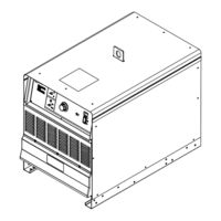
Miller Subarc DC 1000 Owner's Manual (60 pages)
Digital Power Sources
Brand: Miller
|
Category: Welding System
|
Size: 4 MB
Table of Contents
Advertisement
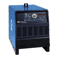
Miller Subarc DC 1000 Owner's Manual (56 pages)
Digital Power Sources
Brand: Miller
|
Category: Portable Generator
|
Size: 1 MB
Table of Contents

Miller Subarc DC 1000 Owner's Manual (56 pages)
Digital Power Sources
Brand: Miller
|
Category: Power Supply
|
Size: 1 MB
Table of Contents
Advertisement

Miller Subarc DC 1000 Owner's Manual (48 pages)
Brand: Miller
|
Category: Welding System
|
Size: 1 MB
Table of Contents
Advertisement