Table of Contents
Advertisement
Quick Links
For product information,
Owner's Manual translations,
and more, visit
www.MillerWelds.com
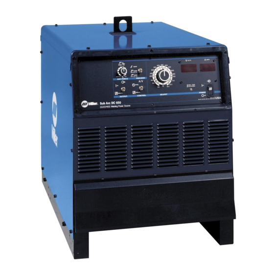
SubArc DC 650, 1000
SubArc DC 800 CE, 1250 CE
Digital Power Sources
OM-265363Q
Processes
Submerged Arc (SAW) Welding
Electroslag (ESW) Welding
Air Carbon Arc (CAC-A)
Cutting and Gouging
Description
Arc Welding Power Source
File: Submerged (SAW)
2020-10
Advertisement
Table of Contents
Troubleshooting

Related Manuals for Miller SubArc DC 650


Summary of Contents for Miller SubArc DC 650
- Page 1 Submerged Arc (SAW) Welding Electroslag (ESW) Welding Air Carbon Arc (CAC-A) Cutting and Gouging Description Arc Welding Power Source SubArc DC 650, 1000 SubArc DC 800 CE, 1250 CE Digital Power Sources For product information, File: Submerged (SAW) Owner’s Manual translations, and more, visit www.MillerWelds.com...
- Page 2 We know you don’t have time to do it any other way. That’s why when Niels Miller first started building arc welders in 1929, he made sure his products offered long-lasting value and superior quality.
-
Page 3: Table Of Contents
TABLE OF CONTENTS SECTION 1 − SAFETY PRECAUTIONS - READ BEFORE USING ....... . . 1-1. - Page 4 TABLE OF CONTENTS SECTION 10 − MAINTENANCE AND TROUBLESHOOTING ........10-1.
- Page 5 DECLARATION OF CONFORMITY for European Community (CE marked) products. MILLER Electric Mfg. Co., 1635 Spencer Street, Appleton, WI 54914 U.S.A. declares that the product(s) identified in this declaration conform to the essential requirements and provisions of the stated Council Directive(s) and Standard(s).
- Page 6 Product Stock Number SUBARC DC 1250 DIGITAL 907625 SUBARC DC 1000 DIGITAL 907624 SUBARC DC 800 DIGITAL 907623 SUBARC DC 650 DIGITAL 907622 Compliance Information Summary Applicable regulation Directive 2014/35/EU Reference limits Directive 2013/35/EU, Recommendation 1999/519/EC Applicable standards IEC 62822-1:2016, IEC 62822-2:2016...
-
Page 7: Section 1 − Safety Precautions - Read Before Using
SECTION 1 − SAFETY PRECAUTIONS - READ BEFORE USING som 2020−02 Protect yourself and others from injury — read, follow, and save these important safety precautions and operating instructions. 1-1. Symbol Usage DANGER! − Indicates a hazardous situation which, if Indicates special instructions. - Page 8 D Do not cut or weld on tire rims or wheels. Tires can explode if heat- FUMES AND GASES can be hazardous. ed. Repaired rims and wheels can fail. See OSHA 29 CFR 1910.177 listed in Safety Standards. D Do not weld on containers that have held combustibles, or on Welding produces fumes and gases.
-
Page 9: Additional Hazards For Installation, Operation, And Maintenance
D Never weld on a pressurized cylinder − explosion will result. CYLINDERS can explode if damaged. D Use only correct compressed gas cylinders, regulators, hoses, and fittings designed for the specific application; maintain them Compressed gas cylinders contain gas under high and associated parts in good condition. -
Page 10: California Proposition 65 Warnings
H.F. RADIATION can cause interference. ARC WELDING can cause interference. D High-frequency (H.F.) can interfere with radio D Electromagnetic energy can interfere with navigation, safety services, computers, and sensitive electronic equipment such as communications equipment. computers and computer-driven equipment such as robots. D Have only qualified persons familiar with electronic equipment D Be sure all equipment in the welding area is electromagnetically perform this installation. -
Page 11: Section 2 − Consignes De Sécurité − Lire Avant Utilisation
SECTION 2 − CONSIGNES DE SÉCURITÉ − LIRE AVANT UTILISATION som_2020−02_fre Pour écarter les risques de blessure pour vous−même et pour autrui — lire, appliquer et ranger en lieu sûr ces consignes relatives aux précautions de sécurité et au mode opératoire. 2-1. - Page 12 D Déplacer toutes les substances inflammables à une distance de LES PIÈCES CHAUDES peuvent 10,7 m de l’arc de soudage. En cas d’impossibilité les recouvrir provoquer des brûlures. soigneusement avec des protections homologués. D Ne pas toucher à mains nues les parties chaudes. D Ne pas souder dans un endroit là...
-
Page 13: Dangers Supplémentaires En Relation Avec L'installation, Le Fonctionnement Et La Maintenance
D Protéger les bouteilles de gaz comprimé d’une chaleur excessive, Les CHAMPS ÉLECTROMAGNÉTIQUES (CEM) des chocs mécaniques, des dommages physiques, du laitier, des peuvent affecter les implants médicaux. flammes ouvertes, des étincelles et des arcs. D Placer les bouteilles debout en les fixant dans un support station- D Les porteurs de stimulateurs cardiaques et naire ou dans un porte-bouteilles pour les empêcher de tomber ou autres implants médicaux doivent rester à... -
Page 14: Proposition Californienne 65 Avertissements
D Effectuer régulièrement le contrôle et l’entretien de l’installation. LIRE LES INSTRUCTIONS. D Maintenir soigneusement fermés les portes et les panneaux des sources de haute fréquence, maintenir les éclateurs à une distan- D Lire et appliquer les instructions sur les ce correcte et utiliser une terre et un blindage pour réduire les étiquettes et le Mode d’emploi avant l’instal- interférences éventuelles. -
Page 15: Section 3 − Definitions
A complete Parts List is available at www.MillerWelds.com SECTION 3 − DEFINITIONS 3-1. Additional Safety Symbols And Definitions Some symbols are found only on CE products. Warning! Watch Out! There are possible hazards as shown by the symbols. Safe1 2012−05 Wear dry insulating gloves. - Page 16 A complete Parts List is available at www.MillerWelds.com Do not remove or paint over (cover) the label. Safe20 2017−04 Disconnect input plug or power before working on machine. Safe30 2012−05 Consult rating label for input power requirements. Safe34 2012−05 Read Owner’s Manual and inside labels for connection points and procedures. Í...
-
Page 17: Miscellaneous Symbols And Definitions
A complete Parts List is available at www.MillerWelds.com 3-2. Miscellaneous Symbols And Definitions Some symbols are found only on CE products. Shielded Metal Amperage Duty Cycle Arc Welding (SMAW) Degree Of Gas Tungsten Arc Voltage Protection Welding (GTAW) Suitable For Submerged Arc Hertz Welding In An... -
Page 18: Section 4 − Specifications
4-3. Information About Default Weld Parameters And Settings NOTICE − Each welding application is unique. Although certain Miller Electric products are designed to determine and default to certain typical welding parameters and settings based upon specific and relatively limited application variables input by the end user, such default settings are for reference purposes only;... -
Page 19: Static Characteristics
A complete Parts List is available at www.MillerWelds.com 4-6. Static Characteristics The static (output) characteristics of the welding power source can be described as drooping during the SAW process. Static characteristics are also affected by control settings (including software), electrode, shielding gas, weldment material, and other factors. Contact the factory for specific information on the static characteristics of the welding power source. -
Page 20: Duty Cycle And Overheating
A complete Parts List is available at www.MillerWelds.com 4-8. Duty Cycle And Overheating A. Duty Cycle And Overheating For DC 650/800 Amp Models Duty Cycle is percentage of 10 min- utes that unit can weld at rated load without overheating. If unit overheats, thermostat(s) opens, output stops, and cooling fan runs. -
Page 21: Section 5 − Installation
A complete Parts List is available at www.MillerWelds.com SECTION 5 − INSTALLATION 5-1. Dimensions And Weights Dimensions 30 in. (762 mm) Including lift eye 23 in. (584 mm) 38 in. (965 mm) Including strain relief 33-3/4 in. (857 mm) 1-1/4 in. (32 mm) 20 in. -
Page 22: Selecting A Location
A complete Parts List is available at www.MillerWelds.com 5-2. Selecting A Location Movement Do not move or operate unit where it could tip. Location And Airflow Special installation may be required where gasoline or volatile liquids are present − see NEC Article 511 or CEC Section 20. -
Page 23: Electrical Service Guide
A complete Parts List is available at www.MillerWelds.com 5-4. Electrical Service Guide Elec Serv 2020−02 A. Electrical Service Guide For DC 650/800 Digital Models (Three-Phase) Failure to follow these electrical service guide recommendations could create an electric shock or fire hazard. These recommenda- tions are for a dedicated circuit sized for the rated output and duty cycle of the welding power source. - Page 24 A complete Parts List is available at www.MillerWelds.com B. Electrical Service Guide For DC 1000/1250 Digital Models (Three-Phase) Failure to follow these electrical service guide recommendations could create an electric shock or fire hazard. These recommenda- tions are for a dedicated circuit sized for the rated output and duty cycle of the welding power source. In dedicated circuit installations, the National Electrical Code (NEC) allows the receptacle or conductor rating to be less than the rating of the circuit protection device.
-
Page 25: Placing Jumper Links
A complete Parts List is available at www.MillerWelds.com 5-5. Placing Jumper Links Disconnect and lockout/tagout input power before installing or moving jumper links. Follow established procedures garding the installation and re- moval lockout/tagout devices. Check input voltage available at site. Jumper Link Label For DC 800 DC 650/800 Digital Models Digital and DC 1250 Digital... -
Page 26: Connecting 3-Phase Input Power
A complete Parts List is available at www.MillerWelds.com 5-6. Connecting 3-Phase Input Power = GND/PE Earth Ground GND/ PE Earth Ground Tools Needed: 5/32 in. 3/8, 1/2 in. 3/8 in. Ref. input3 2015−01 − Ref. 803766-C / 800103-D / Ref. 801116-A OM-265363 Page 20... - Page 27 A complete Parts List is available at www.MillerWelds.com 5-6. Connecting 3-Phase Input Power (Continued) applicable, use lugs of proper amperage Close and secure access door on welding Installation must meet all National capacity and correct hole size. power source. and Local Codes − have only qualified persons make this installation.
-
Page 28: Section 6 − System Connections
A complete Parts List is available at www.MillerWelds.com SECTION 6 − SYSTEM CONNECTIONS 6-1. Terminal Strip TE2 and Remote Receptacle RC1 Information Function Socket On RC1 Terminal On TE2 Contact Information Electrical Input Power A, B − 24 VAC. Protected by circuit breaker CB2. C, D −... -
Page 29: Terminal Strip Te1
A complete Parts List is available at www.MillerWelds.com 6-2. Terminal Strip TE1 Turn Off welding power source before opening access door. Access Hole Remove knockout or cover from access hole and install customer supplied strain relief. Route cable connections through the access hole. -
Page 30: Section 7 − Making Weld Output Connections
A complete Parts List is available at www.MillerWelds.com SECTION 7 − MAKING WELD OUTPUT CONNECTIONS 7-1. Weld Output Terminals And Selecting Cable Sizes* NOTICE − The Total Cable Length in Weld Circuit (see table below) is the combined length of both weld cables. For example, if the power source is 100 ft (30 m) from the workpiece, the total cable length in the weld circuit is 200 ft (2 cables x 100 ft). -
Page 31: Connecting Weld Output Cables
A complete Parts List is available at www.MillerWelds.com 7-3. Connecting Weld Output Cables Tools Needed: 3/4 in. (19 mm) 803778-B cable terminal and copper bar. Make Weld Cable Terminal Turn off power before connecting to sure that the surfaces of the weld cable weld output terminals. -
Page 32: Basic Subarc (Saw) Welding
A complete Parts List is available at www.MillerWelds.com 7-4. Basic Subarc (SAW) Welding Customer must supply the following: power source, power source control cable, wire drive assembly, wire drive extension cable, drive rolls, torch, welding wire, weld cables, remote voltage sense leads, flux hopper, flux hopper extension cable, and flux system for the desired application. A. - Page 33 A complete Parts List is available at www.MillerWelds.com B. Remote Voltage Sensing Leads Placement Guidelines For A Single Arc (Required) Electrode Remote Voltage Sense Lead Work Remote Voltage Sense Lead Wire Drive Sense lead is affected by weld Welding Power current.
- Page 34 A complete Parts List is available at www.MillerWelds.com C. Sensing Leads Placement Guidelines For Multiple Arcs Lead Wire Drive Welding Power Wire Source Electrode Remote Drive Volt Sense Leads Work Current flow from lead affects trail Remote Voltage sense. Sense Leads Current flow from trail affects lead Lead Trail...
- Page 35 A complete Parts List is available at www.MillerWelds.com D. Basic SubArc (SAW) Equipment Connections For DCEN Turn off welding power source and weld control before making connections. Use remote voltage sense leads in all applications. Suggested size for remote volt- age sense wire is 12 gauge or larger.
-
Page 36: Typical Connection For Cac-A Process
A complete Parts List is available at www.MillerWelds.com 7-5. Typical Connection For CAC-A Process 272583-B Electrode Holder (Carbon Arc) Work Lead Turn off welding power source be- fore making connections. For CAC-A process connect carbon arc Connect work lead to negative (−) output cutting torch to positive (+) weld terminal. -
Page 37: Connecting Multiple Units
A complete Parts List is available at www.MillerWelds.com 7-6. Connecting Multiple Units Turn Off welding power source before making connections. NOTICE − If there are any ques- tions regarding the paralleling pro- cedure, contact the factory before Parallel Connections For Digital 650/800 Machines: connecting units. -
Page 38: Section 8 − Power Source Operation
A complete Parts List is available at www.MillerWelds.com SECTION 8 − POWER SOURCE OPERATION 8-1. Controls PROCESS OUTPUT A/V ADJUST 262962-B Process Selector Switch Amperage/Voltage Adjustment Control Output is on and weld output studs Place switch in position for desired process. are energized when LED is lit. -
Page 39: Section 9 − Plc Operation
A complete Parts List is available at www.MillerWelds.com SECTION 9 − PLC OPERATION 9-1. Automation Interface Hardware Configuration (PLC Users Only) Disconnect and lockout/tag- out input power before con- necting input conductors from unit. Follow established pro- cedures regarding the install- ation and removal of lockout/ tagout devices. -
Page 40: Connection To Plc
A complete Parts List is available at www.MillerWelds.com 9-2. Connection To PLC The automation interface uses an RJ45 connector to communicate MODBUS RTU over RS485. The automation interface is NOT an Ethernet connection! The pin connections are as follows: Table 9-4. Connector Pinout Function RJ45 Pin Circuit... - Page 41 A complete Parts List is available at www.MillerWelds.com Table 9-7. Command Flags (MODBUS 101) Flag Name Bitmask Description Output Enable 0x0001 Enable Weld Output Wire Jog Up 0x0002 Feed Wire Up Wire Jog Down 0x0004 Feed Wire Down Flux On 0x0008 Open Flux Valve Motor CW...
- Page 42 A complete Parts List is available at www.MillerWelds.com Table 9-9. Status Flags (MODBUS 201) Flag Name Bitmask Description Valid Arc 0x0001 A valid arc has been detected. Output On 0x0002 The power source output is on. Run In 0x0004 The power source is in Run In. Weld 0x0008 The power source is in the weld state.
-
Page 43: Section 10 − Maintenance And Troubleshooting
A complete Parts List is available at www.MillerWelds.com SECTION 10 − MAINTENANCE AND TROUBLESHOOTING 10-1. SubArc System Help Codes SubArc Interface SubArc Power Source Sta- Fault Description Digital Help Code tus/Trouble Light HELP will dis- Each flash sequence will play in the up- be followed by a one sec- display, ond pause. - Page 44 A complete Parts List is available at www.MillerWelds.com 10-1. SubArc System Help Codes (Continued) SubArc Interface SubArc Power Source Sta- Fault Description Digital Help Code tus/Trouble Light HELP will dis- Each flash sequence will play in the up- be followed by a one sec- display, ond pause.
-
Page 45: Power Source Routine Maintenance
A complete Parts List is available at www.MillerWelds.com 10-2. Power Source Routine Maintenance Maintain more often during Disconnect input power severe conditions. before maintaining. n = Check Z = Change ~ = Clean Δ = Repair l = Replace * To be done by Factory Authorized Service Agent Every Months Δ... -
Page 46: Troubleshooting Table For Power Source
A complete Parts List is available at www.MillerWelds.com 10-4. Troubleshooting Table For Power Source Trouble Remedy No weld output; unit completely Place line disconnect device in On position (see Section 5-6). inoperative; power switch light off. Check for open line fuse(s), and replace if open (see Section 5-6). Check for proper input power connections (see Section 5-6). - Page 47 A complete Parts List is available at www.MillerWelds.com Notes MATERIAL THICKNESS GAUGE OM-265363 Page 41...
-
Page 48: Section 11 − Electrical Diagram
SECTION 11 − ELECTRICAL DIAGRAM Figure 11-1. Circuit Diagram For DC 650/800 Models Eff. W/ ME210002G OM-265363 Page 42... - Page 49 262523-E OM-265363 Page 43...
- Page 50 Figure 11-2. Circuit Diagram For DC 1000/1250 Models Eff. W/ME210002G OM-265363 Page 44...
- Page 51 262521-E OM-265363 Page 45...
- Page 52 Notes Welding Tip: Securely connect work clamp to a clean area close to the weld joint.
- Page 53 Notes MATERIAL THICKNESS REFERENCE CHART 24 Gauge (.025 in.) 22 Gauge (.031 in.) 20 Gauge (.037 in.) 18 Gauge (.050 in.) 16 Gauge (.063 in.) 14 Gauge (.078 in.) 1/8 in. (.125 in.) 3/16 in. (.188 in.) 1/4 in. (.25 in.) 5/16 in.
- Page 54 Notes...
- Page 55 Effective January 1, 2020 (Equipment with a serial number preface of NA or newer) This limited warranty supersedes all previous Miller warranties and is exclusive with no other guarantees or warranties expressed or implied. LIMITED WARRANTY − Subject to the terms and conditions...
- Page 56 Contact the Delivering Carrier to: File a claim for loss or damage during shipment. For assistance in filing or settling claims, contact your distributor and/or equipment manufacturer’s Transportation Department. © ORIGINAL INSTRUCTIONS − PRINTED IN USA 2020 Miller Electric Mfg. LLC 2020−01...
Need help?
Do you have a question about the SubArc DC 650 and is the answer not in the manual?
Questions and answers