Table of Contents
Advertisement
For product information,
Owner's Manual translations,
and more, visit
For product information,
Owner's Manual translations,
www.MillerWelds.com
and more, visit
www.MillerWelds.com
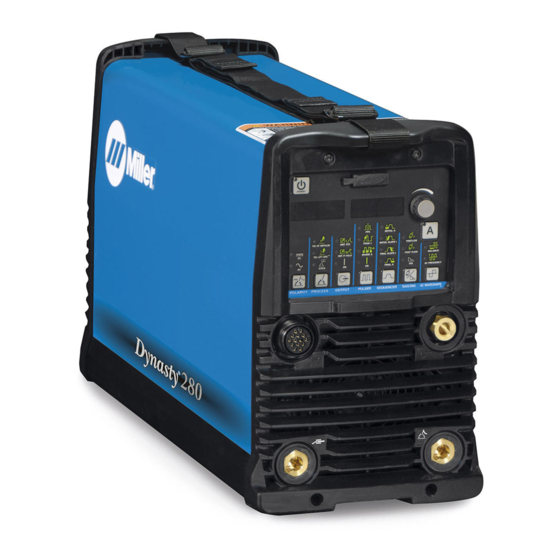
Dynasty 280, 280 DX
Dynasty
Dynasty 280 DX Multiprocess
Maxstar
Maxstar 280, 280 DX
CE And Non-CE Models
CE And Non-CE Models
OWNER'S MANUAL
OM-253086Z
OM-253086AA
Processes
Processes
TIG (GTAW) Welding
TIG (GTAW) Welding
Stick (SMAW) Welding
Stick (SMAW) Welding
MIG (GMAW) Welding
MIG (GMAW) Welding
Flux Cored (FCAW) Welding
Description
Flux Cored (FCAW) Welding
Description
208 575 Volt Models w/Autoline
Arc Welding Power Source
280–575 Volt Models w/Autoline Arc
Welding Power Source
280 Series
®
280 Series
®
2020-10
2021-06
Advertisement
Table of Contents
Troubleshooting


Need help?
Do you have a question about the Dynasty 280 Series and is the answer not in the manual?
Questions and answers
Amperage control not working,someone modified foot pedal ,think this the cause of issue
A modified foot pedal could cause an amperage control issue in a Miller Dynasty 280 Series if it does not properly match the machine’s remote potentiometer specifications. If the resistance or wiring is incorrect, the machine may not receive accurate amperage signals, leading to improper or no control of output.
This answer is automatically generated