Advertisement
Instructions-Parts
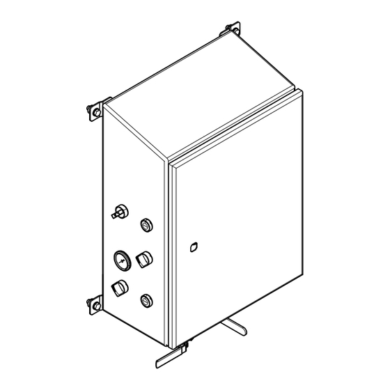
SaniForce™
SaniForce™ Pneumatic
SaniForce™
Integrated Pneumatic
Pneumatic Controls
Integrated
Integrated
Pneumatic
Important
Important Safety
Important
Safety Instructions
Safety
Read all warnings and instructions in this manual and the system
manuals. Save
Save all all all instructions.
Save
Maximum Working Air Pressure: 100
psi (0.7 MPa, 6.9 bar)
Pneumatic Controls
Pneumatic
Controls for
for use
use with
with Hygienic
Hygienic Unloader
Controls
for
use
with
Hygienic
Instructions
Instructions
instructions.
instructions.
PROVEN QUALITY. LEADING TECHNOLOGY.
Controls
Controls
Unloader Systems.
Systems. For
Unloader
Systems.
3A6101C
For professional
professional use
use only.
only.
For
professional
use
only.
EN
Advertisement
Table of Contents

Summary of Contents for Graco SaniForce SDU.A01AAA2AA0C21
- Page 1 Instructions-Parts SaniForce™ SaniForce™ SaniForce™ Pneumatic Pneumatic Controls Pneumatic Controls Controls 3A6101C Integrated Pneumatic Pneumatic Controls Controls for for use use with with Hygienic Hygienic Unloader Unloader Systems. Systems. For For professional professional use use only. only. Integrated Integrated Pneumatic Controls with Hygienic Unloader...
-
Page 2: Table Of Contents
Contents Contents Contents Models............... 2 25C578 Parts ............. 5 Pressure Relief Procedure ........3 25C543 Parts ............. 13 Switch Replacement ........... 4 California Proposition 65 ........19 Models Models Models Model Model Model Description Description Description Number Number Number 25C578 Pneumatic control panel, STU 25C543 Pneumatic control panel, SDU... -
Page 3: Pressure Relief Procedure
Pressure Relief Procedure Pressure Relief Relief Procedure Procedure Pressure Pressure Relief Procedure Follow the Pressure Relief Procedure whenever you see this symbol. 1. Follow the Pressure Relief Procedure in the system operation manual where this control panel is installed to place the system in a safe maintenance position before servicing the equipment. -
Page 4: Switch Replacement
Switch Replacement Switch Replacement Replacement Switch Switch Replacement To remove remove remove a a a switch switch from switch from the from the control control panel: control panel: panel: 1. Perform the pressure relief procedure. 2. Loosen the tension screw on the switch body (opposite side of switch body from tab T). -
Page 5: 25C578 Parts
25C578 Parts 25C578 Parts Parts 25C578 25C578 Parts Control Panel Panel 25C578 25C578 Control Control Panel 25C578 3A6101C... - Page 6 25C578 Parts Control Panel Panel 25C578 25C578 Control Control Panel 25C578 Qty. Qty. Ref. Part/Kit Part/Kit Description Description Description Qty. Qty. Ref. Part/Kit Part/Kit Description Description Description Qty. Qty. Ref. Ref. Part/Kit Ref. Ref. Part/Kit 17U557 ENCLOSURE 101754 PLUG 16V725 GAUGE, 0-30 psi 114373 FITTING, nipple 156593...
- Page 7 25C578 Parts Air Controls Controls Panel Panel Controls Panel 3A6101C...
- Page 8 25C578 Parts Air Controls Controls Panel Panel Controls Panel Qty. Qty. Ref. Part/Kit Part/Kit Description Description Description Qty. Qty. Ref. Part/Kit Part/Kit Description Description Description Qty. Qty. Ref. Ref. Part/Kit Ref. Ref. Part/Kit 17S206 PANEL 110460 FITTING 17T009 VALVE 114469 FITTING, elbow, swivel 17T002 VALVE...
-
Page 9: Component Panel
25C578 Parts Component Panel Panel Component Component Panel Component Panel Panel Component Component Panel Qty. Qty. Ref. Part/Kit Part/Kit Description Description Description Qty. Qty. Ref. Part/Kit Part/Kit Description Description Description Qty. Qty. Ref. Ref. Part/Kit Ref. Ref. Part/Kit 121 17S088 PANEL 129 114469 FITTING, elbow, swivel 122 17T269 REGULATOR... - Page 10 Schematic 25C578 25C578 Schematic Schematic 25C578...
- Page 11 25C578 Parts 25C578 Tubing Tubing Routing Routing 25C578 25C578 Tubing Routing Tubing Tubing requiring Tubing requiring additional requiring additional fittings. additional fittings. fittings. 3A6101C...
- Page 12 25C578 Parts Single Tubes Tubes Single Single Tubes TUBE TUBE PART TUBE PART NO. PART LENGTH LENGTH (inches) LENGTH (inches) (inches) FROM FROM FROM 15.5 V10 #2 Bulkhead #1 10.75 R3 IN R3 IN R4 IN 10.5 V3 #2 11.5 V3 #4 18.25 V12 #2...
-
Page 13: 25C543 Parts
25C543 Parts 25C543 Parts Parts 25C543 25C543 Parts Control Control Control Panel Panel 25C543 Panel 25C543 25C543 Control Control Panel Control Panel Panel 25C578 25C578 25C578 3A6101C... - Page 14 25C543 Parts Description Description Description Qty. Qty. Qty. Description Description Description Qty. Qty. Qty. Ref. Ref. Part/Kit Ref. Part/Kit Part/Kit Ref. Ref. Ref. Part/Kit Part/Kit Part/Kit 17P914 ENCLOSURE 120389 FITTING, tube 25C542 PANEL 114316 FITTING, elbow, swivel 17W584 SWITCH, 3 position 070274 TAPE, TFE 17W583 SWITCH, 2 position...
- Page 15 25C543 Parts Component Panel Panel 25C542 25C542 Component Component Panel 25C542 3A6101C...
- Page 16 Schematic 25C543 25C543 Schematic Schematic 25C543 PUMP S LOW FAS T PRESSURE S LOW FAS T RELIEF VALVE 5/32" TUBE 100 P S I 5/32" TUBE PUMP 1/2" TUBE 1/2" TUBE PUMP J OG 3/8" TUBE 5/32" TUBE FREE FLOW HOLD DOWN DOWN...
- Page 17 25C543 Parts 25C543 Tubing Tubing Routing Routing 25C543 25C543 Tubing Routing NOTE: The numbers on this drawing correspond with the tubing from/to entries on the table on the next page. NOTE: NOTE: 3A6101C...
- Page 18 25C543 Parts Single Tubes Tubes Single Tubes Tubes Single Single Tubes Single Single Tubes TUBE TUBE TUBE LENGTH LENGTH LENGTH FROM FROM FROM TUBE TUBE TUBE LENGTH LENGTH LENGTH FROM FROM FROM Pt/No. Pt/No. Pt/No. (inches) Pt/No. Pt/No. Pt/No. (inches) (inches) (inches) (inches)
-
Page 19: California Proposition 65
California Proposition 65 California Proposition Proposition 65 California California Proposition CALIFORNIA RESIDENTS RESIDENTS CALIFORNIA CALIFORNIA RESIDENTS WARNING: Cancer and reproductive harm — www.P65warnings.ca.gov. WARNING: WARNING: 3A6101C... - Page 20 Graco to be defective. This warranty applies only when the equipment is installed, operated and maintained in accordance with Graco’s written recommendations. This warranty does not cover, and Graco shall not be liable for general wear and tear, or any malfunction, damage or wear caused by faulty installation, misapplication, abrasion, corrosion, inadequate or improper maintenance, negligence, accident, tampering, or substitution of non-Graco component parts.


Need help?
Do you have a question about the SaniForce SDU.A01AAA2AA0C21 and is the answer not in the manual?
Questions and answers