
Subscribe to Our Youtube Channel
Related Manuals for MSI Cubi 6 1M


Summary of Contents for MSI Cubi 6 1M
- Page 1 Cubi Series Personal Computer Cubi 6 1M (Cubi B0B1) Cubi 6 13MQ (Cubi B0B1) User Guide...
-
Page 2: Table Of Contents
Contents Getting Started ......................3 Package Contents ....................3 Safety & Comfort Tips .................... 3 System Dimension ....................4 System Overview..................... 5 Hardware Setup ...................... 9 Placing the System ....................13 Mainboard Components ..................14 Windows 11 System Operations ................20 Power Management ..................... -
Page 3: Getting Started
Getting Started This chapter provides you with the information on hardware setup procedures. While connecting devices, be careful in holding the devices and use a grounded wrist strap to avoid static electricity. Package Contents Personal Computer Cubi B0B1 Documentation Quick Start Guide (Optional) User Guide (Optional) Warranty Book (Optional) Accessories... -
Page 4: System Dimension
System Dimension... -
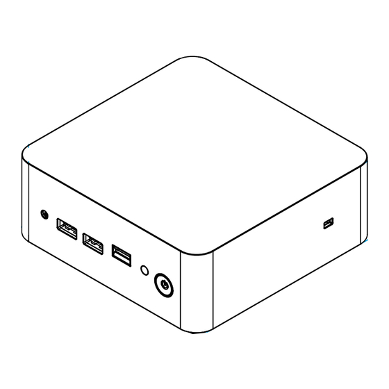
Page 5: System Overview
System Overview... - Page 6 Combo Audio Jack This connector is provided for headphones or speakers or microphones. USB 3.2 Gen 2 Port This connector is provided for USB peripheral devices. (Speed up to 10 Gbps) MicroSD Card Reader For MicroSD cards. Hard Disk Drive LED This indicator shows the activity status of the HDD.
- Page 7 Thunderbolt™ 4 Port (USB Type-C®) ∙ Supports up to 40Gbps transfer rate with Thunderbolt™ devices. ∙ Supports up to 20Gbps transfer rate with USB4™ devices. ∙ Supports up to 10Gbps transfer rate with USB 3.2 devices. ∙ Supports up to 5V/3A,15W power charging. ∙...
- Page 8 2.5 Gbps LAN Jack The standard RJ-45 LAN jack is provided for connection to the Local Area Network (LAN). You can connect a network cable to it. Status Description No link Link/ Yellow Linked Activity LED LINK/ACT SPEED Blinking Data activity 10 Mbps Speed LED Green...
-
Page 9: Hardware Setup
Hardware Setup Connect your peripheral devices to suitable ports. ⚠ Important ∙ For detailed instructions on how to connect, please refer to the manuals of your peripheral devices. ∙ Reference image only. Appearance will vary. Connecting Thunderbolt Devices via Daisy-chain (Optional) Daisy-chain is a method of connecting multiple devices to a PC with only one output terminal. - Page 10 Connect the power cord to the system and electrical outlet. ∙ External Power Supply: 120W, 19.5V • Input: 100~240Vac, 50/60Hz • Output: 19.5V 6.15A ⚠ Important When unplugging the AC power cord, always hold the connector part of the cord. Never pull the cord directly.
- Page 11 Press the power button to power on the system.
- Page 12 Connect the power button switch cable. (Optional)
-
Page 13: Placing The System
Placing the System Users can place the system horizontally or wall mount it. -
Page 14: Mainboard Components
Mainboard Components Front I/O JCL_CMOS1 JBD1 JDP1 MD2_2 SATA1 DIMM 1 USB2_1 DIMM 2 USB2_2 MD2_1 MD2_3 PWR_SW1 JBAT1 Rear I/O 125 mm... - Page 15 115 mm Front I/O 7 mm CPU_FAN1 JTPM1 Rear I/O 115 mm...
- Page 16 Front I/O Connectors Rear I/O Connectors 1. Power Button 5. Power Jack 2. MicroSD Card Reader 6. HDMI™ Connector 3. USB 3.2 Gen 2 Port 7. Thunderbolt™ 4 Port (USB-C®) 4. Combo Audio Jack 8. 2.5 Gbps LAN Jack...
- Page 17 Internal Headers & Connectors JCL_CMOS1: Clear CMOS jumper Signal Signal RTCRST# PWR_SW1: Power switch header Signal Signal PWRBTIN# JDP1: Debug header Signal Signal SIO_DEBUG VCC5 JBD1: BIOS debug header Signal Signal SOUTA USB2_1: USB2.0 header Signal Signal SVCC2 USBP8 USBN8 USB2_2: USB2.0 header Signal Signal...
- Page 18 SATA1: SATA connector Signal Signal SATA_TXP_0 VCC5 SATA_TXN_0 VCC5 VCC5 VCC5 SATA_RXN_0 VCC5 SATA_RXP_0 CPU_FAN1: CPU FAN connector Signal Signal SIO_CPU_FANTAC VCC5 SIO_CPU_FAN JTPM1: TPM module connector Signal Signal 3VSB PCH_SPI_CS2# EC_PLTRST_TPM# PCH_SPI_MISO SPI_SW_SEL PCH_SPI_MOSI PCH_SPI_CS# PCH_SPI_IO2 PCH_SPI_CLK SERIRQ...
- Page 19 Block Diagram...
-
Page 20: Windows 11 System Operations
Windows 11 System Operations ⚠ Important All information and Windows screenshots are subject to change without prior notice. Power Management Power management of personal computers (PCs) and monitors has the potential to save significant amounts of electricity as well as deliver environmental benefits. To be energy efficient, turn off your display or set your PC to sleep mode after a period of user inactivity. - Page 21 ∙ Tune the settings in Power Options under Windows OS to optimize your PC’s power management. ∙ Install power saving software to manage your PC’s energy consumption. ∙ Always disconnect the AC power cord or switch the wall socket off if your PC would be left unused for a certain time to achieve zero energy consumption.
-
Page 24: Network Connections
Network Connections Wi-Fi 1. Right-click [Start] and select [Network Connections] from the list. 2. Select and turn on [Wi-Fi]. 3. Select [Show available networks]. A list of available wireless networks pops up. Choose a connection from the list. 4. To establish a new connection, select [Manage known networks]. 5. - Page 27 Ethernet 1. Right-click [Start] and select [Network Connections] from the list. 2. Select [Ethernet]. 3. The [IP assignment] and [DNS server assignment] are automatically set as [Automatic (DHCP)]. 4. For a Static IP connection, click [Edit] of [IP assignment]. 5. Select [Manual]. 6.
- Page 30 Dial-up 1. Right-click [Start] and select [Network Connections] from the list. 2. Select [Dial-up]. 3. Select [Set up a new connection]. 4. Choose [Connect to the Internet] and click [Next]. 5. Select [Broadband (PPPoE)] to connect using DSL or cable that requires a user name and password.
-
Page 32: System Recovery
System Recovery The purposes for using the System Recovery Function may include: ∙ Restore the system back to the initial status of original manufacturer’s default settings. ∙ When some errors have occurred to the operating system in use. ∙ When the operating system is affected by virus and is not able to work normally. ∙... -
Page 34: F3 Hotkey Recovery (Optional)
Recovering the system with the F3 Hotkey Follow the instructions below to continue: 1. Restart the PC. 2. Press the F3 hotkey on the keyboard promptly when the MSI greeting appears on the display. 3. On the [Choose an option] screen, select [Troubleshoot]. -
Page 35: Safety Instructions
∙ Place the power cord in a way that people are unlikely to step on it. Do not place anything on the power cord. ∙ If this device comes with an adapter, use only the MSI provided AC adapter approved for use with this device. - Page 36 California, USA: The button cell battery may contain perchlorate material and requires special handling when recycled or disposed of in California. For further information please visit: https://dtsc.ca.gov/perchlorate/ Environment ∙ To reduce the possibility of heat-related injuries or of overheating the device, do not place the device on a soft, unsteady surface or obstruct its air ventilators.
-
Page 37: Regulatory Notices
∙ ErP Directive 2009/125/EC Compliance with these directives is assessed using applicable European Harmonized Standards. The point of contact for regulatory matters is MSI-Europe: Eindhoven 5706 5692 ER Son. Products with Radio Functionality (EMF) This product incorporates a radio transmitting and receiving device. For computers in normal use, a separation distance of 20 cm ensures that radio frequency exposure levels comply with EU requirements. -
Page 38: Fcc-B Radio Frequency Interference Statement
∙ this device may not cause harmful interference, and ∙ this device must accept any interference received, including interference that may cause undesired operation. MSI Computer Corp. 901 Canada Court, City of Industry, CA 91748, USA (626) 913-0828 www.msi.com WEEE Statement Under the European Union (“EU”) Directive on Waste Electrical and... -
Page 39: Chemical Substances Information
Vietnam RoHS As from December 1, 2012, all products manufactured by MSI comply with Circular 30/2011/TT-BCT temporarily regulating the permitted limits for a number of hazardous substances in electronic and electric products. -
Page 40: Green Product Features
∙ Users should contact the local authorized point of collection for recycling and disposing of their end-of-life products. ∙ Visit the MSI website and locate a nearby distributor for further recycling information. ∙ Users may also reach us at gpcontdev@msi.com for information regarding proper disposal, take-back, recycling, and disassembly of MSI products. -
Page 41: Copyright And Trademarks Notice
Copyright and Trademarks Notice Copyright © Micro-Star Int’l Co., Ltd. All rights reserved. The MSI logo used is a registered trademark of Micro-Star Int’l Co., Ltd. All other marks and names mentioned may be trademarks of their respective owners. No warranty as to accuracy or completeness is expressed or implied.
Need help?
Do you have a question about the Cubi 6 1M and is the answer not in the manual?
Questions and answers