Atlas Copco PAC Series Instruction Manual
Hide thumbs
Also See for PAC Series:
- Instruction manual (72 pages) ,
- Instruction book (48 pages) ,
- Instruction manual (68 pages)

Related Manuals for Atlas Copco PAC Series


Summary of Contents for Atlas Copco PAC Series
- Page 1 Instruction Manual Instruction manual for PAC Series Pump English PAC H86C FVL15 CNP ITH VOLVO TAD872VE...
- Page 3 PAC H86C FVL15 CNP ITH Instruction Manual for PAC Series Pump Instruction manual .................. 5 Circuit diagrams ..................58 Original instructions Printed matter No ATLAS COPCO - PORTABLE ENERGY DIVISION 2960 7920 00 www.atlascopco.com 06/2022...
- Page 4 While every effort has been made to ensure that the information in in this manual is correct, Atlas Copco does not assume responsibility for possible errors. Copyright 2022, Varisco S.r.L, PADOVA, ITALY. Any unauthorized use or copying of the contents or any part thereof is prohibited.This applies in particular to trademarks, model denominations, part numbers and drawings.
-
Page 5: Table Of Contents
Please read the following instructions carefully before starting to use your machine. While every effort has been made to ensure that the information in this manual is correct, Atlas Copco does not assume responsibility for possible errors. Atlas Copco reserves the right to make changes without prior notice. - Page 6 6.2.1 Overview of possible operating problems ...........52 Storage of the pump ..55 Storage ..........55 Preparing for operation after storage ..........55 Disposal ....56 General..........56 Disposal of materials .......56 Options .
-
Page 7: Safety Precautions For Pumps
The policy of Atlas Copco is to provide the users of their Atlas Copco equipment. It is the responsibility of unsafe operating conditions. Take necessary steps to equipment with safe, reliable and efficient products. -
Page 8: General Safety Precautions
covers shall be opened before sufficient cooling 15 When working on the unit, wear safety clothing. The manufacturer does not accept any liability for any damage arising from the use of non-original parts and for time has elapsed; this to avoid the risk of Depending on the kind of activities these are: modifications, additions or conversions made without spontaneous ignition of oil vapour when air is... -
Page 9: Safety During Transport And Installation
- check the towbar, the brake system and the via the holes in the frame at the front and back or consult Atlas Copco. towing eye. Also check the coupling of the via the lifting beam. To prevent damage, never 15. -
Page 10: Safety During Use And Operation
5. Never refill fuel while the unit is running, unless down equipment, do so with caution and use the noise hazardous area and an obvious warning otherwise stated in the Atlas Copco Instruction appropriate protection, at least safety glasses, for shall be placed permanently at each entrance Book (AIB). -
Page 11: Safety During Maintenance And Repair
15. Safety shoes should be compulsory in any sure that all electric connections are securely inadvertent starting. In addition, a warning sign workshop and if there is a risk, however small, tightened. bearing a legend such as "work in progress; do of falling objects, wearing of a safety helmet not start"... -
Page 12: Tool Applications Safety
20. Make sure that oil, solvents and other substances -never smoke near batteries being, or having recently recommended or approved by Atlas Copco or likely to pollute the environment are properly been, charged, the machine manufacturer. Ascertain that the disposed of. -
Page 13: Main Parts
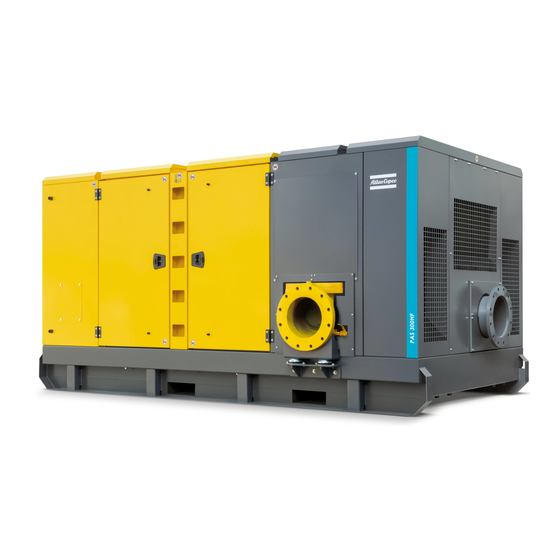
Main parts General description The PAC H86C dry-prime centrifugal pump is suitable for handling clean water or liquids up to 50°C. The PAC H86C pump is driven by a fluid-cooled diesel engine, manufactured by VOLVO. An overview of the main parts is given in the diagram below. Air filter Air separator Battery switch... - Page 14 Lifting beam Side doors Engine exhaust Data plate Hole for forklift Emergency stop button kit Fuel tank cap ADblue tank cap - 14 -...
-
Page 15: Flow Diagram
Flow Diagram - 15 -... -
Page 16: Markings
Markings CHECK Read the instruction manual Markings provide instructions and information. They Check engine oil daily. ENGINE before using the lifting eye. also warn of hazards. For convenience and safety, OIL DAILY keep all markings in legible condition, replacing them when damaged or missing. -
Page 17: Field Of Application
Despite the pump is able to deal with air in the suction pump is incorporated. line, Atlas Copco recommends to avoid this situation 2.4.4 Safety devices Vacuum created in the suction pipe by the vacuum as far as possible in order to guarantee a better pump, forces water to penetrate the pump. -
Page 18: Control Panel
2.4.5 Control panel 2.4.7 Drain plugs and filler caps Electrical features The control panel grouping the controller, hour meter, The drain holes for the engine oil, the coolant and the The electrical features described in this chapter are fuel level gauge, ON/OFF switch etc., is placed at the plug for the fuel, are located and labelled on the standard provided on this pump. -
Page 19: Control Panel Pw 750
Control panel PW 750 The control panel controls and automatically starts/stops governed diesel engine. Description Emergency stop button Pull the Emergency Stop button "OUT" to allow engine operation. Push the Emergency Stop button to shutdown the engine LCD displays SAE J1939 parameters and diagnostics. Configuration via display: transducer start-stop, transducer alarms, engine run speed, automatic start/stop mode. - Page 20 LED INDICATION MODEL PW750 AUTO STANDY LED (Green) An illuminated AUTO STANDBY LED indicates the keyswitch is in the "auto start" position and the system is ready to start. PREHEAT LED (Amber) An illuminated PREHEAT LED indicates the keyswitch is in the "auto start" position and the system is ready to start.
- Page 21 Description Float switch connector with cap. The control Panel uses a four position circular plastic connector for the two floats inputs switch. The control panel is equipped with a harness interface auxiliary interface I/O. Pin 1: High Float (colour cable GREY). Pin 2: Low Float (colour cable TANGERINE).
-
Page 22: Display Interface
2.6.1 Display interface Five buttons access a context dependent button bar when any button from 1 to 4 is pressed. The graphical menu structure uses easily understood icons to indicate the button's current function. After 5 seconds of inactivity the button bar disappears. Button 1: Analog Gauge (pages) Button 2: Digital Gauge (pages) Button 3: Single Analog gauge... - Page 23 ACTIVE ALARM Example Alarms message. After identification, the exit button becomes active. Standard J1939 abbreviations are used for alarms. SNP: Suspect Parameter Number. FMI: Failure Mode Indicator - 23 -...
- Page 24 ALARM LIST The Alarm List is accessed by pressing any button while an alarm popup is displayed or by pressing any of the first 4 buttons to show the button bar and then button 4 Alarms not yet acknowledged are shown in grey on black while acknowledged alarms are shown in black on grey.
- Page 25 ANALOG GAUGE PAGES DIGITAL GAUGE PAGES SIGLE ANALOG GAUGE Digital Gauge Pages display the same data as the Analog Gauge Pages give four indipendent pages of Analog Gauge Pages but in digital only format. To Single Analog Gauge uses the entire display for a analog gauges (16 total).
- Page 26 CONFIGURATION DISPLAY To adapt the control panel to the requirements of a The Display Menu allows the user to configure items particular application, a large number of parameters affecting how information is displayed. are configurable. This menu allows the user to set the units used for The "Configuration"...
- Page 27 LANGUAGE MENU BUTTON BEEP The soft buttons emit an audible beep when this item is On. Button beep is disabled by setting this item to Off. The audible beep still sounds when an alarm occurs. Button 4 cycles between On and Off. GAUGE Speed MPH (miles per hour) km/h (kilometers per hour)
- Page 28 SERVICE SYSTEM Pressing Button 4 allows adjusting the selected Sets the sixteen (16) service intervals in hours and The System Menu allows the user to configure items service timer. resets the service timer. Setting the service interval to affecting how the system functions. Button 4 cycles Button 1 decreases the service interval time, while 0 disables the timer and the word Off is displayed.
-
Page 29: Float Switches
Float switches Operating procedure: • The tank drains: The pump is fitted with two float switches for 1. Connect the float switches as follows: operation in Auto mode. These float switches must be • Connect the Start float to Connector indicated coupled to the connectors, located at the side of the by label “A Start float”. -
Page 30: Installation And Connection
Installation and connection Lifting To be able to lift the unit by means of a forklift, Installation rectangular slots are provided at the bottom of the Before lifting the unit, check its dimensions and frame. 3.2.1 Indoor installation weight, which can be found on the Data plate. If the pump is operated indoors, install an exhaust When lifting the unit, the hoist has to be placed in pipe of sufficient diameter to duct the engine exhaust... - Page 31 – Check that the inner earthing system is in compliance with the local legislation. – Use coolant for the engine cooling system. Refer to the Engine instruction book for the proper coolant mixture. – Check the tightness of the bolts and nuts. - 31 -...
-
Page 32: Suction And Discharge Pipework
In the same casing. way, bends in the suction should be avoided as much as possible. Atlas Copco recommends fluid velocities up to 2 m/s (6 ft/sec) on the suction and 3 m/s (9ft/sec) on the discharge. -
Page 33: Operating Instructions
Operating instructions perating instructions PW 750 – During operation, the various surfaces on the unit are hot. Signals indicate which areas are warmer. To avoid burn injury, use PPE (Personal Protective Equipment) and appropriate precautions. – During operation, do not refuel the engine or touch any moving parts. The pump may not be used in an explosive (inflammable environment or used to pump inflammable liquids. - Page 34 Users can attempt to rectify the fault by restoring factory defaults (pass on speed until the stop condition exists. Configuration Menu for details). Contact your local Atlas Copco dealer for assistance if the fault persists. After the start-up screen is cleared, the display shows readings on its virtual gauges.
- Page 35 SCR (SELECTIVE CATALYTIC REDUCTION) To meet the demands of Stage IV Emission Legislation, the engine is equipped with an exhaust aftertreatment system consisting of an exhaust gas recirculation system and a selective catalytic reduction system. The exhaust gas is fully automatically cleaned.
-
Page 36: Maintenance
Maintenance The maintenance schedule contains a summary of the maintenance instructions. Read the respective section before taking maintenance measures. For engine maintenance refer to Engine Operation Manual. The maintenance schedule has to be seen as a guideline for units operating in a dusty environment typical to the pump's applications. - Page 37 Function Group Task 4000 4500 5000 5500 6000 6500 7000 7500 8000 VODIA diagnostic tool (VOLVO) Check software status Check leakage Noise, engine / transmission Engine and transmission Start and warm up Cleaning / painting Hoses / cables, clamping Replace, check Flat belt Inspection Engine oil and filter...
-
Page 38: Pump Maintenance Procedures
Pump maintenance Residual liquid may be found in the procedures pump casing, head and suction line. Take the necessary precautions if liquid hazardous GENERAL RECOMMENDATIONS (inflammable, corrosive, poisonous, – Handling must be carried out by specialized infected). personnel to avoid damage to the pump and to persons. - Page 39 LUBRIFICATING THE PUMP LUBRIFICATING THE DIAPHRAGM VACUUM PUMP Every month check the oil level using indicators The vacuum pump is of diaphragm type; its (min. oil level, maximum oil level) and if necessary lubrication is oil bath type. to up through the cap (Ref. n°3). Running the vacuum pump with an insufficient MECHANICAL SEAL CHECK amount of oil can damage it.
-
Page 40: Adjustments And Service Procedures
Adjustments and service procedures 5.2.1 Positioning the impeller with 5.2.2 Inspection check valve - Valmatic reference to the wear plate(s) In all models, the distance between the top of the impeller blades and the surface of the wear plate must be between 0.3 - 0.6 mm To achieve this, dimensions A and B must be as nearly as possible equal. -
Page 41: Engine Maintenance Procedures Volvo Tad872Ve
Engine maintenance procedures VOLVO TAD872VE 5.3.2 Engine oil and oil filter change Refer to the Engine Operation Manual for a full – Install and tighten the drain plug on the oil drain maintenance schedule. flexible. Refer to the Engine Operation Manual for more –... -
Page 42: Replacing Fuel Filter Element
5.3.4 Servicing air filter engine 5.3.4.2 Recommendation 5.3.4.1 Main parts The Atlas Copco air filters are specially designed application. The use of non-genuine air filters may lead to severe damage of engine and/or alternator. Never run the unit without air filter element. -
Page 43: Replacing The Filter Element
5.3.5 Replacing the filter element New elements must also be inspected for tears or punctures before installation. 1. Release the snap clips (1) and remove the dust trap cover (2). Clean the inside of the cover. 2. Remove the element (3). 3. -
Page 44: Cleaning Cooler
5.3.6 Cleaning cooler 5.3.7 Cleaning the fuel tank – Steam cleaning in combination with a cleansing agent may be applied. To avoid damaging the coolers, angle between jet and coolers should be approx. 90°. Protect the electrical and controlling equipment, air filters, etc. against penetration of moisture. -
Page 45: Battery Care
5.3.8 Battery care – Rock the battery a few times so that possible air If a battery does not need any make-up water at all bubbles can escape; wait 10 minutes and check the over considerable time operation, Before handling batteries, read the level in each cell once more;... -
Page 46: Engine Consumable Specifications
ISO 3448, as follows: Specifications PAROIL retention and more alkalinity to control acid formation. PAROIL from Atlas Copco is the ONLY oil tested Engine Type of lubricant and approved for use in all engines built into Atlas PAROIL prevents Soot build-up. -
Page 47: Engine Coolant Specifications
Remove the cap slowly and only low as -25°C (-13°F). when coolant ambient Atlas Copco's PARCOOL EG extended life coolant is temperature. A sudden release of the new range of organic coolants purpose designed Order pressure from a heated cooling to meet the needs of modern engines. - Page 48 Order Litre cu.ft number 0.175 1604 5308 00 1604 5307 01 barrel 55.2 7.35 1604 5306 00 To ensure protection against corrosion, cavitation and formation of deposits, the concentration of the additives in the coolant must be kept between certain limits, as stated by the manufacturer's guidelines.
-
Page 49: Checks And Trouble Shooting
Checks and trouble shooting Engine troubleshooting Not enough power When a failure occurs, always – Restriction in a fuel pipe. The table below gives an overview of the possible report what you experienced before, engine problems and their possible causes. –... - Page 50 The pressure of the lubricating oil is too low – Incorrect valve tip clearances. – Fault in cold start system. – Wrong grade of lubricating oil. – Engine overload. – Restriction in fuel tank vent. – Not enough lubricating oil in sump. –...
-
Page 51: Pump Troubleshooting
Crankcase pressure Pump troubleshooting – Restriction in breather pipe. The paragraph reports the most common problems – Vacuum pipe leaks or fault in exhaust. that may occur during use of the pump and the possible remedies. Bad compression In case operation defects founded in the starting phase –... -
Page 52: Overview Of Possible Operating Problems
6.2.1 Overview of possible operating problems Symptom Possible cause Corrective action Pump does not prime 1. Suction tubes or inlet filter clogged. The Remove the obstruction. vacuum gauge indicates a high value. 2. Suction tube collapse. Use reinforced suction tube. 3. - Page 53 Low or no flow 1. The pump does not prime, See causes given in Pump does not prime. 2. Head required by the system is greater Revise system design or select a different pump. than the rated head of the pump. 3.
- Page 54 Pump does not provide enough pressure 1. Viscosity of the liquid is higher than Contact the pump manufacturer once you have measured the viscosity expected. of the liquid. Viscosity for centrifugal pumps should not exceed 50 cSt. Check for other possible causes: see Low or no flow. 2.
-
Page 55: Storage Of The Pump
Storage of the pump Storage Preparing for operation after storage – Store the pump in a dry, frost-free room which is well ventilated. Before operating the pump again, remove the wrapping. – Run the engine regularly, e.g. once a week, until it is warmed up. -
Page 56: Disposal
Support disposing professionally. assuring correct Your Atlas Copco pump consists mostly of metallic materials, that can be remelted in steel and melting disposal of the product you help prevent works and are therefore amost infinitely recyclable. possible negative consequences environment and health as a result of inappropriate waste handling. -
Page 57: Options
Options External fuel tank View inside connection (with/without quick couplings) The option external fuel tank connection allows to bypass the internal fuel tank and to connect an external fuel tank to the unit. View outside When using this option, make sure to connect the fuel supply line as well as the fuel return line. -
Page 58: Circuit Diagrams
Circuit diagrams Circuit diagrams PW 750 - 58 -... -
Page 59: Technical Specifications
Technical specifications 11.1 Technical specifications of unit/engine/pump FEATURES Pump model Engine model PAC H86C Product number 8381064287 Connection - Suction (mm/in) 200 / 8 Connection - Discharge (mm/in) 150 / 6 Gross weight (kg) 4960 Net weight (kg) 4350 Fuel tank capacity (l) Solids handling (mm) 25 / 1"... - Page 60 FEATURES Pump model Engine model PAC H86C Pump Data Maximum speed (rpm) 1800 Flow maximum (m Head maximum (m) Vacuum pump oil tank (l) Mechanical seal oil tank (l) Non return check valve Ball type Pass maximum (kW) Eff maximum (%) Q Eff maximum (m Starting voltage (V) - 60 -...
-
Page 61: 10.2 Dimension Drawing
10.2 Dimension Drawing - 61 -... -
Page 62: 10.3 Torque Values
10.3 Torque values 10.3.1 General torque values 10.3.2 Critical torque values The following tables list the recommended torques applied for general applications Assemblies at assembly of the compressor. Axles to frame: For hexagon screws and nuts with strength grade 8.8 Wheel nuts Bolts, axle/frame Thread size... -
Page 63: 10.4 Data Plate
10.4 Data plate QR CODE Every electrically driven pump is equipped with an identification plate which gives the following information: Type of unit TYPE: PROD. NR: Product Number SERIAL: MATERIAL ID: Serial Number ENGINE ID: Weight: Material Id Engine Id Weight (kg) Maximum capacity of the pump (m (10) -
Page 64: Spare Parts
Spare parts 11.1 Ordering spare parts For spare parts see parts list. To avoid errors in delivery, please give the following information when ordering spare parts: – Pump type. – Pump serial number – Quantity required. – Part number. – Part description. - Page 65 www.atlascopco.com...
- Page 66 www.atlascopco.com...
Need help?
Do you have a question about the PAC Series and is the answer not in the manual?
Questions and answers