Table of Contents
Advertisement
Quick Links
Tennant Company
10400 Clean Street, Eden Prairie,
MN 55344-2650
Telephone: (800) 553-8033
www.tennantco.com
Internet:
To view, print, download the parts manual
www.tennantco.com/manuals
visit:
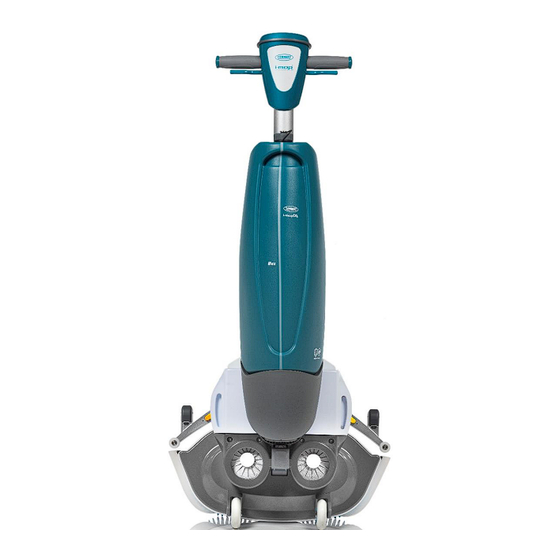
i-mop XL/XXL
Auto scrubber for hard floor surfaces
Service manual
Revision: 0.4 (11/2023)
Tennant N.V.
Industrielaan 6
5405 AB, Uden
P.O. Box 6
5400 AA, Uden
The Netherlands
Europe@tennantco.com
Advertisement
Table of Contents


Need help?
Do you have a question about the i-mop XL and is the answer not in the manual?
Questions and answers
I have a Tennant i-mop xl. I am looking for the part number for the squeegees and part number for the wheels.
The part number for the squeegee assembly for the Tennant I-Mop XL is 1232588. The context does not provide a specific part number for the wheels.
This answer is automatically generated