Advertisement
Table of Contents
- 1 Important Safety Instructions
- 2 Power Requirements
- 3 Input Controls
- 4 Signal Present Led
- 5 Compressor-Limiter Controls
- 6 Output Controls
- 7 Specifications
- 8 Input Impedance
- 9 Maximum Input
- 10 Frequency Response
- 11 Direct Input
- 12 Line Input
- 13 High Pass Filter
- 14 Time Constants
- 15 Product Warranty
- 16 Warranty Service
- Download this manual
Advertisement
Table of Contents

Related Manuals for Rupert Neve Designs SHELFORD CHANNEL


Summary of Contents for Rupert Neve Designs SHELFORD CHANNEL
- Page 1 SHELFORD CHANNEL Transformer Gain Mic Pre-amp Inductor EQ & Diode Bridge Compressor Operations Manual...
-
Page 2: Important Safety Instructions
CAUTION: Changes or modifications to this device not expressly 11. Only use attachments/accessories specified by the manufacturer. approved by Rupert Neve Designs LLC, could void the user's authority to 12. Use only with a cart, stand, tripod, bracket, or PORTABLE CART operate the equipment under FCC rules. - Page 3 Shelford Channel User Guide Thank you for your purchase of the Shelford Channel. Over fifty years in the making, the Shelford Channel is the definitive evolution of the original technologies in Rupert’s classic console modules like the 1073, 1064, 1081 & 2254, thoughtfully advanced and refined for the 21st century studio. The Shelford Channel is built around Rupert Neve’s first new transformer-gain, class-A...
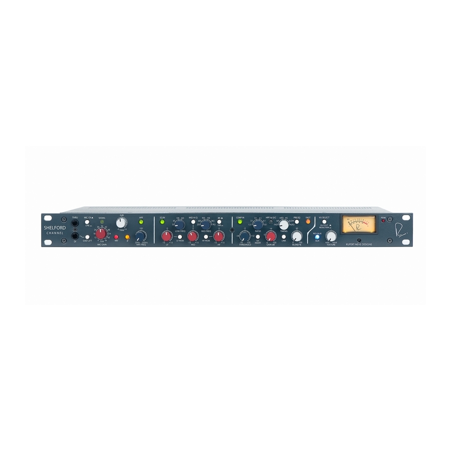
- Page 4 Shelford Channel: Front and Back Panels HPF Freq Selects frequency Low Freq where the 12 dB per octave Mid Freq high-pass filter 4 position switch 6 position select the begins to roll off selects corner or center frequency of low frequency signals.
- Page 5 RETURN COMPRESSOR Link Mic In Two TS jacks can be used to Transformer balanced input. Can handle join multiple Shelford Channel signals up to +8dBU. -6dB Line Output sidechain signals. 1= GND 2= Hot 3= Cold Transformer coupled, fully balanced and floating.
-
Page 6: Power Requirements
Rupert Neve Designs technical support. The Rupert Neve Designs Shelford Channel Overview The Rupert Neve Designs Shelford Channel is a full 19” rack width, 1.75” (1U) with standard rack mounting “ears.” Its construction incorporates a heavy and robust steel shell that provides total magnetic screening and exceptional mechanical stability. - Page 7 The Direct Input The Hi-Z front panel input uses the same discrete class-A FET and transformer topology as the Rupert Neve Designs RNDI, but it utilizes the new RN4012 input transformer directly coupled into the microphone preamp for gain. This design,...
- Page 8 Like the Inductor EQ and Transformer Gain microphone preamp, the Diode Bridge Compressor in the Shelford Channel is based on the same topologies found in Rupert’s vintage designs — such as the 2254 — but it expands on these early designs by incorporating full-wave rectification and a slew of new control features.
-
Page 9: Input Controls
The RATIO control has 6 steps between 1.5:1 to 8:1 to achieve a range of compression from subtle to extreme, and the THRESHOLD control has 31 detented steps between -25dBU and +20dBU to handle a wide variety of input levels. MAKE UP GAIN has 31 steps from -6dB to +20dB, and is affected by the blend setting (more on this later). - Page 10 This push button switch engages phantom power on the microphone input. Please remember to mute or turn down monitors and headphone sends on the channel that the Shelford Channel is plugged into before toggling “+48” (and be especially cautious if you use pre-fader aux sends for headphones).
- Page 11 EQ CONTROLS EQ In This switch engages all EQ frequency bands except the HPF. Adjusts up to 15 dB of boost or cut at the selected low frequencies. Cut can be used as a variable, and potentially more gentle alternative to using the HPF. Remember to reduce the signal level at the source to minimize the potential for clipping when any of the 3 bands are boosted significantly.
-
Page 12: Compressor-Limiter Controls
Mid Freq The MID FREQ rotary switch has 6 positions to select the center frequency of the mid band EQ stage. This circuit utilizes an inductor and capacitors to shape the EQ curve, the same way as Rupert Neve’s console designs of the 70’s. The chosen frequencies are 200 Hz, 400 Hz, 900 Hz, 1.8 kHz, 3.5 kHz and 7.5 kHz. - Page 13 work fine as well. A symptom of a balanced to unbalanced mismatch is that the “compression meter” will indicate a significant change in compression even when the EQ is set flat. Comp In The “COMP IN” button engages the compressor section. Threshold This control sets the level at which the compressor begins to attenuate, variable across a signal level range of -25 dB to +20 dB.
- Page 14 Timing This six-position controls adjusts the attack/release speed of the compressor. See the “Timing” section on page 18 for timing values. Link Links the side-chain control of multiple units for ganged operation, as would be used for stereo compression. Pre EQ In normal operation, the Compressor follows the EQ so that the Compressor can respond to significant tonal changes caused by the EQ.
-
Page 15: Output Controls
Red” accentuates the saturation in the high-mids and highs. Texture In the Shelford Channel, both “Silk” modes are modified and fine tuned by the “Texture” control. By manipulating the “Texture” control, the amount of “Silk” can be changed from essentially absent, to even greater levels than could be achieved with vintage products. -
Page 16: Maximum Input
Maximum Input +21.5dBu from 150Hz to 22kHz +8dBu 20Hz to 22kHz Gain Steps Position Gain (dB) Noise Un-weighted, 22Hz-22kHz, source impedance 150 Ohms balanced. Main Out @ unity gain -100.9dBu -6dB Out @ unity gain -106.6dBu +30dB gain (Main Out) -91.37dBu +66dB Gain (Main Out) -64.1dBu... -
Page 17: Line Input
Line Input Maximum Input Level +30.5dBu 20Hz to 30kHz Total Harmonic Distortion and Noise @ 1kHz, +20dBu output level, no load. Better than 0.002% @ 20Hz, +20dBu output level, no load. 0.05% Typical (2nd and 3rd harmonic) Noise @ Main Output -101.1dBu Un-weighted, 22Hz-22kHz, source impedance 40 Ohms balanced, no load. -
Page 18: Time Constants
Noise Un-weighted, 22Hz-22kHz, -92dBu Signal Present / Overload Indicator Signal Present Illuminates GREEN when input stage signal level reaches -20dBu Overload Illuminates RED when input stage signal level reaches -23dBu Diode Bridge Compressor Noise (BW 22Hz – 22kHz): 0 dB Makeup Gain: -84.5 dBu +20 dB Makeup Gain: -64.2 dBu Time Constants: Measurements taken represent full range achievable between 1.5:1 Ratio and 8:1... - Page 19 Low Frequency Peak Response Audio Precision 07/14/16 16:45:40 100k Sweep Trace Color Line Style Thick Data Axis Comment Cyan Solid Anlr.Level A Left 35Hz boost Green Solid Anlr.Level A Left 35Hz cut Solid Anlr.Level A Left 60Hz boost Magenta Solid Anlr.Level A Left 60Hz cut...
- Page 20 Mid-Band Low Q Frequency Response Audio Precision 07/01/16 13:31:05 +22.5 +17.5 +12.5 +7.5 +2.5 -2.5 -7.5 -12.5 -17.5 -22.5 100k 200k Sweep Trace Color Line Style Thick Data Axis Comment Cyan Solid Anlr.Level A Left 220Hz Green Solid Anlr.Level A Left 400Hz Solid...
- Page 21 Mid-Band High Q Frequency Response Mid-Band High Q Frequency Response Audio Precision 07/01/16 13:40:06 +22.5 +17.5 +12.5 +7.5 +2.5 -2.5 -7.5 -12.5 -17.5 -22.5 100k 200k Sweep Trace Color Line Style Thick Data Axis Comment Cyan Solid Anlr.Level A Left 220Hz Green Solid...
- Page 22 High Frequency Peak Audio Precision 07/14/16 17:05:45 +22.5 +17.5 +12.5 +7.5 +2.5 -2.5 -7.5 -12.5 -17.5 -22.5 100k 200k Sweep Trace Color Line Style Thick Data Axis Comment Cyan Solid Anlr.Level A Left 8kHz boost Green Solid Anlr.Level A Left 16kHz boost Solid Anlr.Level A...
- Page 23 HPF Frequency Response Audio Precision 07/01/16 09:22:01 100k 200k Sweep Trace Color Line Style Thick Data Axis Comment Cyan Solid Anlr.Level A Left Baseline Green Solid Anlr.Level A Left HPF @ 20Hz Magenta Solid Anlr.Level A Left HPF @ 250Hz 810-00042(ShelfordCh) HPF Freqeuncy Response Line Input to Main Output...
-
Page 24: Product Warranty
PRODUCT WARRANTY Rupert Neve Designs warrants this product to be free from defects in materials and workmanship for a period of one (1) year from date of purchase, and agrees to remedy any defect identified within such one year period by, at our option, repairing or replacing the product.
Need help?
Do you have a question about the SHELFORD CHANNEL and is the answer not in the manual?
Questions and answers