
Related Manuals for Clarke POWER IG1900


Summary of Contents for Clarke POWER IG1900
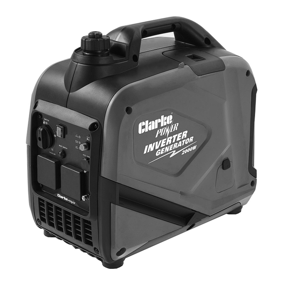
- Page 1 WARNING: Do not use the generator without reading this manual 2000W INVERTER GENERATOR MODEL NO: IG1900 PART NO: 8877117 OPERATION & MAINTENANCE INSTRUCTIONS ORIGINAL INSTRUCTIONS DL0524...
-
Page 2: Environmental Protection
INTRODUCTION Before you use this product, read this manual and follow the instructions carefully. In doing so you will ensure the safety of yourself and others around you, and you can also expect your purchase to give you a long and satisfactory service. -
Page 3: Specifications
SPECIFICATIONS Engine Engine Model KM148F Type Petrol Displacement (cc) 79.8 4800 Ignition type C.D.I Fuel tank capacity (L) Fuel Consumption at 3/4 Load (L/h) 1.13 Maximum run time at 3/4 load (h) Approx. 5 Engine oil capacity (L) 0.35 Emissions (g/kWh) CO, HC, NOx 379.68, 40.12, 1.93 Guaranteed sound power (LWA dB) Generator... -
Page 4: General Safety Rules
GENERAL SAFETY RULES WARNING: EXHAUST FUMES CAN BE EXTREMELY DANGEROUS IF INHALED WORK AREA 1. ALWAYS use in a well ventilated area. 2. ALWAYS position the exhaust outlet away from people. 3. Read these safety instructions before using the equipment. 4. - Page 5 3. NEVER use water or any other liquids to clean the generator. 4. Make sure you ground (earth) the generator (See pages 9-10). ADDITIONAL SAFETY RULES FOR GENERATORS 1. ALWAYS make sure the applied load does not exceed the generator rating.
-
Page 6: Safety Symbols
SAFETY SYMBOLS The following safety symbols are shown on the product or it’s packaging. Please read all of the safety and operating instructions carefully before using this product. Read instruction Hot surface - DO NOT manual before use. TOUCH Dangerous Voltage - Poisonous fumes - DO Risk of Electrocution. - Page 7 GENERATOR OVERVIEW - CONTROLS & OUTLETS NO DESCRIPTION NO DESCRIPTION ON/OFF/CHOKE Fuel Switch ON/OFF Switch Economy Control Switch 2 Pin 12V/8.3A DC Outlet Reset Button 2 x 3 Pin 13A 230V AC Outlets Oil Alarm, Overload & Output Earth Connection Point Indicator Lights Parts &...
- Page 8 GENERATOR OVERVIEW - GENERAL COMPONENTS NO DESCRIPTION NO DESCRIPTION Recoil Starter Spark Plug Cover Fuel Cap/Fuel Tank Vacuum Oil Filler Cap Cover Relief Valve Fuel Gauge Parts & Service: 020 8988 7400 / E-mail: Parts@clarkeinternational.com or Service@clarkeinternational.com...
-
Page 9: Unpacking And Assembly
UNPACKING AND ASSEMBLY Unpack your generator and check the following items are present. Should there be any missing or damaged during transit contact your CLARKE dealer. 1 x 2000 Watt Inverter Generator 1 x 12 Volt Crocodile Clip Lead Assembly... -
Page 10: Checking And Adding Engine Oil
Attach the cable to the generator at the earthing point (shown on the right). Connect the other end of the cable to a steel or copper earth rod, making sure you connect it in accordance with the installation instructions supplied with the rod. When pushing the rod into the ground the generator must not be running and it is suggested that the rod is pushed into the ground by at least... -
Page 11: Checking & Adding Fuel
• DO NOT fill above the max level mark. • We recommend the use of SAE10W-30 oil in this generator. (CLARKE part number 3050852) • DO NOT tilt the generator when adding engine oil. This could result in overfilling and damage to the engine. -
Page 12: Using Your Generator
2. Open the fuel filler cap located on top of the generator. 3. Slowly add fuel to the fuel tank. • DO NOT overfill the fuel tank. 4. Replace the fuel filler cap securely. USING YOUR GENERATOR STARTING THE ENGINE 1. - Page 13 (see item 4, page 6) may light up for a few seconds, this is normal. If the overload indicator is still lit after 5 seconds, stop the engine and contact your CLARKE dealer or the CLARKE Service Department.
-
Page 14: Economy Control Switch
ECONOMY CONTROL SWITCH ON (ECO MODE): Recommended to minimize fuel consumption and further reduce noise levels when no load is applied to the generator. Engine speed varies with the load. OFF (HIGH-SPEED MODE): The engine will run at the rated speed regardless of whether a load is connected or not. - Page 15 DC POWER 1. Set the economy control switch to ‘OFF’. 2. Start the generator. See pages 12-13. 3. Make sure the appliance is turned off before connecting it to the generator. 4. Lift the cover and connect the 12V appliance (max 8.3A) to the generator. DC POWER (TOPPING UP CAR BATTER- IES) WARNING: FOR YOUR SAFETY PERFORM THE FOLLOWING INSTRUCTIONS...
- Page 16 DC OVER LOAD PROTECTOR If the overload protector activates, wait for a few minutes and then press the reset switch shown on the right. INDICATOR LIGHTS OUTPUT The output indicator (Green) will remain on during normal operation. OVERLOAD The overload indicator (Red) will light up if there is an overload or a short circuit in the connected appliance.
- Page 17 SHUTTING DOWN THE GENERATOR To stop the generator simply set the engine switch to ‘OFF’. NOTE: Turn off any electric devices. NOTE: Set the economy control switch to the ‘0’ (OFF) position. 1. Disconnect any electric devices. 2. Turn the fuel switch to the “OFF”. 3.
-
Page 18: Maintenance
• DO NOT fill above the max level mark (0.35 litres) • We recommend the use of SAE10W-30 oil in this generator. (CLARKE part number 3050852) 5. Replace the oil filler cap and maintenance panel. ENVIRONMENTAL PROTECTION One of the most damaging sources of pollution is oil. DO NOT throw away used engine oil in with your domestic waste or down drains and sinks. - Page 19 3. Remove the air filter cover. 4. Remove the air filter element. 5. If the air filter is damaged contact the CLARKE spare parts department for a replacement. • If the filter is dirty, wash it in a solution of warm water and mild detergent and then rinse thoroughly.
- Page 20 CHANGING SPARK PLUG (EVERY 50 HOURS OF USE) CAUTION: ALLOW THE ENGINE TO COOL BEFORE REMOVING THE SPARK PLUG. 1. Remove the spark plug cover panel located on top of the generator. 2. Remove the spark plug cap from the spark plug. 3.
- Page 21 1. Remove the fuel tank cap. 2. Lift out the filter inside. 3. Clean the filter with solvent. If the filter is damaged, contact CLARKE Spare Parts department 020 8988 7400 for a replacement. 4. Replace the filter and fuel tank cap.
-
Page 22: Troubleshooting
Generator is not on level Move generator to a level surface surface to prevent low oil shutdown from triggering Engine needs Contact the CLARKE service maintenance department for more information Generator was tilted when Remove spark plug, turn engine adding oil or shipped side... - Page 23 Short circuit in one of the Try disconnecting any faulty or connected devices short circuited electrical loads If this does not solve your problem, please contact the CLARKE Service Department. Parts & Service: 020 8988 7400 / E-mail: Parts@clarkeinternational.com or Service@clarkeinternational.com...
- Page 24 DECLARATION OF CONFORMITY -UKCA Parts & Service: 020 8988 7400 / E-mail: Parts@clarkeinternational.com or Service@clarkeinternational.com...
-
Page 25: Declaration Of Conformity (Ce)
DECLARATION OF CONFORMITY -CE Parts & Service: 020 8988 7400 / E-mail: Parts@clarkeinternational.com or Service@clarkeinternational.com... - Page 26 EXPLODED DIAGRAM - ENGINE Parts & Service: 020 8988 7400 / E-mail: Parts@clarkeinternational.com or Service@clarkeinternational.com...
-
Page 27: Parts List - Engine
PARTS LIST - ENGINE Description Description Recoil Starting Assembly Valve Lifter Nut (M12 x 1.25) Push Rod Starting Pulley Piston Flywheel Circlip (Piston Pin) Rotor Piston Pin Stator Connecting Rod 35mm Flip-Flop Big End Air Filter Bolt Damping Base Crankshaft Bolt (M6 x 30) Oil Seal Recoil Starter Housing... - Page 28 Bolt Nut (M6 x 8) Exhaust Pipe Connector Valve Rocker Arm Waste Pipe Valve Rocker Arm Shaft Crankcase Cover Set Cylinder Head Cover Oil Level Gauge Cover Plate Exhaust Pipe Connector Oil Gauge Set Bolt Muffler Limit Plate Bolt (M6 x 12) Intake Gasket Air Duct Carburetor Insulation Board...
- Page 29 EXPLODED DIAGRAM - GENERATOR Parts & Service: 020 8988 7400 / E-mail: Parts@clarkeinternational.com or Service@clarkeinternational.com...
- Page 30 PARTS LIST - GENERATOR Description Description Rear Cover Left Cover Plate Screw (M5 x 16) Screw (ST3 x10) Bushing Handle Trim Cover Nut (M5) Corner Piece Cover (Right) Fuel Tank Starting Handle Rubber Gasket Corner Piece Cover (Left) Nozzle Soundproofing Cotton Fuel Pipe Baseplate Fuel Pipe...
- Page 31 Panel Cover Voltmeter Locating Pin Cover EU Socket Screw (M5 x 16) 3 in 1 Indicator Valve Cable Pressing Plate Switching Panel Earth Bolt Screw (M5 x 16) Right Handle Idling Switch Screw T Type Socket Gasket Socket (Connected to Grid) Right Cover Plate Parts &...
Need help?
Do you have a question about the POWER IG1900 and is the answer not in the manual?
Questions and answers