Advertisement
Quick Links
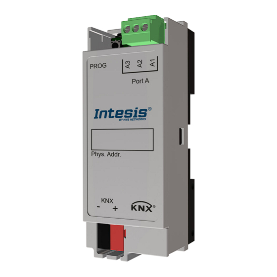
INKNXMBM1000200
Modbus RTU Client to KNX gateway
Order Code: INKNXMBM1000200
Installation Sheet v.1.0
HMS Industrial Networks S.L.U ©
SAFETY INSTRUCTIONS
WARNING
!
Follow these safety and installation instructions carefully.
Improper work may lead to serious harm to your health
and may seriously damage this Intesis gateway and/or
any other installation equipment.
Only accredited technical personnel, following all these safety
instructions and in accordance with the country's legislation for the
installation of electric equipment, are authorized to install this Intesis
gateway.
Install this gateway indoors, save from direct solar radiation, water,
high relative humidity, or dust.
Install this gateway in a restricted access location.
Disconnect any wire from its power supply before manipulating and
connecting it to this gateway.
Respect the expected polarity of power and communication cables
when connecting them to this gateway.
Supply the correct voltage to power this gateway. The admitted range
voltage is detailed in the electrical and mechanical features table
below.
CAUTION: Connect this gateway only to networks without routing to
the outside plant. All communication ports are considered for indoor
use only and can be connected to SELV circuits only.
This gateway has been designed for installation in a closed electric
cabinet. To avoid electrostatic discharge to the unit in environments
with static levels above 4 kV, take precautions if it is mounted in a
different enclosure than the one recommended. When handling the
gateway, take appropriate anti-static precautions.
Find these safety instructions in other languages at:
https://intesis.com/docs/manuals/v6-safety
CONFIGURATION
Use the official KNX software tool
To know more about the gateway's configuration and commissioning,
please refer to
the user
manual.
INSTALLATION
•
Mount the gateway in a DIN rail cabinet or a closed electrical
junction box. Please note that this gateway's profile (depth) may
be thinner than other devices on the DIN rail. Check the local
regulations since installing a blanking plate may be necessary to
cover the gateway and avoid any manipulation through the gap.
•
Disconnect the power supply of the KNX bus.
•
Connect the communication cables to the gateway. See details in
the Connections and Switches section.
•
Reconnect the power supply of the KNX bus.
•
Connect the EIA-485 device(s) to its power supply.
NOTE: Do not install the device in air-handling ducts.
Version.1.0
© HMS Industrial Networks S.L.U - All rights reserved
This information is subject to change without notice
ETS
to configure this gateway.
Owner's Record
Find the serial number on the silver label on the right side of the
gateway. We recommend you write it in the space below for sales
or technical assistance:
SN:
TECHNICAL SPECIFICATIONS
• Front side: PC (UL 94 V-0)
• Back side: PPO (UL 94 V-0)
• Net dimensions (dxwxh): 32x36x92 mm
Enclosure
Colors:
• Front side: light grey. RAL 7035
• Rear side: black
Mounting
DIN rail (35 mm; two modules)
Supplied through KNX bus. See KNX Port below.
Power
1 x KNX TP-1 Plug-in terminal block (2 poles)
• 1500VDC isolation from other ports
KNX Port
• KNX power consumption: 22mA
• Voltage rating: 30VDC
1 x Serial EIA-485 Plug-in screw terminal block (3
poles)
• A1: SNGD (Reference ground or shield)
Port A
• A2 (B-)
• A3 (A+)
2500VDC isolation from other ports
Push Button
Activates the gateway's programming mode
Operation
0°C to +60°C
Temperature
Operational
5 to 95%, no condensation
Humidity
DIP switch for serial EIA-485 configuration:
• Switch 1:
• ON: 120 Ω termination active
• OFF: 120 Ω termination inactive (Default)
SW1
• Switches 2 and 3:
• ON: Polarization active (Default)
• OFF: Polarization inactive
2 x Onboard LED indicators
• 1 x Power/Port A activity
LED Indicators
• 1 x KNX programming mode
URL
https://www.intesis.com
1 / 2
Advertisement

Related Manuals for HMS Networks Intesis INKNXMBM1000200


Summary of Contents for HMS Networks Intesis INKNXMBM1000200
- Page 1 Owner’s Record INKNXMBM1000200 Find the serial number on the silver label on the right side of the gateway. We recommend you write it in the space below for sales Modbus RTU Client to KNX gateway or technical assistance: Order Code: INKNXMBM1000200 Installation Sheet v.1.0 HMS Industrial Networks S.L.U ©...
- Page 2 CONNECTIONS AND SWITCHES Identifies the status of the 120 Ω terminal resistor functionality and bus polarization. The factory settings are: termination resistor disabled and line polarization enabled (See SW1 configuration details in the Technical Specifications table). Port A / EIA-485 Connect the EIA-485 bus to connectors A3 (A+), A2 (B-), and A1 (SNGD) of the gateway’s Port A as indicated in the connection diagram.
Need help?
Do you have a question about the Intesis INKNXMBM1000200 and is the answer not in the manual?
Questions and answers