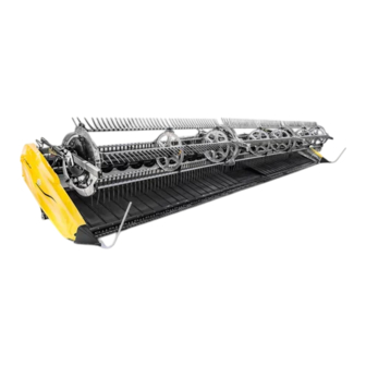
MacDon FlexDraper FD2 Series Manual
Header/float module
Hide thumbs
Also See for FlexDraper FD2 Series:
- Operator's manual (566 pages) ,
- Manual (560 pages) ,
- Installation instructions manual (60 pages)
Advertisement
Quick Links
Recommended Fluids and Lubricants
Ensure your machine operates at top efficiency by using clean fluids and lubricants only.
Use clean containers to handle all fluids and lubricants.
Store fluids and lubricants in an area protected from dust, moisture, and other contaminants.
Lubricant
Specification
High temperature extreme
pressure (EP) performance
grease with 1% max
Molybdenum Disulphide
(NLGI Grade 2) lithium base
Grease
SAE multi-purpose
High temperature extreme
pressure (EP) performance
grease with 10% max
Molybdenum Disulphide
(NLGI Grade 2) lithium base
Gear Lubricant SAE 85W-140
API service class GL-5
Single grade trans-hydraulic oil
Recommended viscosity:
60.1 cST @ 40°C
9.5 cST @ 100°C
Hydraulic Oil
Lubricant trans / hydraulic oil
Recommended brands:
Petro-Canada Duratran
John Deere Hy-Gard J20C
Case Hy-Tran Ultraction
AGCO Power Fluid 821 XL
Break-In Inspections
To help avoid major component service or replacement, perform break-in inspections on your machine for the first 50 hours of
operation. Refer to your operator's manual for complete break-in inspection and adjustment procedures.
Interval
First 5 Minutes
Check hydraulic oil level in reservoir (check after first run-up and after the hydraulic hoses have filled with oil).
5 Hours
Check for loose hardware and tighten to required torque.
Check auger drive chain tension.
10 Hours
Check knife drive box mounting bolts.
Grease feed draper drive roller and idler roller bearings.
Change float module gearbox oil.
Change float module hydraulic oil filter.
50 Hours
Change knife drive box lubricant.
Check gearbox chain tension.
Ongoing Maintenance Intervals
Refer to the operator's manual for a comprehensive maintenance schedule and record. Log hours of operation, use the maintenance
record, and keep copies of your maintenance records.
Following the maintenance schedule will increase your machine's life.
Description
Use
Capacities
As required unless
otherwise specified
Driveline slip-joints
Knife drive box
1.5 liters (1.3 quarts)
Main gearbox
2.75 liters (2.9 quarts)
Completion gearbox
2.25 liters (2.4 quarts)
Header drive systems
95 liters
reservoir
(25.1 US gallons)
Item
Subject to change without notice
Follow these five steps in order to set the header float and wing balance:
NOTE:
Read your operator's manual and complete all the setup tasks before setting the header float.
—
a.
Park combine on a level surface, and ensure the combine feeder house
is level. Use bubble level on float module.
—
b. Adjust header so cutterbar is 250 mm (10 in.) (A) off the ground.
c.
Set the header angle hydraulic cylinder to D on indicator (B).
d. Set the reel fore-aft to 6 on reel arm fore-aft indicator (C).
e. Lower the reel completely, shut down the combine, and remove key
from the combine ignition.
f.
Remove linkage cover (A).
g.
Place both left and right wing lock spring handle (B) in the locked
(upper) position. You should hear the lock engaged. If not, move the
wings up and down, so that the lock engages.
h. Place both left and right header float locks in unlocked (lowered)
position (A).
i.
Set stabilizer/transport wheels or contour wheels (if equipped) to
upper most position.
SETTING HEADER FLOAT AND WING BALANCE
Step 1: Preadjustments
Figure 1: Header – Side View
Figure 2: Wing Lock Spring Handle in Locked Position – Left
Side Shown
Figure 3: Float Unlocked – Left Side Shown
Advertisement

Subscribe to Our Youtube Channel
Summary of Contents for MacDon FlexDraper FD2 Series
- Page 1 Recommended Fluids and Lubricants Ensure your machine operates at top efficiency by using clean fluids and lubricants only. Use clean containers to handle all fluids and lubricants. Store fluids and lubricants in an area protected from dust, moisture, and other contaminants. SETTING HEADER FLOAT AND WING BALANCE Lubricant Specification...
- Page 2 If the lock does not engage, move the wing up and down available adjustments, an optional heavy duty spring is available. See with tool until it locks. your MacDon Dealer or refer to the parts catalog for ordering information. Detach the flex checker cable from the flex checker lock.


Need help?
Do you have a question about the FlexDraper FD2 Series and is the answer not in the manual?
Questions and answers