MacDon FM200 Installation Instructions Manual
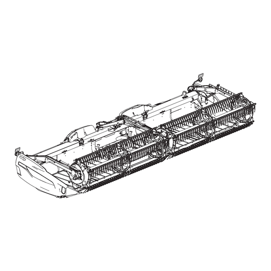
Float module
Hide thumbs
Also See for FM200:
- Operator's manual (566 pages) ,
- Manual (560 pages) ,
- Quick start manual (2 pages)

Related Manuals for MacDon FM200


Summary of Contents for MacDon FM200
- Page 1 FM200 Float Module Feed Auger Hub Service Kit (MD #337804) Installation Instructions 215448 Revision A Original Instruction The Harvesting Specialists.
- Page 2 © 2020 MacDon Industries, Ltd. The information in this publication is based on the information available and in effect at the time of printing. MacDon Industries, Ltd. makes no representation or warranty of any kind, whether expressed or implied, with respect to the...
- Page 3 • Unless otherwise noted, use the standard torque values provided in the header operator’s manual and technical manual. NOTE: Keep your MacDon publications up-to-date. The most current version of this instruction can be downloaded from our Dealer-only site (https://portal.macdon.com) (login required). NOTE: This document is currently available in English only.
-
Page 5: Table Of Contents
TABLE OF CONTENTS Introduction ..............................i Chapter 1: Safety ............................1 1.1 Signal Words ............................1 1.2 General Safety ............................2 Chapter 2: Parts List............................ 5 Chapter 3: Installation Instructions ......................7 3.1 Feed Auger Left Side Removal........................7 3.2 Feed Auger Left Side Hub Replace ......................11 3.3 Feed Auger Left Side Install ........................ -
Page 7: Chapter 1: Safety
Chapter 1: Safety Understanding and following safety procedures consistently will help to ensure the safety of machine operators and bystanders. 1.1 Signal Words Three signal words, DANGER, WARNING, and CAUTION, are used to alert you to hazardous situations. Two signal words, IMPORTANT and NOTE, identify non-safety related information. -
Page 8: General Safety
SAFETY 1.2 General Safety Protect yourself when assembling, operating, and servicing machinery. CAUTION The following general farm safety precautions should be part of your operating procedure for all types of machinery. Wear all protective clothing and personal safety devices that could be necessary for the job at hand. - Page 9 SAFETY • Wear close-fitting clothing and cover long hair. NEVER wear dangling items such as scarves or bracelets. • Keep all shields in place. NEVER alter or remove safety equipment. Make sure driveline guards can rotate independently of shaft and can telescope freely. •...
-
Page 11: Chapter 2: Parts List
Chapter 2: Parts List A parts list is provided in this instruction so that you can confirm that you have received all required parts before you begin installation. Part Number Description Quantity ASSEMBLY – LH HUB WITH BEARING WASHER – FLAT 123406 NSS –... -
Page 13: Chapter 3: Installation Instructions
Chapter 3: Installation Instructions To install the kit, follow this procedure. 3.1 Feed Auger Left Side Removal DANGER To avoid bodily injury or death from unexpected start-up or fall of raised machine, always stop engine, remove key, and engage safety props before going under machine for any reason. 1. - Page 14 INSTALLATION INSTRUCTIONS 9. Loosen two bolts (A) and remove bumper (B). Figure 3.3: Auger Bumper – Left 10. On the left side of the auger, remove bolts (E) and remove cover retainer (F). 11. Remove four bolts (A) and inspection panel (B). 12.
- Page 15 INSTALLATION INSTRUCTIONS 15. Loosen jam nut (C) and turn thumbscrew (D) counterclockwise to release the bolt holding sprocket (B) and preventing it from being raised up to release chain tension. IMPORTANT: Do NOT loosen thin nut (E) on the inboard side of the idler sprocket spindle.
- Page 16 INSTALLATION INSTRUCTIONS NOTE: Once the drum starts sliding to the right, drive sprocket (A) will fall off the shaft. Figure 3.8: Auger Drive – View from Behind 215448 Revision A...
-
Page 17: Feed Auger Left Side Hub Replace
INSTALLATION INSTRUCTIONS 3.2 Feed Auger Left Side Hub Replace 1. Remove outermost left access cover (A) by removing two bolts (B). Figure 3.9: Drum Access Cover 2. Inside the drum, place a block (B) under finger shaft (A) to support it when the hub is removed. Figure 3.10: Left Pivot Block –... - Page 18 INSTALLATION INSTRUCTIONS 5. Remove nut (A) and finger shaft crank arm (B). 6. Remove woodruff key (C) from shaft. Figure 3.12: Left Assembly 7. Slide hub (A) off of shaft (B). 8. Retrieve washer (MD #123406) from the shipping bag. 9.
- Page 19 INSTALLATION INSTRUCTIONS 10. Remove six nuts (B) and bolts (A), hub (C), and sprocket (D). 11. Retrieve new hub with bearing from the shipping bag. Figure 3.14: Left Assembly 12. Install hub (C) on top of sprocket (D). 13. Install six bolts (A) and six nuts (B). Figure 3.15: Left Hub Assembly 14.
- Page 20 INSTALLATION INSTRUCTIONS 17. Slide left feed auger assembly (C) into the drum. Align pivot pin (C) with the bushing in pivot block (A). 18. Remove wooden block (B) supporting finger shaft (D). Figure 3.17: Left Pivot Block 19. Secure hub (A) to the drum with six bolts and washers (A). Figure 3.18: Left Assembly 20.
-
Page 21: Feed Auger Left Side Install
INSTALLATION INSTRUCTIONS 3.3 Feed Auger Left Side Install 1. Place drive chain (B) over the sprocket on the drive side of auger (A). Figure 3.20: Auger Drive 2. Place drive sprocket (B) into chain (A) and align the sprocket onto the shaft. NOTE: Shoulder of drive sprocket (B) should face the auger. - Page 22 INSTALLATION INSTRUCTIONS 5. Align the drive housing from the auger mount bracket. Install two bolts and nuts (A). Figure 3.23: Auger Support – Left Side 6. Rotate the auger in reverse to take up the slack in the lower strand of the chain. IMPORTANT: Do NOT loosen thin nut (C) on the inboard side of the idler sprocket spindle.
- Page 23 INSTALLATION INSTRUCTIONS 10. If installed, install bumper (B) and tighten two bolts (A) on the left side of the auger. Install bumper (B) and tighten two bolts (A) on the left side of the auger. Figure 3.26: Auger Drive – Left 11.
- Page 24 INSTALLATION INSTRUCTIONS 15. Remove ratchet strap (A) from around the drum and the float module frame. Figure 3.28: Float Module View From the Front 16. Remove wooden blocks (A) from the top of the feed draper. Figure 3.29: Blocks under the Auger 215448 Revision A...
- Page 26 MacDon Industries Ltd. MacDon Brasil Agribusiness Ltda. 680 Moray Street Rua Grã Nicco, 113, Sala 404, B. 04 Winnipeg, Manitoba Mossunguê, Curitiba, Paraná Canada R3J 3S3 CEP 81200-200 Brasil t. (204) 885 5590 f. (204) 832 7749 t. +55 41 2101 1713 f. +55 41 2101 1699 MacDon, Inc.
Need help?
Do you have a question about the FM200 and is the answer not in the manual?
Questions and answers