Table of Contents
Advertisement
Quick Links
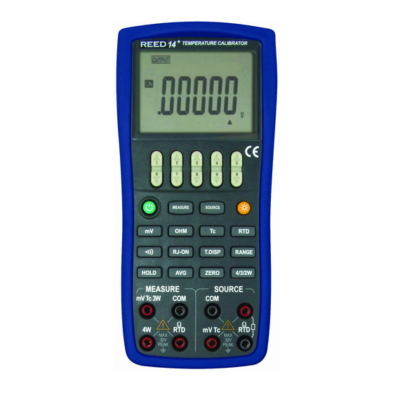
Temperature Calibrator
1 Introduction
This temperature calibrator (the calibrator in the following) is a handheld, battery-operated instrument that
measures and sources electrical and physical parameters.
Features:
Measure: DC-voltage, ohm, Tc, RTD, continuity;
Source: DC-voltage, ohm, Tc, RTD;
Others features:
2-wire,3-wire,4-wire connection method for ohm and RTD measurement.
Big LCD can display the TC/RTD measurement value and voltage/resistance corresponding
simultaneously.
TC measurement/source terminals and built-in lead connector of same temperature (RJ compensation
with auto-reference joint point)
Room temperature monitoring under any operation
Measurement wave-filter function
Measurement manual-holding function
2 Contact Us
To purchase parts, obtain operation help or address of the vendor or service center nearest to you, please call
1
Advertisement
Table of Contents

Related Manuals for REED VC14+


Summary of Contents for REED VC14+
- Page 1 Temperature Calibrator 1 Introduction This temperature calibrator (the calibrator in the following) is a handheld, battery-operated instrument that measures and sources electrical and physical parameters. Features: Measure: DC-voltage, ohm, Tc, RTD, continuity; Source: DC-voltage, ohm, Tc, RTD; Others features: 2-wire,3-wire,4-wire connection method for ohm and RTD measurement. ...
-
Page 2: Standard Accessories
us or visit our web (see the bottom page of the Manual). Standard Accessories Make sure that the package contains all the accessories listed below. And if you find they are damaged or any of them is missing, please contact the vendor from which you purchased the product as soon as possible. Refer to the replacing part list in 15.3 in the Manual if you want to order the replacing parts. - Page 3 Table 1 Explanations of International Electrical Symbols WARNING EARTH GROUND INFORMATION Warning To avoid possible electric shock or personal injury: Do not apply more than the rated voltage, as marked on the calibrator, between terminals or between any terminal and earth ground; Before use, verify the meter’s operation by measuring a known voltage;...
- Page 4 Do not operate this instrument in areas where inflammable or explosive gases or vapor exists. It is extremely hazardous to use the instrument under such environments; Do not operate the meter around explosive gas, vapor, or dust; Use only type 4 AAA batteries, properly installed in the meter case, to power the meter; ...
- Page 5 5 Familiar With the Calibrator Figure 1 Entire Graph...
- Page 6 5.1 Measurement/ Source Terminals Figure 2 shows the measurement /source terminals of the calibrator. Table 2 explains their use.
- Page 7 Figure 2 Measurement/ Source Terminals Figure 3 keys Table 2 Measurement/ Source Terminals Terminal Function 4W terminals : measurement terminal of the 4W OHM、 ① Measurement Signals(+):OHM、RTD ② Measurement Signals(+):DCV、TC 3W Terminal:measurement terminal of the 3W OHM、 ③ All the common (return ) (-)terminals of measurement ④...
- Page 8 Source Signals:(+)DCV、TC ⑤ Source Signals:(-)OHM、RTD ⑥ All the common (return ) (-)terminals of source function ⑦ Source Signal:(+)OHM、RTD ⑧ 5.2 Keys Figure 3 shows keys of the calibrator. Table 3 explains their use. Table 3 Functions of the keys Name Function Source value set key Increment of source set point...
- Page 9 OHM Key Select measurement/source OHM function Tc Key Select measurement/source Tc function Select measurement continuity function RANGE Key Select measurement/source range RJ-ON Key In TC measurement /source function, turn on or off the RJ compensation function. T.DISP Key In TC/RTD measurement /source function, pressing the key, convert the assistance display between room temperature or mV/Ωvalue;...
- Page 10 5.3 Display Screen Figure 4 shows a typical display screen. a:Measurement b:Source c:Measurement/Source resistance d:Battery level indicator e:Measurement/ Source function on f: Measurement/ Source DC-voltage function g:Measurement/ Source Tc function h:Measurement/ Source RTD function i:Beeper of measurement continuity j:Display –hold for measured value k:Average value for measurement Figure 4 typical LCD display l:4/3/2W for Measurement ohm/RTD function...
- Page 11 s:Unit of room temperature/ Tc(mV) or RTD(Ω) Unit of subsection value 6 Before starting source/measurement Operating Precautions Precautions for Safe Use of the Instrument When using the instrument for the first time, be sure to read the instructions given in Section Four ...
-
Page 12: Environmental Requirements
all lead cables from the instrument. Use a dedicated carry case when transporting the instrument. Do not bring any electrified object close to the input terminals, since the internal circuit may be destroyed. Do not apply any volatile chemical to the instrument’s case or operation panel. Do not leave the ... - Page 13 Exposed to frequent mechanical vibration. Close to any noise source, such as high-voltage equipment or motive power sources. Close to any source of intensive electric or electromagnetic fields. Exposed to large amounts of greasy fumes, hot steam, dust or corrosive gases. ...
- Page 14 as well as from the instrument itself. Caution To avoid the risk of fluid leakage or battery explosion, install batteries with their positive and negative electrodes correctly positioned. Do not short-circuit the batteries. Do not disassemble or heat the batteries or throw them into fire. ...
- Page 15 The battery level is below 50% full: The battery level is below 25% full: Low battery: The dictation flashes in sequence when getting charged. Note that the battery replacement indicator is driven by directly measuring the battery voltage when the calibrator is in actual operation.
-
Page 16: Automatic Power Off
Charger connection jack. Plug out the Charger from the Charger connection jack of the calibrator when discharging. Do not charge the calibrator without any battery in. Turning On the Power Pressing the Power key once when the power is off turns on the calibrator. Pressing the Power key for 2 seconds turns off the calibrator. - Page 17 To avoid electrical shock, do not apply more than the rated voltage, as marked on the calibrator, between terminals or between any terminal and earth ground. Always use the calibrator in locations with a voltage to ground below 30 Vpk. Caution The instrument has been calibrated without taking into account a voltage drop due to the resistance ...
- Page 18 Step 2: Connect the other ends of the cables to the input of equipment under test while making sure the polarities are correct. Figure 6 Sourcing Resistances and RTD 7.2 Sourcing DC Voltage Step 1: Using the〔mV〕key to select DC voltage source function, select the desired range from 100mV, 1000mV by pressing the〔RANG〕key.
- Page 19 employ this method of measurement. The allowable range of the resistance measuring current I that the calibrator receives from a resistance measuring device under calibration is rated as 0.1 mA to 3 mA. To ensure accuracy, the resistance measuring current I from the device under calibration shall be strictly confined within the range. For further details, see Chapter 17, “Specification”.
- Page 20 7.4 Simulate Sourcing TC The calibrator is designed with an internal temperature sensor. To calibrate a device with built-in reference junction temperature compensation by sourcing a thermoelectromotive force with the calibrator without using non-external 0℃ reference junction compensation means, use the RJ sensor function. Select simulate TC source function, in which RJ senor goes on work automatically.
- Page 21 Tips: The temperature unit is defaulted as ℃.To convert into ℉,see Chapter 10 “Factory Default” . 7.4.1 Temperature Monitor Function The calibrator offers a temperature monitor function, which is convenient for the user to observe the voltage value sourced between the output terminals in TC source function. In TC source function, the assistance district of the LCD shows the voltage value sourced between the output terminals,(varies responding to the changes of the reference junction compensation).
- Page 22 resistance signal. Step 1: Using the〔RTD〕key, select RTD function. Using the〔RANGE〕key, select a desired RTD range from PT100, PT200, PT500, PT1000, Cu10, Cu50. The selected function and the default range source value and unit shall be shown in the main district of the LCD and the type of the RTD shall be shown in middle port of the LCD.
- Page 23 8 Measurement From the calibrator, you can measure a DC voltage, resistance, thermocouple, RTD and continuity. Warning In an application where the calibrator is used together with the supplied lead cables for measurement, the allowable voltage to ground of the input terminals is 30 Vpeak maximum.
- Page 24 the “COM” input terminal and the red lead cable to the ”mVTc3W” input terminal. Step 2: Connect the other end of the cable to the measuring terminals of equipment under test while making sure the polarities are correct. Figure 7 Measuring DC voltage For thermocouple signal (Figure 8) Step 1: Connect the thermocouple convertor to the input terminals.
- Page 25 Two wire connection method for continuity, ohm/RTD signal (Figure 9) Step 1: Connect one black lead cable for measurement to the “COM” input terminal and Connect the red lead cable to the ” ΩRTD” input terminal. Step 2: Connect the two clips of the cables to the measuring terminals of equipment under test while making sure the polarities are correct.
-
Page 26: Measuring Dc Voltage
Four wire connection method for ohm/RTD signal (Figure Step 1: Connect one black lead cable for measurement to the “COM” input terminal and another black lead to the “mVTc3W” terminal. Connect one red lead cable to the ” ΩRTD” input terminal and another red lead to “4W”... -
Page 27: Measuring Resistance
Step 3: Connect the lead cables for measurement to the measuring terminals of the measuring instrument under test. Step 4: Using the〔RANGE〕key, select a desired range from 50mV, 500mV. The selected function and the measured value and unit shall be shown in the main districts part of the LCD. 8.3 Measuring Resistance Step 1: Make sure the lead cables for measurement are not connected to the measuring instrument under test. - Page 28 and the measured value and unit shall be shown in the main districts part of the LCD. Tips: If there has been a sudden change in the operating ambient temperature of the calibrator, wait until the built-in reference junction compensation stabilizes. Avoid using the calibrator in locations exposed to wind from such apparatus as an airconditioner.
-
Page 29: Measuring Continuity
under test as shown in Figure 9, Figure 10 or Figure 11. Step 4: Using the measurement〔RANGE〕key, select a desired range from PT100,PT200,PT500,PT1000,Cu10,C50.The selected function and the default measured value and unit shall be shown in the main districts part of the LCD. Tips: The calibrator offers the 2-wire/3-wire/4-wire connection method when measuring ohm/RTD. -
Page 30: Factory Default
LCD shows the “AVG” symbol. Repressing the〔AVG〕key cancels the calculation and the “AVG” symbol disappears. 8.8 Measured Value holding function Apart from the continuity measurement functions, the reading-hold function can also be used to preserve the current measured value on the main districts part of LCD, which consequently doesn’t refresh the measured value. -
Page 31: Setting Backlight Time
Step 2: Set the time within 0-60 minute range by using the second pair of 〔〕 / 〔 〕 counting from right to left. Each press of the 〔〕 / 〔 〕 key causes 10 -minute increments or 10- minute decrement with constant setting. Constant press of the key causes increments or decrement of the value in sequence. -
Page 32: Setting Frequency
Step 1: Pressing the〔MEASURE〕key ,LCD displays “TEM.U” symbol on the upper part, indicating temperature unit setting mode. Step 2: Shifting between the ℃ and ℉ by using the right pair of 〔〕/〔〕. Step 3: Pressing the〔SOURCE〕key, LCD displays “SAVE” symbol on the upper part for 1s. 10.4 Setting frequency Step 1: Pressing the〔MEASURE〕key ,LCD displays “FRSET”... - Page 33 BL.OFF: 10sec. TMP.U: ℃. FRSET: 50 Hz. CMSET: PCM Tips: Any change of setting to the above-mentioned function, press the 〔SOURCE〕 key to save the value. Any press of the〔SOURCE〕key saves the nearest setting value. 11 Adjusting Measurement Functions Environmental Requirements Ambient temperature: 23 +2℃...
- Page 34 Range Adjustment Point Remarks DCV_50mV 50mV DCV_500mV 500mV OHM_500Ω 0Ω 500Ω 2W connection OHM_5KΩ 0Ω 5KΩ 2W connection ﹡Applying reference input signals from the calibration standard as listed in the above table. Tips: You can also select only the range in need of readjustment to adjust it separately. ...
- Page 35 11.1 Adjusting all ranges of the DC Voltage NORMAL SCOPE MEASURE SOURCE mV Tc TRIG PEAK PEAK standard source ( 5520A ) Figure 12 Calibrating DC voltage Step 1: Make sure the lead cables for measurement are not connected to the measuring instrument under test.
- Page 36 for 2 seconds. Step 7: Pressing the〔HOLD〕key exits the CAL mode. Step 8: By repeating from step 4 to step 7 until all ranges have been adjusted. Tips: Adjustment to the DC voltage of 50mV range calibrates the TC temperature measurement range at the ...
- Page 37 Step 2: Using the〔OHM〕key, select ohm adjust function. Step 3: Connect the lead cables to the output terminals of the standard source as shown in Figure 13.(The 2 wire compensation of 5520A must be open ) Step 4: Pressing the〔RANGE〕key selects the range. Step 5: Pressing the〔HOLD〕key enters the ohm CAL mode.
- Page 38 Environmental Requirements Ambient temperature: 23 +2℃ Relative humidity: 35% to 75% RH Warm-up: Before using, warm up the calibrator for the period of time specified. Set the meter into the standard environment for 24 hours, and then turn on the power. Change the set into ...
- Page 39 When adjusting resistance source, the exciting current is (+) for adjustment point ‘’0’’ and ‘’F’’, and is (-) for adjustment point “–0” and “–F”. Turn on the meter; press the〔SOURCE〕key while simultaneously holding down the (MEASURE)key enters the source calibration state. LCD shows “CA-0” symbol on the assistance districts part, the present calibrating point on the main districts part and the high 5 digits of the responding value and its unit.
- Page 40 Step 2: Pressing the〔RANGE〕key selects the right range. Step 3: The LCD shows “CA-0” or “CA-F”symbol on the associate districts part and the calibrator is ready for the zero-point or F-point adjustment of source functions. The LCD shows the highest five digits and its unit in the main districts part and the lowest digit of the calibrated sourced value in the right of the assistance districts part respectively.
- Page 41 12.2 Adjusting Resistance Source digital meter KEITHLEY2000 ) NORMAL SCOPE MEASURE SOURCE mV Tc TRIG PEAK PEAK standard source (5520A) Figure 15 Adjusting resistance source Step 1: Using the〔OHM〕key, select resistance function. Connect the lead cables for measurement to the standard digital meter as shown in Figure15.
- Page 42 the reading so that it matches the measured CAL adjustment setpoint. In the CAL mode, the right pair of〔〕 /〔〕keys are used to increase or decrease the least-significant digit, (the digit in the right of the assistance districts LCD part). Step 5: Press the〔ZERO〕key to save the CAL adjustment reading.
- Page 43 13 Replacing Batteries or fuse: Warning To avoid possible electric shock, remove the test leads from the calibrator before open the battery door. And make sure the battery door is tightly closed before turning on the calibrator. Caution To avoid possible linkage of the liquid and explosion ...
-
Page 44: How To Use The Charger
Step 4:Reinstall and tighten the battery door, put on the protector before using the meter. 14 How to use the charger Warning The charger could be used only to specified product. Make sure the voltage of the AC power is same with the given voltage of the charger before connecting ... -
Page 45: Replacement Of Parts
Warning To avoid electrical shock or damaging the meter, serve the meter only by the replacement parts specified and never get water inside the case. Caution To avoid damaging the plastic lens and case, do not use solvents or abrasive cleansers. Clean the Calibrator with a soft cloth dampened with water or water and mild soap. - Page 46 Figure 17. Replacing part...
- Page 47 Table 6. Replacing parts Item Instruction Quantity Item Instruction Quantity Top panel Spring A plastic lens Spring B Rubber Key Spring C Terminal Wrapper AAA Alkaline battery Terminal Gasket Tilt-stand LCD Frame Screw M3*16 Battery Door Backlight Panel Plastic Screw Conductive Rubber Sponge:...
- Page 48 For more information about the options (see Figure 18) and its price, please contact the representative of the company. Table 7 Options No. Name of the Options Mode CALCT Temperature A000019 Probe TC Plug R/S/K/E/J/T /N/B/L/U Thermocouple Convertor TTK07210 Test Hoop TP907110 CA Charger A000020...
- Page 49 Connect the temperature probe with the instrument before power on the instrument. “ERR.MD” will be displayed on the display of the instrument if the connection failed. There will be no other displays if the connection succeeds, then the temperature probe will be work normally.
-
Page 50: Specifications
Step 4: Connect with the power supply, begin charge. Note: Power off the instrument when charging The charge lamp lighted when charging; the charge lamp dark when charge full; the charge lamp flicker when nonloaded. About the specifications and requires of the AC charger refer to the “user manual for calibrator options”. ... - Page 51 These specifications assume: A 1-year calibration cycle An operating temperature of 18℃ to 28℃ Relative humidity of 35% to 70% (non_condensing) Accuracy is expressed as ± (percentage of reading + percentage of range). F Function Referen Range Resol Accuracy Remark...
- Page 52 -100.0~1372.0C -100.0~0.0℃ : 1.2℃ error internal 0.1C 0.0~1372.0℃ : 0.8℃ temperature compensation caused by a sensor; -50.0C~850.0C -50.0℃~0.0℃ : 0.9℃ 0.0~850.0℃: 1.5℃ -60.0C~1120.0C -60.0~0.0℃ : 1.0℃ 0.0~1120.0℃ : 0.7℃ -100.0C~400.0C -100.0~0.0℃ : 1.0℃ 0.0~400.0℃ : 0.7℃ -200.0~1300.0C -200.0~0.0℃ : 1.5℃ 0.0~1300.0℃...
- Page 53 Pt100 -200.0C~800.0C -200.0 C ~ 0.0 C By using temperature scale 0.1C 0.5C ITS-90. 0.0 C ~ 400.0 C Does include lead 0.7C resistance. Assuming all three 400.0 C ~ 800.0 C RTD leads are matched for 3-w input.
- Page 54 CONT. 500Ω ≤50Ω sound 0.01Ω Excitation current Approximately :1mA Other feature: Rate: 2 Readings per Second about Normal Mode Rejection Ratio (NMRR) ≥60dB (at 50Hz or 60Hz) Common Mode Rejection Ratio (CMRR) ≥120dB (at 50Hz or 60Hz) Temperature Coefficient: 0.1 times the applicable accuracy specification per degree C for 5℃ to 18℃ ...
- Page 55 Function Reference Range Resoluti Accuracy Remark DC voltage 100mV -10.000mV ~ 1μV 0.02+0.01 Maximum output current: 0. 5mA 110.000mV 1000mV -100mV 10μV 0.02+0.01 Maximum output current: 2mA ~ 1100mV Resistance 400Ω 0.00Ω 0.01Ω 0.02+0.02 Excitation current: ± 0.5–3 mA; ~ 400.00Ω...
- Page 56 -200.0C~1000.0C -200.0~-100.0 : 0.6℃ -100.0~600.0℃:0.5℃ 600.0~1000.0℃: 0.4℃ -200.0C~1200.0C -200.0~-100.0 : 0.6℃ -100.0~800.0℃:0.5℃ 800.0~1200.0℃: 0.7℃ -250.0C~400.0C -250.0~400.0℃: 0.6℃ -200.0C~1300.0C -200.0~-100.0℃:1.0℃ -100.0~900.0℃: 0.7℃ 9000~1300.0℃: 0.8℃ 1C 600C~1820C 600~800℃ : 1.5℃ 800~1820℃: 1.1℃ -200.0 C ~ 0.1C -200.0~0℃ : 0.7℃ 0~900.0℃:0.5℃ 900.0C -200.0 ...
- Page 57 for Pt100, Cu10, Cu50 add 0.5C Pt200 -200.0C~630 -200.0~100.0℃: 0.8℃ when excitation current is .0C 100.0~300.0℃ : 0.9℃ ±0.1mA-0.5mA; 300.0~630.0℃ : 1.0℃ Excitation current: ±0.05mA ~ Pt500 -200.0 C ~ -200.0~100.0℃: 0.4℃ ±0.3mA PT200, PT500, 630.0C 1000.0~300.0℃ :0.5℃ PT1000; 300.0~630.0℃...
- Page 58 -20℃-100℃. 18 Points for Attention to Use of Operation Instruction The present operation instruction is subject to change without notice. The content of the operation instruction is regarded as correct. Whenever any user finds its mistakes, omission, etc, he or she is requested to contact the manufacturer. The present manufacturer is not liable for any accident and hazard arising from any misoperation.
Need help?
Do you have a question about the VC14+ and is the answer not in the manual?
Questions and answers