Table of Contents
Advertisement
Quick Links
Advertisement
Table of Contents
Troubleshooting

Related Manuals for Daikin ERA100A7V1B


Summary of Contents for Daikin ERA100A7V1B
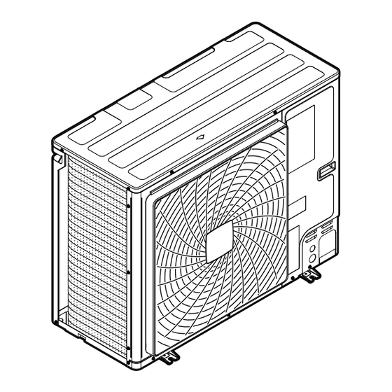
- Page 1 Installation and operation manual Inverter outdoor unit for AHU option kit and aircurtains ERA100A7V1B ERA125A7V1B ERA140A7V1B ERA100A7Y1B Installation and operation manual ERA125A7Y1B English Inverter outdoor unit for AHU option kit and aircurtains ERA140A7Y1B...
- Page 2 [mm] — ≥100 A, B, C — ≥100 ≥100 ≥100 B, E — ≥100 ≥1000 ≤500 A, B, C, E — ≥150 ≥150 ≥150 ≥1000 ≤500 — ≥500 D, E — ≥500 ≥1000 ≤500 >H B, D ≥100 ≥500 ≤H ≥100 ≥500 B, D, E...
- Page 3 All other floors m [kg] Lowest underground floor 2.2 m 2.2 m 1.8 m 1.8 m 25 30 35 40 45 50 55 60 70 75 80 85 90 95 100 25 30 35 40 45 50 55 60 70 75 80 85 90 95 100 A [m A [m [kg]...
- Page 4 Table of contents 11.1.3 To remove the accessories from the outdoor unit..15 Table of contents 12 About the system 12.1 System layout ................16 1 About this document 13 Special requirements for R32 units 13.1 Requirements for compatible air curtains ........16 2 Specific installer safety instructions 13.1.1 Installation space requirements ........
-
Page 5: Table Of Contents
▪ Detailed step-by-step instructions and background information for basic and advanced usage CAUTION ▪ Format: Digital files on https://www.daikin.eu. Use the search Do NOT vent gases into the atmosphere. function to find your model. The latest revision of the supplied documentation is published on the WARNING regional Daikin website and is available via your dealer. -
Page 6: Instructions For Equipment Using R32 Refrigerant
2 Specific installer safety instructions Charging refrigerant (see "16 Charging refrigerant" [ 4 25]) WARNING If the supply cord is damaged, it MUST be replaced by the WARNING manufacturer, its service agent or similarly qualified ▪ The refrigerant inside the unit is mildly flammable, but persons in order to avoid a hazard. -
Page 7: For The User
CAUTION Make sure installation, servicing, maintenance and repair Do NOT use potential sources of ignition in searching for comply with instructions from Daikin and with applicable or detection of refrigerant leaks. legislation (for example national gas regulation) and are NOTICE executed ONLY by authorised persons. - Page 8 3 User safety instructions ▪ Batteries are marked with the following symbol: WARNING Before operating the unit, be sure the installation has been carried out This means that the batteries may NOT be mixed with unsorted correctly by an installer. household waste.
-
Page 9: About The System
4 About the system ▪ In case of accidental refrigerant WARNING leaks, make sure there are no naked The unit is equipped with a refrigerant flames. The refrigerant itself is leak detection system for safety. entirely safe, non-toxic and mildly To be effective, the unit MUST be flammable, but it will generate toxic electrically powered at all times after... -
Page 10: User Interface
5 User interface System layout User interface INFORMATION CAUTION The following figures are examples and may NOT ▪ NEVER touch the internal parts of the controller. completely match your system layout. ▪ Do NOT remove the front panel. Some parts inside are dangerous to touch and appliance problems may AHU connection happen. -
Page 11: Maintenance And Service
7 Maintenance and service 6.2.3 About the heating operation Cooling operation Heating operation Fan only operation It may take longer to reach the set temperature for general heating operation than for cooling operation. The following operation is performed in order to prevent the heating capacity from dropping or cold air from blowing. -
Page 12: After Sales Service And Warranty
8 Troubleshooting top of normal maintenance activities. Our network of dealers has About the refrigerant access to a permanent stock of essential components in order to keep your unit in operation as long as possible. Contact your dealer This product contains fluorinated greenhouse gases. Do NOT vent for more information. -
Page 13: Error Codes: Overview
8 Troubleshooting Malfunction Measure Main code Contents If the system goes into ▪ Check if air inlet or outlet of outdoor or User interface thermistor malfunction (indoor) fan only operation, but indoor unit is not blocked by obstacles. PCB malfunction (outdoor) as soon as it goes into Remove any obstacles and make sure High pressure switch was activated... - Page 14 9 Relocation 8.2.7 Symptom: Noise of air conditioners Symptoms that are NOT system (Indoor unit, outdoor unit) malfunctions ▪ A continuous low hissing sound is heard when the system is in The following symptoms are NOT system malfunctions: cooling or defrost operation. This is the sound of refrigerant gas flowing through both indoor and outdoor units.
-
Page 15: For The Installer
11 About the box For the installer About the box Keep the following in mind: ▪ At delivery, the unit MUST be checked for damage and completeness. Any damage or missing parts MUST be reported immediately to the claims agent of the carrier. ▪... -
Page 16: System Layout
12 About the system Air curtain connection About the system WARNING: MILDLY FLAMMABLE MATERIAL The refrigerant inside this unit is mildly flammable. NOTICE Do NOT use the system for other purposes. In order to avoid any quality deterioration, do NOT use the unit for cooling precision instruments, food, plants, animals, or works of art. - Page 17 13 Special requirements for R32 units Indoor unit installation 3 For buildings where sleeping facilities are offered (e.g. hotel), where persons are restricted in their movements (e.g. For installation of the indoor unit, refer to the installation and hospitals), an uncontrolled number of persons is present or operation manual delivered with the indoor unit.
- Page 18 13 Special requirements for R32 units Examples ▪ Rooms on the same floor that are connected with a permanent opening that extends to the floor and is intended for people to 1 Remote controller is not R32 safety system compatible. walk through can be considered as one room.
- Page 19 13 Special requirements for R32 units Example A room equipped with an air curtain: Room area [m²] Installation height [m] Lowest underground floor ● — ● — ALL OTHER FLOORS Other floors — ● — ● Choose the curve 'a' that corresponds to the effective installation height System charge limit [kg] 11.8 13.8...
-
Page 20: Unit Installation
14 Unit installation Flow chart Unit installation Check if room sizes meet the requirements WARNING The installation MUST comply with the requirements that apply to this R32 equipment. For more information, see refrigerant" [ 4 6]. "2.1 Instructions for equipment using R32 Determine room area for room with compatible air curtain installed. -
Page 21: Opening And Closing The Unit
14 Unit installation Snow might build up and freeze between the heat exchanger and 14.3 Mounting the outdoor unit the casing of the unit. This might decrease the operating efficiency. For instructions on how to prevent this (after mounting of the unit), 14.3.1 To provide the installation structure drainage" [ 4 22]. -
Page 22: Piping Installation
15 Piping installation 14.3.3 To provide drainage INFORMATION If necessary, you can use a drain pan (field supply) to prevent drain water from dripping. NOTICE If the unit CANNOT be installed fully level, always make sure that the inclination is towards the backside of the unit. This is required to guarantee proper drainage. -
Page 23: Connecting The Refrigerant Piping
15 Piping installation 15.1.4 Combination table and heat exchanger volume limitations The ERA outdoor unit can only be combined with one expansion valve kit EKEXVA according to the combination table shown below: Expansion valve kit EKEXVA ERA100 — — — —... -
Page 24: Checking The Refrigerant Piping
15 Piping installation NOTICE When brazing: First braze the liquid side piping, then the gas side piping. Enter the filler rod from the front of the unit and the brazing torch from the right side to braze with the 2 Choose a piping route (a, b, c or d). flame pointing outside. -
Page 25: Precautions When Charging Refrigerant
16 Charging refrigerant Valve A 15.3.4 To check for leaks after charging Valve B refrigerant Valve C Valve Status After charging refrigerant in the system an additional leak test must be performed. Refer to "16.6 To check refrigerant piping joints for Valve A Open refrigerant" [ 4 27]. -
Page 26: To Determine The Additional Refrigerant Amount
16 Charging refrigerant 1 Connect as shown. Make sure that all outdoor unit stop valves, NOTICE as well as valve A are closed. ▪ Ensure that contamination of different refrigerants does not occur when using charging equipment. p < p > ▪... -
Page 27: To Fix The Fluorinated Greenhouse Gases Label
16 Charging refrigerant Refrigerant charge port (heat exchanger) 16.5 To fix the fluorinated greenhouse Refrigerant charge port (suction) Valve A gases label NOTICE 1 Fill in the label as follows: The refrigerant charging port is connected to the piping Contains fluorinated greenhouse gases inside the unit. -
Page 28: Electrical Installation
17 Electrical installation 17.3 To connect the electrical wiring to Electrical installation the outdoor unit CAUTION CAUTION instructions" [ 4 5] to make "2 Specific installer safety sure this installation complies with all safety regulations. ▪ When connecting the power supply: connect the earth cable first, before... - Page 29 17 Electrical installation Power supply cable (see "17.2 Specifications of standard ▪ It is recommended to install a PG type cable gland in the wiring components" [ 4 28] for wiring requirements) knockout hole. 4 Fix the cables (power supply and interconnection cable) with a ▪...
- Page 30 17 Electrical installation SVS connection requirements 17.5 To connect the cool/heat selector Polarity Terminal 1 switch option Terminal 2 – NOTICE It is mandatory to use a surge killer to protect the internal circuit of Do NOT use the cool/heat selector switch in case the T3T4 the outdoor unit PCB (e.g.
-
Page 31: To Check The Insulation Resistance Of The Compressor
18 Finishing the outdoor unit installation 6 Turn ON the DIP switch (DS1‑1). See "19.1.3 Field setting 2 Install the service cover. components" [ 4 32] for more information on the DIP switch. Inside the outdoor unit To insulate the refrigerant piping, proceed as follows: DIP switch 1 17.6 To check the insulation resistance... -
Page 32: Making Field Settings
19 Configuration Mode Description Configuration Mode 2 Mode 2 is used to change the field settings of the system. Consulting the current field setting DANGER: RISK OF ELECTROCUTION (field settings) value and changing the current field setting value is possible. INFORMATION In general, normal operation can be resumed It is important that all information in this chapter is read without special intervention after changing field... - Page 33 19 Configuration Access Action Mode 1 ▪ Push BS1 one time. 7‑segment display indication changes to: 7-segment displays ▪ Push BS1 one more time to return to the The display gives feedback about the field settings, which are default situation. defined as [Mode-Setting]=Value. Mode 2 ▪...
-
Page 34: Mode 2: Field Settings
General commissioning checklist. Next commissioning instructions in this chapter, a general commissioning checklist is also available on the Daikin [2‑9] Business Portal (authentication required). target temperature during heating operation. The general commissioning checklist is complementary to the instructions in this chapter and can be used as a [2‑9]... -
Page 35: Precautions When Commissioning
20 Commissioning 20.1 Precautions when commissioning Damaged equipment Check the inside of the unit for damaged components or CAUTION squeezed pipes. Do NOT perform the test operation while working on Refrigerant leak the indoor unit(s). Check the inside of the unit on refrigerant leakage. If there When performing the test operation, NOT ONLY the is a refrigerant leak, try to repair the leak. -
Page 36: To Perform A Test Run (7-Segment Display)
21 Troubleshooting 4 Check the test operation results on the outdoor unit 7‑segment INFORMATION display. ▪ It may take 10 minutes to achieve a uniform refrigerant state before the compressor starts. Completion Description ▪ During the test operation, the refrigerant running sound Normal No indication on the 7‑segment display (idle). - Page 37 21 Troubleshooting Main code Cause Solution SVEO R32 sensor 6 months before end of lifetime One of the R32 sensors is close to the end of lifetime and (indoor) will have to be replaced soon. Waiting for R32 sensor replacement confirmation Waiting for confirmation that the R32 sensor has been (indoor) replaced in the compatible air curtain unit.
-
Page 38: Refrigerant Leak Detection System
22 Disposal Main code Cause Solution SVEO Auto address malfunction (inconsistency) Make sure there is no interruption in F1 - F2 transmission line between the indoor unit and outdoor unit. Make sure there is no power interruption or malfunctioning of the indoor unit PCB. -
Page 39: Technical Data
23 Technical data Technical data A subset of the latest technical data is available on the regional Daikin website (publicly accessible). The full set of the latest technical data is available on the Daikin Business Portal (authentication required). 23.1 Service space: Outdoor unit... -
Page 40: Piping Diagram: Outdoor Unit
23 Technical data 23.2 Piping diagram: Outdoor unit S1NPL S1NPH HPS–A HPS–M 3D127852 Liquid Thermistors: Thermistor (ambient) Charge port Thermistor (suction) Service port Thermistor (liquid) Stop valve Thermistor (subcool) Refrigerant filter Thermistor (superheat) One-way valve Thermistor (heat exchanger) Pressure relief valve R10T Thermistor (fin) PCB cooling... -
Page 41: Wiring Diagram: Outdoor Unit
23 Technical data 23.3 Wiring diagram: Outdoor unit The wiring diagram is delivered with the unit, located at the inside of Air control switch (option) the service cover. Cool/heat selector switch (option) Symbols: SEG* (A1P) 7-segment display Main terminal Mechanical ventilation error input (field supply) Earth wiring V1R, V2R IGBT power module... - Page 42 23 Technical data Thermistor (subcool) Thermistor (superheat) Thermistor (heat exchanger) R10T Thermistor (fin) R21T Thermistor (discharge) PTC thermistor S1NPH High pressure sensor S1NPL Low pressure sensor S1PH High pressure switch Air control switch (option) Cool/heat selector switch (option) SEG* (A1P) 7-segment display Mechanical ventilation error input (field supply) Diode module V1R, V2R...
- Page 44 4P780151-1 0000000K 4P780151-1 2024.06...
Need help?
Do you have a question about the ERA100A7V1B and is the answer not in the manual?
Questions and answers