Advertisement
Quick Links
Advertisement

Related Manuals for Manitou Dorado Boost


Summary of Contents for Manitou Dorado Boost
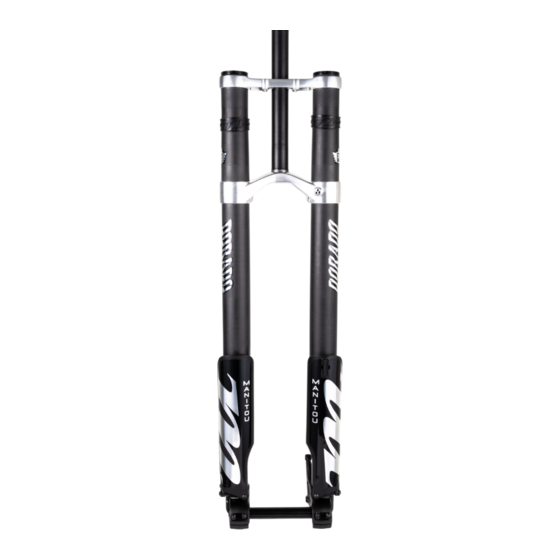
- Page 1 DORADO BOOST | SERVICE GUIDE DORADO BOOST SERVICE GUIDE...
- Page 2 Hayes Performance Systems 5800 W. Donges Bay Rd. Mequon, WI 53092 Tel: 888.686.3472 Email: techsupport@hayesbicycle.com Web: www.hayescomponents.com Hayes Components Europe Dirnismaning 20 a 85748 Garching (b. Munich) Germany ph: +49 (0)89 203237450 Email: techsupportEU@hayesbicycle.com Web: www.hayescomponents.com DORADO BOOST SERVICE GUIDE...
- Page 3 Please read through the required tools page and be sure you have all of the items you will need for the service of your fork. The guide is designed to be used with the Dorado Boost Service kit which includes all O-rings and seals to overhaul the fork.
- Page 4 Damping Leg Service - Assembly 11–13 Air Leg Service - Disassembly 14–15 Compression Rod Service 16–20 Air Leg Service - Assembly 21–22 Dust and Oil Seal Replacement 23–24 Exploded Diagram & Parts List 25–26 O-Ring Placement Diagrams 27–30 DORADO BOOST SERVICE GUIDE...
-
Page 5: Required Tools
REQUIRED TOOLS Below is a list of tools that will be used in the complete service of a Dorado Boost fork. Dorado Clamp Blocks – Manitou Part Number 172-25077 Dorado Seal Press – Manitou Part Number 172-29862 Dorado Service Kit – Includes all O-rings and seals for service. Part number 141-25995 5wt Maxima Fork oil - Manitou part number 85-0023 Slickoleum™... - Page 6 FIG. 2 drainage pan. Holding the inner leg over a drainage pan, stroke the rebound shaft several times to drain the rest of the oil from the inner leg. FIG. 3 DORADO BOOST SERVICE GUIDE...
- Page 7 (FIG. 7) Once the c-clip is removed pull the knob up. Be sure to capture the O-ring, 2 detent balls and springs FIG. 6 under the knob. (FIG. 8) FIG. 4 FIG. 7 FIG. 8 FIG. 5 DORADO BOOST SERVICE GUIDE...
- Page 8 FIG. 10 pression assembly. If it comes out with the rebound, pull the tube off of the assembly.) (FIG. 11 & 12) FIG. 11 FIG. 9 FIG. 12 DORADO BOOST SERVICE GUIDE...
- Page 9 B. O-ring #100-121 - This is the larger O-ring on the bottom out end cap. (FIG. 14) C. O-ring #100-014 - This is the smaller O-ring on the FIG. 13 bottom out end cap. (FIG. 15) FIG. 14 FIG. 15 DORADO BOOST SERVICE GUIDE...
- Page 10 Remove the top cap and nylon washer from the assembly. This is required to replace the O-rings includ- (FIG. 19) ed in the service kit for the compression assembly. FIG. 17 FIG. 16 FIG. 18 FIG. 19 DORADO BOOST SERVICE GUIDE...
- Page 11 C. O-ring # 101-1250-200 - This O-ring is located just below the top opening on the top cap where the adjuster slides through. (FIG. 22) Press the top cap back onto the compression assembly. (FIG. 23) FIG. 21 FIG. 20 FIG. 22 FIG. 23 DORADO BOOST SERVICE GUIDE...
- Page 12 Install the assembly in the inner leg by sliding it into the bottom of the leg. Use a 26mm socket to tighten it into the leg. Tighten to 6.8 N m (60 in lb). (FIG. 3) FIG. 2 FIG. 3 DORADO BOOST SERVICE GUIDE...
- Page 13 TPC+ knob and apply a small amount of grease to it. (FIG. 7) FIG. 6 Install the TPC+ adjuster knob onto the end cap and secure with the 2mm screw. (FIG. 8) FIG. 7 FIG. 4 FIG. 8 FIG. 5 DORADO BOOST SERVICE GUIDE...
- Page 14 36mm wrench to the proper torque of 6.8-9.0 N m (60-80 in lb). Reinstall the damping leg into the fork crowns on the bike. FIG. 11 DORADO BOOST SERVICE GUIDE...
- Page 15 36mm wrench. Remove the top cap from the compression rod with a 13mm wrench on the top of the compression rod and a 36mm wrench. (FIG. 4) FIG. 3 FIG. 4 FIG. 1 DORADO BOOST SERVICE GUIDE...
- Page 16 Remove Compression Rod Assembly from the in- ner leg. Note: there may be a small amount of Semi- FIG. 5 bath oil on top of the piston. Remove Semi-bath, this will be replaced with Slickoleum™ grease (FIG. 7) FIG. 6 FIG. 7 DORADO BOOST SERVICE GUIDE...
- Page 17 (FIG. 4) Keep turning the wrench until the valve shaft stops moving out of the housing. FIG. 3 FIG. 4 FIG. 1 DORADO BOOST SERVICE GUIDE...
- Page 18 (FIG. 8) Be careful when removing the piston as there is a small spring in the shaft under the piston. (FIG. 9) FIG. 7 FIG. 5 FIG. 8 FIG. 9 FIG. 6 DORADO BOOST SERVICE GUIDE...
- Page 19 Replace O-ring #100-214 on the air piston. (FIG. 13A) Forks produced in 2017 and after will have the updated piston. (FIG. 13B) Replace Quad Seal #110-214 on the air piston. FIG. 12 FIG. 10 FIG. 13A FIG. 11 FIG. 13B DORADO BOOST SERVICE GUIDE...
- Page 20 Tighten to 5.1 - 6.2 N m (45 -55 in lb) (FIG. 17 & 18) FIG. 16 FIG. 14 FIG. 17 FIG. 15 FIG. 18 DORADO BOOST SERVICE GUIDE...
- Page 21 (FIG. 22) Turn the poppet clockwise, threading it onto the valve shaft. Tight- FIG. 21 en it until the valve shaft protrudes from the valve housing 1mm. (FIG. 23) FIG. 19 FIG. 22 FIG. 20 FIG. 23 DORADO BOOST SERVICE GUIDE...
- Page 22 Grease. (FIG. 2) Slide the inner leg into the outer leg, and clamp the top of the outer leg in the bike stand. Replace O-ring #100-027 on the top cap. (FIG. 3) FIG. 2 FIG. 4 DORADO BOOST SERVICE GUIDE...
- Page 23 Fully extend the inner leg and tighten down the top cap to the proper torque of 6.8-9.0 N m (60-80 in lb). (FIG. 7) FIG. 5 Fill the fork to the desired air pressure. (50-90psi) FIG. 6 FIG. 7 DORADO BOOST SERVICE GUIDE...
- Page 24 Place the new dust seal into the leg and use the FIG. 2 knurled end of the Dorado Seal Press to press it complete into the leg. (FIG. 8) Install the wear ring back onto the outer leg. FIG. 3 DORADO BOOST SERVICE GUIDE...
- Page 25 LEG assembly FIG. 4 FIG. 7 FIG. 5 FIG. 8 FIG. 6 DORADO BOOST SERVICE GUIDE...
- Page 26 Boost exploded view DORADO BOOST SERVICE GUIDE...
- Page 27 DORADO BOOST SERVICE GUIDE...
- Page 28 REBOUND DAMPER ASSEMBLY O-RING PLACEMENT NOTE: O-RINGS ARE NOT TO SCALE DORADO BOOST SERVICE GUIDE...
- Page 29 SEE FIGURE A FIGURE B This is the poppet that is located inside the compression damper shaft. Please see the service manual section that shows the dissasembly of the compression rod.. NOTE: O-RINGS ARE NOT TO SCALE DORADO BOOST SERVICE GUIDE...
- Page 30 COMPRESSION DAMPER O-RING PLACEMENT 08-29433-L026 NOTE: O-RINGS ARE NOT TO SCALE DORADO BOOST SERVICE GUIDE...
- Page 31 & Compression damper assembly TOP CAP & COMPRESSION DAMPER KNOB O-RING PLACEMENT 100-024 100-025 100-027 NOTE: O-RINGS ARE NOT TO SCALE DORADO BOOST SERVICE GUIDE...
- Page 32 MANITOU 5800 W Donges Bay Rd Mequon, WI 53092 manitoumtb.com 888.686.3472 Support: manitoumtb.com/support 46-38528 REV. A...
Need help?
Do you have a question about the Dorado Boost and is the answer not in the manual?
Questions and answers