
Related Manuals for Mantracourt DCell


Summary of Contents for Mantracourt DCell
- Page 1 DCell DCell & DSC Strain Gauge or Load Cell Embedded Digitiser Module CANopen® – 2 Generation Software Version 3 onwards User Manual mantracourt.com...
-
Page 2: Table Of Contents
Shunt Calibration Commands, SCON and SCOF ..................25 Digital Output, OPON and OPOF ...................... 25 Flags ............................25 Diagnostics Flags, FLAG and STAT ....................25 Latched Warning Flags (FLAG) ......................25 Mantracourt Electronics Limited DCell & DSC CANopen® User Manual... - Page 3 Power and Communication ......................50 Temperature Sensor ........................50 Identifying Strain Gauge Connections ....................51 DCell Input Connections ........................ 51 DSC Input Connections ........................51 Identifying Bus-End Connections ...................... 51 DCell Bus Connections ........................51 Mantracourt Electronics Limited DCell & DSC CANopen® User Manual...
- Page 4 Technical Specifications DSC/DCELL High Stability ................61 Technical Specifications DSC/DCell Industrial Stability ................62 Mechanical Specification for DSC ..................... 63 Mechanical Specification for DCell ....................63 CE Approvals ..........................63 Warranty ..........................64 Mantracourt Electronics Limited DCell & DSC CANopen® User Manual...
-
Page 5: Chapter 1 Introduction
The device is configurable using a CANopen® configuration tool. Key Features Ultra-miniature The DCell ‘puck’ format can be fitted inside most load cell pockets, and similar restricted spaces. The DSC cards are similarly very small, optimised for mounting as a component onto custom PCBs. High-precision Industrial Version. -
Page 6: Special Facilities
DC Excitation. DC excitation has now been employed allowing longer cable lengths for the load cells which is particularly useful for DSC. This is a 4-wire measurement. Mantracourt Electronics Limited DCell & DSC CANopen® User Manual... -
Page 7: The Product Range
The DSC lends itself to PCB mounting Additional DCell & DSC Variants Available A separate variant is available with RS232 or RS485 output. Refer to DCell & DSC CAN - 2 Generation - Manual. (These variants are sufficiently different to require their own manuals) The following order codes are supported by an earlier version manual ‘DCell &... -
Page 8: Some Application Examples
Pressure loads are taken at a number of keys points in a manufacturing process, distributed over a large area. Each pressure sensor contains a DCell unit, and all the sensors are connected by a single cable carrying power and CAN communications. A central PC allows continuous display, monitoring and logging of all values from a central control room. -
Page 9: Chapter 2 Getting Started With The Evaluation Kit
Chapter 2 Getting Started with the Evaluation Kit This chapter explains how to connect up a DCell/DSC for the first time and how to get it working. For simplicity, this chapter is based on the standard DCell/DSC Evaluation Kit, which contains everything needed to communicate with a puck or card from your PC. -
Page 10: Checking The Device Type
Initial Checks With no load cell connected The LED of the DCell or DSC should flash OFF for 100ms every 0.5s. Note: If a Load cell is connected and there are no errors then the LED will Flash ON for 100mS then Off for the above period. -
Page 11: Running The Instrument Explorer Software
From the Windows ‘Start’ button, select Programs, then Instrument Explorer or click on the shortcut on your desktop. Instrument Explorer Icon The application should open and look like the following shield shot.Instrument Explorer Window Mantracourt Electronics Limited DCell & DSC CANopen® User Manual... -
Page 12: Instrument Settings
Select the ID type. Default is 11Bit (standard note extended not supported) Now click the ‘OK’ button… The above assumes factory defaults. If your device is known to have different settings use these instead of the ones stated above. Mantracourt Electronics Limited DCell & DSC CANopen® User Manual... -
Page 13: Viewing Device Data
There are no checks on the data entered and it is up to the user to enter the correct data. Mantracourt Electronics Limited DCell & DSC CANopen® User Manual... -
Page 14: Connecting A Load Cell
Connecting a Load Cell You can now connect a strain gauge bridge, load cell or simulator to the DCell/DSC. A suitable strain gauge should have an impedance of 350-5000ohms and (at least for now) a nominal output of around 2.5mV/V. -
Page 15: Dsj1 Evaluation Board Sensor Connections
Once you have connected the load cell, you should see ‘believable’ output values, in the “SYS” parameter displayed in the parameter list pane. These values should correspond to mV/V assuming the device is in it’s factory default state. Mantracourt Electronics Limited DCell & DSC CANopen® User Manual... -
Page 16: Performing A System Calibration
A 10 tonne load cell manufacturer gives the following data: mV/V output Force 2.19053 10 tonne -0.01573 0 tonne Start the wizard by selecting Sys Calibration Table from the Wizard menu Mantracourt Electronics Limited DCell & DSC CANopen® User Manual... - Page 17 SMAX or less than SMIN. If this is the case then change these values to suitable limits. In this example we may set SMIN to –0.5 (tonne) and SMAX to 12.0 (tonne). This would then provide clamping of SYS to these values and also a flags being set in FLAG and STAT. Mantracourt Electronics Limited DCell & DSC CANopen® User Manual...
- Page 18 Apply the low known test weight and enter the required SYS value for this weight. In this case it will be 10 as we want the units of SYS to be Kg. Click Next to continue Mantracourt Electronics Limited DCell & DSC CANopen® User Manual...
- Page 19 SMIN to –0.5 (Kg) and SMAX to 110.0 (Kg). This would then provide clamping of SYS to these values and also a flags being set in FLAG and STAT. For detailed information about calibration calculations please refer to chapter 3. Mantracourt Electronics Limited DCell & DSC CANopen® User Manual...
-
Page 20: Chapter 3 Explanation Of Category Items
Invalid RATE values are treated as if it was set to 3. The underlying analogue to digital conversion rate is 1627Khz. These results are block averaged to produce the required output rate. Mantracourt Electronics Limited DCell & DSC CANopen® User Manual... -
Page 21: Dynamic Filtering, Ffst And Fflv
The following table shows the number of updates x FFST and the error % New Filter Output value will differ from a constant Input Value. x FFST % Error 36.7879441 13.5335283 4.97870684 1.83156389 0.67379470 Mantracourt Electronics Limited DCell & DSC CANopen® User Manual... -
Page 22: Cell
FFST. Cell Provides the level where the integration between the DCell/DSC and the strain gauge bridge takes place. Features include, when the optional temperature module is fitted, 5-point temperature compensation to produce a temperature compensated value CMVV. Scaling using a gain and offset, CGAI and COFS respectively, producing a value known as CRAW. -
Page 23: Two Point Calibration Calculations And Examples
Methods 1 and 2 require no load tests. This means that systematic installation errors cannot be removed, such as cells not being mounted exactly vertical. The accuracy is also limited by the DCell/DSC electrical calibration accuracy, which is about 0.1%. -
Page 24: Cell Limits, Cmin, Cmax
Test load = xA CELL reading = cA Test load = xB CELL reading = cB Then we calculate the following gain value SGAI = (xB – xA) / (cB – cA) Mantracourt Electronics Limited DCell & DSC CANopen® User Manual... -
Page 25: Example Of Calculations For Sgai And Sofs
STAT, the value of SRAW is also clamped to this value. On SRAW being less than the value set in SMIN the SRAWUR flag is set in both FLAG and STAT, the value of SRAW is also clamped to this value. Mantracourt Electronics Limited DCell & DSC CANopen® User Manual... -
Page 26: System Zero, Sz
The warning flags are generally latched indicators of transient error events: By resetting the register, the host both signals that it has seen the warning, and readies the system to detect any re-occurrence (i.e. it resets the latch). Mantracourt Electronics Limited DCell & DSC CANopen® User Manual... -
Page 27: Meaning And Operation Of Flags
NOTE This flag will also be set when the shunt calibration has been switched on. WDRST indicates that the Watchdog has caused the device to re-boot. If this error continually occurs consult factory. Mantracourt Electronics Limited DCell & DSC CANopen® User Manual... -
Page 28: Dynamic Status Flags (Stat)
5.6V and this must include any troughs in the AC element of this supply. REBOOT is set whenever the DCell/DSC is powered up and is normal for a power up condition. This flag can be used to warn of power loss to device. -
Page 29: User Storage
The reset action may take up to about a second to take effect, followed by the normal start-up pause of 1 second. WARNING: Finite Non-Volatile Memory Life The DCell and DSC use EEPROM-type memory as the storage for non-volatile controls (i.e. all the settings that are retained even when powered down). -
Page 30: Chapter 4 The Readings Process
There are also two flags, ECOMUR and ECOMOR (not shown on the diagram), which indicate an input electrical under- or over-range. Cell The ‘Cell’ calibration converts the mV/V output into a cell-force reading. Mantracourt Electronics Limited DCell & DSC CANopen® User Manual... -
Page 31: Cell And System Scaling
SYS/CELL gain factor SOFS SRAW value offset SMIN Minimum value for SRAW SMAX Maximum value for SRAW SYS value offset (MVV is mV/V, “force” is force units, and “eng” is engineering units) Mantracourt Electronics Limited DCell & DSC CANopen® User Manual... -
Page 32: Calibration Parameters Summary And Defaults
0.0, 0.0, 0,0… System Control Defaults Command Action Default Values SGAI basic gain SOFS basic offset SMIN SRAW min limit –100.0 SMAX SRAW max limit +100.0 output zero offset Mantracourt Electronics Limited DCell & DSC CANopen® User Manual... -
Page 33: Chapter 5 Temperature Compensation
The temperature module is a small double sided PCB with an 8 pin SOIC integrated circuit mounted to it. The dimensions are 10.5 x 7.6 x 2.5mm. There are two solder pads for connection to the DSC or DCell. A 2mm hole is used for fixing the temperature module to the body of the load cell. -
Page 34: Control Parameters
The actual gain value used is 1 + CALC_CTGO x 10-6 and is multiplied by the uncompensated value MVV. The offset correction is then applied. Using the same temperature index “i” as found for the GAIN index above. Mantracourt Electronics Limited DCell & DSC CANopen® User Manual... -
Page 35: The Temperature Measurement
During testing, temperatures should be measured using the internal TEMP measurement, as this is the measurement used to do the corrections. For in-system tests, the environment of the DCell/DSC must always be as near as possible to the exact conditions of the eventual in-system use. -
Page 36: Parameter Calculations
Parameter Calculations Instrument Explorer provides a “Wizard” for the calculation of the parameters required by the DSC/DCell. This is based on Method 3 where data is collected. The wizard allows for small changes in the sampled temperature point that may occur when taking a set of results for gain and offset. Also taken into account is any variation in the test weights at different temperatures. -
Page 37: Chapter 6 Linearity Compensation
The DCell/DSC non-linearity compensation uses a single ‘lookup table’, similar to those used for temperature compensation (see previous chapter). This provides a linearly-interpolated compensating value with up to 7 control points, which is then added to the output result. -
Page 38: How To Set Up Linearity Compensation
For test load of x5 = 450.03Kg : CELL reading c5 = 449.98 We choose these precise test points as our linearisation reference points, so CLN = 5 CLX1 = 0.0010 CLX2 = 100.44 Mantracourt Electronics Limited DCell & DSC CANopen® User Manual... - Page 39 However there is a big jump between points 3 and 4, which might be worth a more detailed investigation: Some important features of the error curve could have been missed by the test. Mantracourt Electronics Limited DCell & DSC CANopen® User Manual...
-
Page 40: Chapter 7 Self-Diagnostics
LED will invert. IE the LED will flash off for 100mS at the rate set in the table above. These flags Being, TEMPUR, TEMPOR, ECOMUR, ECOMOR, CRAWUR, CRAWOR, SYSUR, SYSOR & LCINTEG. Mantracourt Electronics Limited DCell & DSC CANopen® User Manual... -
Page 41: Chapter 8 Canopen® Communication Protocol
This chapter gives details of communication protocols and bus connections. This manual only covers CANopen® communications The user will need a suitable CANopen® bus-master application to communicate with DSC. (Details of suitable solutions are available from Mantracourt on request). CANopen® Features Support Summary Device Profile... -
Page 42: Object Dictionary Summary
Object Dictionary Summary DSC & DCELL internal data values are mapped into the object dictionary in three distinct areas :– 1. The main output values are mapped into the ‘Device Profile’ area, at 6000h onward 2. Special control parameters, specific to the CANopen® version, are at 2000h onward 3. -
Page 43: Error Management
Again stored in non volatile memory and changes will not take effect until the unit is power cycled. On receiving a NMT “Reset_Node” or “Reset_Communication” service, all the device-independent communications settings revert to the CANopen® standard default settings. The Node-ID and Bit Rate are not reset by this. Mantracourt Electronics Limited DCell & DSC CANopen® User Manual... -
Page 44: Data Type Conversions And Rounding
240, 240.1 and 239.66 are all the same value Rounding Although rounding is applied when writing to integral values, data read from a device is not rounded off. Mantracourt Electronics Limited DCell & DSC CANopen® User Manual... -
Page 45: Chapter 9 Object Dictionary
Chapter 9 Object Dictionary This chapter contains tables of all DCell/DSC Object Dictionary, with brief details of each. Communications Profile Area Device Description and Communication Specific Name Description Access Object Object Data Type Dictionary Dictionary Index Sub Index DEVICE TYPE... -
Page 46: Transmit Pdo Operation Specific
2. PDO Parameters are stored directly to non volatile memory but will not take effect until the device has been re-booted or an NMT reset communications has been issued. 3. 0x80000000 disables the TxPDO otherwise, setting a non zero value will result in this value being used instead. Mantracourt Electronics Limited DCell & DSC CANopen® User Manual... -
Page 47: Transmit Pdo Mapping Specific
Forth byte is the required data length Note: The TxPDOs defaults have been mapped to the Manufacturers Specific Profile Area and not the Standardised Device Profile Area. Name refers to the Instrument Explorer Name. Mantracourt Electronics Limited DCell & DSC CANopen® User Manual... -
Page 48: Manufacturer Specific Area
“..” - Denotes a range (e.g. CLK1..7 means “CLK1” to “CLK7”) C = Caar 1 Byte Access RW/RO/WO/X = read-write / read-only / write-only / execute I = Integer 2 Byte Mantracourt Electronics Limited DCell & DSC CANopen® User Manual... - Page 49 Mantracourt Electronics Limited DCell & DSC CANopen® User Manual...
-
Page 50: Chapter 10 Installation
DCell is normally sealed in the pocket of the load cell, which provides mechanical and moisture protection, and electrical shielding. The DCell should be mounted using a 2mm screw to the body of the load cell. This should be a “Good” electrical connection to obtain maximum performance. -
Page 51: Soldering Methods
2. DCell units can be damaged by poor soldering, due to the small nature of the circuit boards: Overheating or applying any pressure to a pad can de solder components on the other side of the board, or cause the pad itself to become detached. -
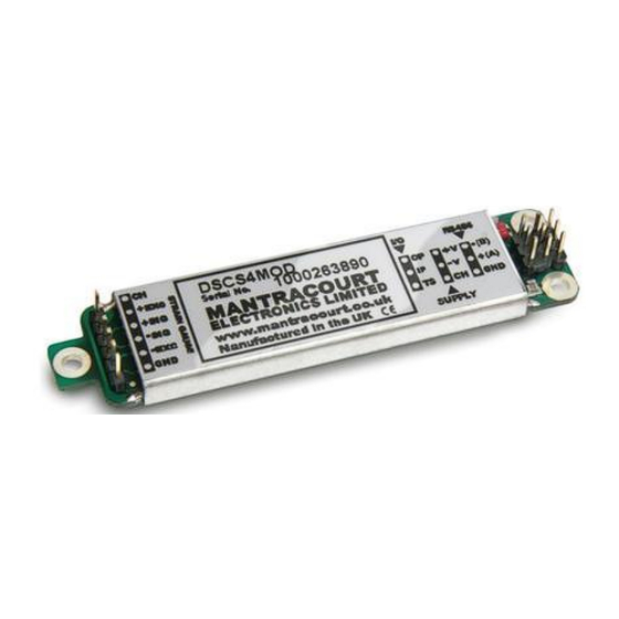
Page 52: Identifying Strain Gauge Connections
GND can be used as the ground connection for the temperature sensor Other Connections (DSC ONLY) Resistor RG and track-cut TC are used to adjust the mV/V sensitivity (see Strain Gauge Sensitivity Adjustment, below). Identifying Bus-End Connections DCell Bus Connections CANL CANH Mantracourt Electronics Limited DCell & DSC CANopen® User Manual... -
Page 53: Dsc Can Versions-Bus Connections
The EXC+/– wires should be twisted together, also the SIG+/– pair, and the two pairs kept apart. It is also recommended to secure the wires from moving due to shock or vibration. If the DCell is mounted outside the body of the load cell then, for optimal performance, twin twisted cable should be used, although standard 4 core shield cable can be used in low noise environments. -
Page 54: Dsc Strain Gauge Cabling Arrangement
2 twisted-pair version, otherwise similar to the above. A suitable type is BICC Brand-Rex PD3003 (also equivalent to Belden type 8777). In the UK, this is available from Farnell (enter ‘Belden 8777’ for real length options). Mantracourt Electronics Limited DCell & DSC CANopen® User Manual... -
Page 55: Communications Cabling And Grounding Requirements
There MUST be a common connection from the PSU and the CAN ground to ensure the CAN stays within the required common mode voltage of -2v (CANL) to +7v (CANH). The shield should be connected to the grounded enclosure of the power supply. Mantracourt Electronics Limited DCell & DSC CANopen® User Manual... -
Page 56: Dsc4 Versions- Power And Communications Wiring
A suitable type is BICC Brand-Rex BE56723 (also equivalent to Belden type 8723). In the UK, this is available from Farnell, part number 118-2117 For bit rates above 500Kbps the following is recommended Belden B3084A Belden B8132 Mantracourt Electronics Limited DCell & DSC CANopen® User Manual... -
Page 57: Can Bus Connections For Multiple Dcells
Pair 120R Terminating Resistor 120R Terminating Twisted Resistor Pair CANH CANL CAN GND Note : The specified cable above shows a yellow wire this will be replaced with a white wire. Mantracourt Electronics Limited DCell & DSC CANopen® User Manual... -
Page 58: Key Requirements
It is important that the bus is loaded at each end with the corresponding line impedance, this is normally 120Ohm Strain Gauge Sensitivity Adjustment (DSC ONLY) For DCell strain gauge sensitivity adjustment please consult factory. If your strain gauge does not deliver a 2.5mV/V full scale output, you may want to adjust the sensitivity of the electronics (hardware) and/or the software gain controls. - Page 59 2. The sensitivity should, however, not be set greater than typically 1mV/V: Beyond this, input noise usually dominates and no extra benefit can be achieved. Mantracourt Electronics Limited DCell & DSC CANopen® User Manual...
-
Page 60: Chapter 11 Troubleshooting
Chapter 11 Troubleshooting This chapter gives a quick guide to problem solving for DCell/DSC devices. Bear in mind that the quickest way to pin down problems is to usually replace items with ‘known good’ alternatives. This also applies to cables, power supplies, devices etc. -
Page 61: Unexpected Warning Flags
2 seconds of First Command Byte ASCII Blank DECIMAL Blank Blank After sending the command sequence recycle the power to the DSC the DSC will then have the default base ID of 1. Mantracourt Electronics Limited DCell & DSC CANopen® User Manual... -
Page 62: Chapter 12 Specifications
1. From original offset at any time 2. 1st Year 3. Dependent on cable type and bit rate. The DSC digital output is an open collector transistor rated at 100mA @ 40v Mantracourt Electronics Limited DCell & DSC CANopen® User Manual... -
Page 63: Technical Specifications Dsc/Dcell Industrial Stability
1. From original offset at any time 2. 1st Year 3. Dependent on cable type and bit rate The DSC digital output is an open collector transistor rated at 100mA @ 40v Mantracourt Electronics Limited DCell & DSC CANopen® User Manual... -
Page 64: Mechanical Specification For Dsc
87.4 Mechanical Specification for DCell DCell : Diameter 20mm, Height 10mm and has an 2mm mounting hole to accept M2 screw or American equivalent #0-80. Important Note: DO NOT USE #2 screw size. Hole centre positions taken from pcb centre. -
Page 65: Warranty
(3) three years from the date of dispatch. If the 'Mantracourt' product you purchase appears to have a defect in material or workmanship or fails during normal use within the period, please contact your Distributor, who will assist you in resolving the problem. If it is necessary to return the product to 'Mantracourt' please include a note stating name, company, address, phone number and a detailed description of the problem.
Need help?
Do you have a question about the DCell and is the answer not in the manual?
Questions and answers