
Subscribe to Our Youtube Channel
Related Manuals for Mantracourt DSC


Summary of Contents for Mantracourt DSC
- Page 1 DCell DCell & DSC Strain Gauge or Load Cell Embedded Digitiser Module – 2 Generation Software Version 3 onwards User Manual Micron Meters Web: www.micronmeters.com Email: metersinfo@micronmeters.com...
-
Page 2: Table Of Contents
Communications ......................... 22 Station Number, STN ........................22 Baud rate Control, BAUD ....................... 23 Reset: New For Version 4 (DSC Only) ....................23 DSC Issue 3 pcb or Higher ......................23 Communications Failure Count, CFCT ....................24 Output Format Controls, DP and DPB (ASCII ONLY) ................24 Information .......................... - Page 3 Data Type Conversions and Rounding ....................47 The ASCII Protocol ........................48 Continuous Output Stream (ASCII ONLY)..................... 50 New for Version 4 ........................50 The MODBUS-RTU Protocol ......................50 The Mantrabus-II Protocol ......................52 Micron Meters DCell & DSC User Manual...
- Page 4 RS232 Bus Layout ........................64 RS485 Bus Layout ........................64 RS485 Bus Connections for Multiple DCells ..................65 RS485 Bus Connections for Multiple DSC RS485 Versions ................. 65 RS232 & RS485 Bus Converters ......................66 Strain Gauge Sensitivity Adjustment (DSC ONLY) .................. 67 Identifying the DSC ‘Rg’...
-
Page 5: Chapter 1 Introduction
Key Features Ultra-miniature The DCell ‘puck’ format can be fitted inside most load cell pockets, and similar restricted spaces. The DSC cards are similarly very small, optimised for mounting as a component onto custom PCBs. High-precision Industrial Version. -
Page 6: Special Facilities
• Peak & Trough Measurements. Added to allow the faster rates to hold a peak or trough readings. These are stored in volatile memory & are therefore reset on power up. Micron Meters DCell & DSC User Manual... -
Page 7: Version 4 Additions And Enhancements
Version 4 Additions and Enhancements • Reset to default communication parameters. A pair of pads on the underside of the DSC, when shorted together at power up will reset Station no. to 1 and baudrate to 115200 Note: This is only for issue 3 pcb and higher. Please refer to underside for issue marking. -
Page 8: Additional Dcell & Dsc Variants Available
Differences Only the DSC (card) is available with the RS232 output option and has the digital Input & output. Special Aspects To Consider The DCell fits neatly into a strain gauge pocket The DSC lends itself to PCB mounting The RS485 output version must be used for multiple devices on the same bus Additional DCell &... -
Page 9: Some Application Examples
A lorry loading weighpoint monitors left/right load balance and sounds a warning if loading is too uneven for safety. A drive-on weighing platform is provided with load cells at each of four corners. Each cell is wired to a DSC unit, and these are cabled to a 3 party LCD display and control unit, producing a complete turnkey system. -
Page 10: Chapter 2 Getting Started With The Evaluation Kit
Chapter 2 Getting Started with the Evaluation Kit This chapter explains how to connect up a DCell/DSC for the first time and how to get it working. For simplicity, this chapter is based on the standard DCell/DSC Evaluation Kit, which contains everything needed to communicate with a puck or card from your PC. -
Page 11: Checking The Device Protocol Type And Station Number
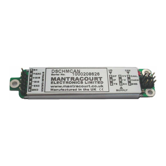
For DSC the product label shows the product code which determines the protocol and its serial number. For the DCell the serial number is it’s only means of identification. The serial number must be used to cross reference the dispatch note to identify the protocol of the device. -
Page 12: Initial Checks
Initial Checks With no load cell connected The LED of the DCell or DSC should flash OFF for 100ms every 0.5, 1 or 2 seconds depending on protocol. See following table. Protocol LED Flash Period ASCII 0.5 seconds MODBUS 1 second... -
Page 13: Instrument Explorer Icon
A list of available instruments is displayed in the Select Instrument pane of Instrument Explorer. Select the relevant device and protocol, to match the device you are working with, by clicking on the required device icon. Micron Meters DCell & DSC User Manual... -
Page 14: Instrument Settings
• Select the Station No. / Node. The factory default is 1. • Now click the ‘OK’ button… The above assumes factory defaults. If your device is known to have different settings use these instead of the ones stated above. Micron Meters DCell & DSC User Manual... -
Page 15: Viewing Device Data
There are no checks on the data entered and it is up to the user to enter the correct data. Read-Only – These parameter values are displayed ‘greyed out’ and cannot be changed. Micron Meters DCell & DSC User Manual... -
Page 16: Connecting A Load Cell
Connecting a Load Cell You can now connect a strain gauge bridge, load cell or simulator to the DCell/DSC. A suitable strain gauge should have an impedance of 350-5000ohms and (at least for now) a nominal output of around 2.5mV/V. -
Page 17: Dsj1 Evaluation Board Sensor Connections
This now exposes more levels that can be expanded as required by clicking the next to the heading name. Dynamic values (such as SYS and SRAW) will now be updating in real-time from the device. Micron Meters DCell & DSC User Manual... -
Page 18: Performing A System Calibration
Since we are now calibrating at system level we have a choice of two calibration methods: Sys Calibration Table – This technique is used when a manufacturers calibration document is available for the connected strain gauge. This normally gives mV/V to engineering unit values. Micron Meters DCell & DSC User Manual... -
Page 19: Sys Calibration, Table Method
Force 2.19053 10 tonne -0.01573 0 tonne Start the wizard by selecting Sys Calibration Table from the Wizard menu Click the Next button and enter the low values as shown below. Micron Meters DCell & DSC User Manual... -
Page 20: Sys Calibration, Auto Method
FLAG and STAT. Sys Calibration, Auto Method Assume we require to calibrate for Kg output and we have available a known accurate 10 Kg and 100 Kg test weights. Micron Meters DCell & DSC User Manual... - Page 21 SYS to be Kg. Click Next to continue Apply the high known test weight and enter the required SYS value for this weight. In this case it will be 100. Click Next to continue. Micron Meters DCell & DSC User Manual...
- Page 22 SMIN to –0.5 (Kg) and SMAX to 110.0 (Kg). This would then provide clamping of SYS to these values and also a flags being set in FLAG and STAT. For detailed information about calibration calculations please refer to chapter 3. Micron Meters DCell & DSC User Manual...
-
Page 23: Chapter 3 Explanation Of Category Items
The STN parameter controls the ‘station number’, which specifies the device address for bus communications. As supplied, devices have the station-number factory set to 1, as described previously in Version 3 Additions and Enhancements, Chapter 1. Micron Meters DCell & DSC User Manual... -
Page 24: Baud Rate Control, Baud
With version 3 pcb and higher. A reset to comms defaults is available. This will return Station No. to 1 and baudrate to 115200. This is achieved by powering off the DSC shorting the 2 pads together whilst powering DSC Issue 3 pcb or Higher... -
Page 25: Communications Failure Count, Cfct
The VER parameter (read-only byte) returns a value identifying the software release number, coded as 256*(major- release)+(minor-release) eg. current version 3.1 returns VER=769 Serial Number, SERL and SERH SERL and SERH are read-only integer parameters returning the device serial-number. This is decoded as = 65536*SERH + SERL. Micron Meters DCell & DSC User Manual... -
Page 26: Strain Gauge
1, that is to say that output of the filter will be equal to the new input reading. If the difference is less than FFLV then the fractional amount added is Micron Meters DCell & DSC User Manual... - Page 27 0.00022603 0.00008315 0.00003059 0.00001125 0.00000414 0.00000152 0.00000056 0.00000021 Remember that if the step change in mV/V is greater than the value set in FFLV then New Filter Output value = New Input Value. Micron Meters DCell & DSC User Manual...
-
Page 28: Cell
FFST. Cell Provides the level where the integration between the DCell/DSC and the strain gauge bridge takes place. Features include, when the optional temperature module is fitted, 5-point temperature compensation to produce a temperature compensated value CMVV. Scaling using a gain and offset, CGAI and COFS respectively, producing a value known as CRAW. -
Page 29: Cell Limits, Cmin, Cmax
Methods 1 and 2 require no load tests. This means that systematic installation errors cannot be removed, such as cells not being mounted exactly vertical. The accuracy is also limited by the DCell/DSC electrical calibration accuracy, which is about 0.1%. -
Page 30: Linearisation In Brief
CELL reading cB = 498.7735 Calculate gain value. In this case put SGAI = (xB – xA) / (cB – cA) = (0.50007 – 0.09988) / (498.7735 – 100.0112) ≈ 0.001003580 = 1.003580x10 Micron Meters DCell & DSC User Manual... -
Page 31: System Limits, Smin, Smax
Note: Instrument Explorer provides “wizards” for easy calibration of the System stage. There are two wizards, ‘Sys Calibration Auto’ and ‘Sys Calibration Table’ these can be found under the menu item “Wizards”. Micron Meters DCell & DSC User Manual... -
Page 32: Control
Digital Output, OPON and OPOF For DSC ONLY an open collector output is available. This can be switched on using OPON and off by the command OPOF. This output is capable of switching 100mA at 30v (TBC) -
Page 33: Dynamic Status Flags (Stat)
5.6V and this must include any troughs in the AC element of this supply. REBOOT is set whenever the DCell/DSC is powered up and is normal for a power up condition. This flag can be used to warn of power loss to device. -
Page 34: Output Update Tracking
SPSTAT indicates the state of the Open collector output, 1 being output on 0 being output off. IPSTAT indicates the state of the digital input (Only available on DSC model). Bit set indicates input is ‘closed’ to 0v (-V or GND). -
Page 35: Chapter 4 The Readings Process
– Electrical The ‘Electrical’ calibration produces corrected electrical readings from the internal measurements. This is factory-set by Mantracourt during the production process. The main outputs from this are – • MVV is the factory calibrated output, in mV/V units. -
Page 36: Cell And System Scaling
SYS/CELL gain factor SGAI Eng/ Force SRAW value offset SOFS SMIN Minimum value for SRAW Maximum value for SRAW SMAX SYS value offset (MVV is mV/V, “force” is force units, and “eng” is engineering units) Micron Meters DCell & DSC User Manual... -
Page 37: Calibration Parameters Summary And Defaults
0.0, 0.0, 0,0… CLK1..7 linearity adjusts 0.0, 0.0, 0,0… System Control Defaults Command Action Default Values SGAI basic gain SOFS basic offset SMIN SRAW min limit –100.0 SMAX SRAW max limit +100.0 output zero offset Micron Meters DCell & DSC User Manual... -
Page 38: Chapter 5 Temperature Compensation
One connection is ground for which –EXC is used and the other is the 1 wire “DQ” connection which provides the bi- directional data line. DSC connections to DTEMP For the DSC “TS” on the I/O connector is connected to “DQ” of the DTEMP module and “GND” of the DSC is connected to “-EXC” Micron Meters... -
Page 39: Control Parameters
The temperature module is a small double sided PCB with an 8 pin SOIC integrated circuit mounted to it. The dimensions are 10.5 x 7.6 x 2.5mm. There are two solder pads for connection to the DSC or DCell. A 2mm hole is used for fixing the temperature module to the body of the load cell. -
Page 40: The Temperature Measurement
The best possible compensation for a given piece of physical hardware can only be achieved by performing experiments on that particular unit (DCell/DSC and associated strain gauges), to characterise the measurement output at a variety of different, stable temperatures in the required operating range. -
Page 41: Parameter Calculations
During testing, temperatures should be measured using the internal TEMP measurement, as this is the measurement used to do the corrections. For in-system tests, the environment of the DCell/DSC must always be as near as possible to the exact conditions of the eventual in-system use. -
Page 42: Chapter 6 Linearity Compensation
The DCell/DSC non-linearity compensation uses a single ‘lookup table’, similar to those used for temperature compensation (see previous chapter). This provides a linearly-interpolated compensating value with up to 7 control points, which is then added to the output result. -
Page 43: How To Set Up Linearity Compensation
For test load of x5 = 450.03Kg : CELL reading c5 = 449.98 We choose these precise test points as our linearisation reference points, so CLN = 5 CLX1 = 0.0010 CLX2 = 100.44 CLX3 = 200.57 CLX4 = 349.75 Micron Meters DCell & DSC User Manual... - Page 44 However there is a big jump between points 3 and 4, which might be worth a more detailed investigation: Some important features of the error curve could have been missed by the test. Micron Meters DCell & DSC User Manual...
-
Page 45: Chapter 7 Self-Diagnostics
If an error conditions occurs which is based on any of the following error flags being set then the operation of the LED will invert. IE the LED will flash off for 100mS at the rate set in the table above. These flags Being, TEMPUR, TEMPOR, ECOMUR, ECOMOR, CRAWUR, CRAWOR, SYSUR, SYSOR & LCINTEG. Micron Meters DCell & DSC User Manual... -
Page 46: Chapter 8 Communication Protocols
Choice of Bus Formats Essentially, the RS232 bus is only suitable where the application will only ever need a single DCell/DSC device. The only real advantage of RS232 output is that no data converter is required to connect the device to a PC. -
Page 47: The Rs485 Bus Standard
ASCII Communications Software for the Different Protocols To access a DCell/DSC, you will need a communications application running on your PC or PLC, in addition to the appropriate hardware connections. The simplest approach for initial experiments is to use the Instrument Explorer evaluation application. -
Page 48: Common Features Of All Protocols
The communications protocols are all of the master/slave type: A central ‘host’ device (normally a PC or PLC) acts as a bus master, in control of all communications. Communications consist of the master transmitting command messages addressed to particular DCell/DSC ‘slave’ devices. The target slave may then transmit a ‘response message’ back to the master. -
Page 49: The Ascii Protocol
There Are Several Possible Reasons For A NAK Response Command identifier not recognised Badly formatted command: Missing command identifier, unrecognised access-code character, or unexpected character somewhere else Access attempted not supported by this command. Micron Meters DCell & DSC User Manual... - Page 50 - there is no response Bad Commands If any command is not understood by the device then a “?” is transmitted followed by a <CR>. Example: A unrecognised command, correctly addressed to station 173 – !173:XYWR?<CR> Micron Meters DCell & DSC User Manual...
-
Page 51: Continuous Output Stream (Ascii Only)
The MODBUS protocol is a partial implementation of the “RTU” (binary) form of the MODBUS standard, sufficient to allow DCell/DSC units to coexist on a serial bus with other MODBUS-compliant devices. NOTE: Third-party applications for MODBUS communications are readily available (e.g. ModScan from Win-Tech software, www.win-tech.com, who offer a free trial version). - Page 52 3F 9D second=upper register (18) value = hi,lo 6B AB checksum = hi,lo A Correct Response Would Then Be [hex] station address info copied from command ... 00 38 00 02 C0 50 checksum = hi,lo Micron Meters DCell & DSC User Manual...
-
Page 53: The Mantrabus-Ii Protocol
The byte containing the sign & exponent is sent first, with the LS byte of the mantissa being last. The Memory Layout Of The 4-Byte Floating-Point Numbers Is: Sign bit , 1=negate Exponent, 30-23 7-bit excess-127 Mantissa, 22-0 23-bit fraction with implicit 1 Micron Meters DCell & DSC User Manual... - Page 54 Assuming the value was -12345.678 (coded as C640E6B6h, representing -1 * 2 * 12345.678 / 8192), the response will be – 14h, 0Ch, 06h, 04h, 00h, 0Eh, 06h, 0Bh, 06h, 01h, 0Fh DATA [EXOR CS] Station number Micron Meters DCell & DSC User Manual...
- Page 55 To reset station three (command 100), send the following.– FEh, 03h, E4h, 0Eh, 07h [EXOR CS] Frame Station Cmd with char number MS bit set The response is then – 03h, 06h Micron Meters DCell & DSC User Manual...
-
Page 56: Chapter 9 Software Command Reference
Chapter 9 Software Command Reference This chapter contains tables of all DCell/DSC commands, with brief details of each. Commands in Access Order ASCII name description datatype access MB reg MD reg CMVV Temp Compensated mV/V float STAT Status Filtered & factory calibrated... - Page 57 Datatype float/int/byte/– = 4-byte real / two-byte integer / 1-byte integer / none MB reg = register number for MANTRABUS protocol MD reg = start register address (always odd) for MODBUS protocol NOTES: All Modbus accesses are in register pairs, Modbus addresses are just (2*MANTRABUS)+1 Micron Meters DCell & DSC User Manual...
-
Page 58: Chapter 10 Installation
NOT PROTECTED AGAINST REVERSE POLARITY OF SUPPLY. Moisture Protection Both DCell and DSC must only be operated in a dry environment, as moisture can dramatically degrade the measurement performance. DCell Will normally be sealed into a load cell pocket. -
Page 59: Soldering Methods
(up to 1W on a 15V supply). DSC no additional electrical shielding is required, but moisture and/or mechanical protection are often required. Any simple box or enclosure can be used. If metal, the enclosure should be grounded to the SH connection (see Communications Cabling and Grounding Requirements below). -
Page 60: Temperature Sensor
A shielded twisted pair is recommended, with a maximum length of 10m the shield being connected to the load cell body or (SH if DSC). For short lengths (< 2m) in a low noise environment (inside load cell body for example) then normal cable can be used. -
Page 61: Identifying Bus-End Connections
• TS connects to DQ of the optional temperature sensor DSC2-RS232-Bus Connections • +V and -V are the DC power-supply and return connections • RX and TX are RS232 communications connections. RX being the DSC’s receive • GND is a communications ground connection • SH is the shield connection... -
Page 62: Strain Gauge Cabling And Grounding Requirements
The M2 mounting hole must be grounded via an M2 screw to the load cell body for specified performance to be met. (The 2mm mounting hole to accept M2 screw or American equivalent #0-80. Important Note: DO NOT USE #2 screw size.) Micron Meters DCell & DSC User Manual... -
Page 63: Dsc Strain Gauge Cabling Arrangement
There MUST be a common connection from the PSU and the RS485 ground to ensure the RS485 stays within the required common mode voltage of +/- 7v. The shield should be connected to the grounded enclosure of the power supply. Micron Meters DCell & DSC User Manual... -
Page 64: Dsc4-Rs485 Versions- Power And Communications Wiring
The cable shield must be connected to the SH pin at the DSC end, and not at the host end. Any further metal housing should also be connected to the DSC SH pin, and should not be connected to the bus cable shield (or the sensor cable). -
Page 65: Suitable Cable Types
PC is powered off the mains. When such a system hosts a DCell/DSC bus, the whole arrangement may be connected to the mains ground only via the external power-supply or the ground connections to the data-converter or the DCell/DSC units. -
Page 66: Rs485 Bus Connections For Multiple Dcells
120R Terminating Twisted Resistor Pair RS485 Device Note: The specified cable above shows a yellow wire this will be replaced with a white wire. RS485 Bus Connections for Multiple DSC RS485 Versions Twisted Pair 120R Terminating Resistor 120R Terminating Twisted... -
Page 67: Rs232 & Rs485 Bus Converters
RS232 & RS485 Bus Converters Typical DCell/DSC applications use a PC or PLC host, connecting via an RS232 port. This then requires an RS232 to RS485 bus converter to communicate with the bus. -
Page 68: Strain Gauge Sensitivity Adjustment (Dsc Only)
If it is less, you can correct in software alone, but increasing sensitivity will generally improve accuracy. To adjust the mV/V for DSC, an extra resistor ‘Rg’ is fitted across the pads RG, as shown above, in Identifying the DSC ‘Rg’ Resistor... -
Page 69: Chapter 11 Troubleshooting
Chapter 11 Troubleshooting This chapter gives a quick guide to problem solving for DCell/DSC devices. Bear in mind that the quickest way to pin down problems is to usually replace items with ‘known good’ alternatives. This also applies to cables, power supplies, devices etc. -
Page 70: Bad Readings
5. Check the sensor is connected properly, and has some resistance across excitation wires, and around 350 Ohms across output wires (when disconnected from device). 6. Check for damaged DCell/DSC device by replacement Unexpected Warning Flags Remember that all warning flags in FLAG must be explicitly reset –they do not clear themselves when a problem is resolved. -
Page 71: Problems With Bus Baud Rate
The only solution is to remove one device from the bus and connect it exclusively to a PC to change its STN. Always remember that a reboot (power-off or RST command) is needed to change STN and BAUD settings! Micron Meters DCell & DSC User Manual... -
Page 72: Chapter 12 Specifications
1. From original offset at any time 2. 1st Year 3. Dependent on cable type and is for RS485, For RS232 max length is 20m The DSC digital output is an open collector transistor rated at 100mA @ 40v Micron Meters DCell & DSC User Manual... -
Page 73: Technical Specifications Dsc/Dcell Industrial Stability
1. From original offset at any time 2. 1st Year 3. Dependent on cable type and is for RS485, For RS232 max length is 20m The DSC digital output is an open collector transistor rated at 100mA @ 40v Micron Meters DCell & DSC User Manual... -
Page 74: Mechanical Specification For Dsc
RS485+ (A) +3.6 -8.1 Temp sensor DQ -1.3 -8.8 +EXC -7.5 -4.9 +SIG -8.8 -1.5 -SIG -8.0 +3.9 -EXC -6.3 +6.1 CE Approvals European EMC Directive 2004/108/EC BS EN 61326-1:2006 BS EN 61326-2-3:2006 Micron Meters DCell & DSC User Manual... -
Page 75: Warranty
(3) three years from the date of dispatch. If the 'Mantracourt' product you purchase appears to have a defect in material or workmanship or fails during normal use within the period, please contact your Distributor, who will assist you in resolving the problem. If it is necessary to return the product to 'Mantracourt' please include a note stating name, company, address, phone number and a detailed description of the problem.
Need help?
Do you have a question about the DSC and is the answer not in the manual?
Questions and answers