Table of Contents
Advertisement
Quick Links
Ductless
Floating Air
Single Zone
R-454B Refrigerant
System
Wall Mounted Unit
Outdoor Unit
966011403_00
1
Pro
®
230-Volt:
230-Volt:
230-Volt:
THE EXPERTS IN ROOM AIR CONDITIONING
FPHW093B, FPHW123B, FPHW183B, FPHW243B
FAHFW09A3A, FAHFW12A3A, FAHFW18A3A,
FAHFW24A3A
FPHSR09A3B, FPHSR12A3B, FPHSR18A3B,
FPHSR24A3B
Advertisement
Table of Contents

Related Manuals for Friedrich FPHW093B


Summary of Contents for Friedrich FPHW093B
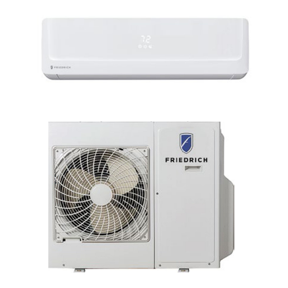
- Page 1 Ductless Floating Air ® Single Zone R-454B Refrigerant System 230-Volt: FPHW093B, FPHW123B, FPHW183B, FPHW243B Wall Mounted Unit 230-Volt: FAHFW09A3A, FAHFW12A3A, FAHFW18A3A, FAHFW24A3A Outdoor Unit 230-Volt: FPHSR09A3B, FPHSR12A3B, FPHSR18A3B, FPHSR24A3B THE EXPERTS IN ROOM AIR CONDITIONING 966011403_00...
-
Page 2: Table Of Contents
TABLE OF CONTENTS INTRODUCTION Important Safety Information Personal Injury Or Death Hazards Model And Serial Number Location Model Identification Guide Serial Number Reference Guide SPECIFICATION 9-24k (230v) Room Size Restriction Indoor Unit Clearances Outdoor Unit Clearances Dimensions FAHFW09A3A, FAHFW12A3A Dimensions FAHFW18A3A, Dimensions FAHFW24A3A, Dimensions FPHSR09A3B, FPSHR12A3B Dimensions FPHSR18A3B... - Page 3 Refrigerant Removal, Recovery, and Evacuation Component Replacement/Brazing Refrigerant Charging Triple Evacuation Compressor Replacement Replace The Reversing Valve WIRING DIAGRAMS Indoor Unit FAHFW09A3A, FAHFW12A3A, FAHFW18A3A, FAHFW24A3A Outdoor Unit FPHSR09A3B, FPHSR12A3B, FPHSR18A3B FPHSR4A3B APPENDIX Interactive Parts Viewer Limited Warranty Thermistor Resistance Values Friedrich Authorized Parts Depots...
-
Page 4: Introduction
Installation procedures are not given in this manual. They are given in the Installation/Operation manual which can be acquired on the Friedrich website. Click the Link or scan the QR code to be directed to the Professional page where you can locate our technical literature. -
Page 5: Personal Injury Or Death Hazards
INTRODUCTION Personal Injury Or Death Hazards WARNING AVERTISSEMENT ADVERTENCIA SAFETY Do not remove, disable Ne pas supprime, désacti- No eliminar, desactivar o or bypass this unit’s ver ou contourner cette pasar por alto los dispositi- FIRST safety devices. Doing so l´unité... -
Page 6: Mechanical Hazards
INTRODUCTION PERSONAL INJURY OR DEATH HAZARDS • REFRIGERATION SYSTEM REPAIR HAZARDS: Use approved standard refrigerant recovering procedures and equipment to relieve high pressure before opening system for • repair. Reference EPA regulations (40 CFR Part 82, Subpart F ) Section 608. •... - Page 7 CAUTION: Do Not Operate Equipment During Active Stages Of Construction To ensure proper operation, Friedrich requires that all equipment is not operated during active construction phases. This includes active stages of completing framing, drywalling, spackling, sanding, painting, flooring, and moulding in the equipment’s designated conditioning space. The use of this equipment during construction could result in premature failure of the components and/or system and is in violation of our standard warranty guidelines.
-
Page 8: Model And Serial Number Location
INTRODUCTION Model And Serial Number Location Early Production models of the A2L Indoor heads are marked as R-454B. These heads are compatible Indoor Unit with both R-32 and R-454B On side of Unit Refrigerant. Later models have the R-454B designation removed. Lorem ipsum Figure 101 (Indoor Unit Model Nameplate location) Outdoor Unit... -
Page 9: Model Identification Guide
FIRST UNIT OF EACH MONTH = 00001 27 = 2027 28 = 2028 MONTH OF MANUFACTURE 01 = JANUARY FACTORY DESIGNATION 02 = FEBRUARY M = FRIEDRICH MTY 03 = MARCH 04 = APRIL 05 = MAY 06 = JUNE 07 = JULY... -
Page 10: Specification
SPECIFICATION Figure 201 9-24k (230v) FAHFW09A3A FAHFW12A3A FAHFW18A3A FAHFW24A3A Model No. FPHSR09A3B FPHSR12A3B FPHSR18A3B FPHSR24A3B Type T1, INVERTER T1, INVERTER T1, INVERTER T1, INVERTER Performance Cooling Capacity (95 ºF) Btu/h 9000 12000 18000 24000 Heating Capacity (47 ºF) Btu/h 9000 12000 18000 24000... -
Page 11: Specifications
SPECIFICATIONS 9-24k (230v) FAHFW09A3A FAHFW12A3A FAHFW18A3A FAHFW24A3A Model No. FPHSR09A3B FPHSR12A3B FPHSR18A3B FPHSR24A3B Cooling (A) Rated Current Heating (A) MOP (Rating of Over-current Protective 15.0 15.0 30.0 35.0 Device MCA (Minimum Circuit Ampacity) 10.5 20.0 22.0 Power and Communication Cable 4 x 14AWG 4 x 14AWG 4 x 14AWG... - Page 12 SPECIFICATIONS 9-24k (230v) FAHFW09A3A FAHFW12A3A FAHFW18A3A FAHFW24A3A Model No. FPHSR09A3B FPHSR12A3B FPHSR18A3B FPHSR24A3B LED Display on Front Panel LED Dimmer 5 Indoor Fan Speed LCD Wireless Remote Controller “I feel” in remote controller Back lighting remote controller -25°C (-13°F) Heating -15°C (5°F) Cooling Working Temperature Range - Cooling (°F) 5-118...
-
Page 13: Room Size Restriction
SPECIFICATIONS Room Size Restriction Minimum room size (R-454B refrigerant) is determined by total refrigerant charge in system. Use this chart to determine the minimum room size the indoor head can be installed in. Height of installation(ft and inches) 6’ 6' 6" 7' 2"... -
Page 14: Indoor Unit Clearances
Installation Instructions / SPECIFICATIONS Installation diasram Indoor Unit Clearances Distance from ceiling should be over 7.9in Distance from wall '\.!,. should be over 2in Distance from the wall Distance from the obstacle should be over 9.8ft. should be over 2in Distance from floor should be over 6 ft. -
Page 15: Dimensions Fahfw09A3A, Fahfw12A3A
DIMENSIONAL DRAWINGS INDOOR UNIT / FAHFW09A3A SPECIFICATIONS Dimensions FAHFW09A3A, FAHFW12A3A FAHFW09A3A " 11 3/16" 8 1/2" Figure 204 DIMENSIONAL DRAWINGS DIMENSIONAL DRAWINGS INDOOR UNITS / FAHFW18A3A Dimensions FAHFW18A3A, INDOOR UNITS / FAHFW18A3A INDOOR UNIT / FAHFW12A3A FAHFW12A3A 45 3/16" 13 1/8" 9 15/16"... -
Page 16: Dimensions Fphsr09A3B, Fpshr12A3B
DIMENSIONAL DRAWINGS SPECIFICATIONS FPHSR09A3B, FPSHR12A3B OUTDOOR UNITS / Dimensions FPHSR09A3B, FPSHR12A3B Outdoor units: Width Depth Height Model (in.) (in.) (in.) (in.) (in.) (in.) (in.) FPHSR09A3B 20 1/16 12 19/32 34 7/8 31 7/8 FPSHR12A3B 20 1/16 12 19/32 34 7/8 31 7/8 Figure 207 (9-12k Outdoor Unit Dimensions) -
Page 17: Dimensions Fphsr18A3B
DIMENSIONAL DRAWINGS OUTDOOR UNITS / FPHSR18A3B, FPHSR24A3B SPECIFICATIONS Dimensions FPHSR18A3B Outdoor units: Width Depth Height Model (in.) (in.) (in.) (in.) (in.) (in.) (in.) FPHSR18A3B 21 11/32 12 19/32 34 7/8 33 7/8 12 1/4 25 5/8 Figure 208 (18k Outdoor Unit Dimensions) -
Page 18: Dimensions Fphsr24A3B
SPECIFICATIONS Dimensions FPHSR24A3B 5 ³⁄� 23 ¹⁵⁄�� ³⁄��*³⁄�*³⁄� Dimensions are in inches (”) 21 ⁵⁄�� 2 ³⁄� ³⁄� 2 ¹⁵⁄�� 4 ¹³⁄�� 13 ⁹⁄�� 35 ⁷⁄�� 4 ¹⁵⁄�� Figure 209 (24k Outdoor Unit Dimensions) -
Page 19: Installation Of The Indoor Unit
INSTALLATION OF THE INDOOR UNIT Pre-Installation Checkpoints 1. Ensure there are no obstacles near the air outlet and air can be easily blown to every corner. 2. Where piping and wall hole can be easily arranged. 3. Keep the required space from the unit to the ceiling and wall ac- cording to the installation diagram on previous page. -
Page 20: Install Mounting Plate
INSTALLATION OF THE INDOOR UNIT Installation instructions / Install Mounting Plate Horizontal ruler Mounting plate 1. Installing the Mounting Plate position 1) Decide an installing location for the mounting plate Holder according to the indoor unit location and piping (for some models) .. -
Page 21: Drill Hole For Piping
INSTALLATION OF THE INDOOR UNIT Install Mounting Plate 8 in. or more to ceiling Indoor unit outline 2 in. or more ! 2 in. or more to wall i towall Pipe hole Pipe hole For 18K/ 24K Series Models, WIDTH: 37 5/ 38 in. C. -
Page 22: Piping Provisions
INSTALLATION OF THE INDOOR UNIT Fig. C.5 Piping Provisions 3. Piping Provision 1) Put the piping (liquid and gas pipe) and cables through the wall hole from outside or put them through from inside after indoor piping and cables connection is complete to connect to the outdoor unit. 2) Decide whether to cut the knockout plate in accordance with the piping direction. - Page 23 Cracked Uneven Thickness INSTALLATION OF THE INDOOR UNIT Fig. C.6.5 Fig. C.6.4 Fig. C.7.1 Indoor Unit Installation 4. Indoor Unit Piping Installation 1) Hang the unit onto mounting plate Indoor unit installation (Fig. C.7.1). 2) In the A position, open the front panel as shown in Fig. C.7.2. 3) In the B position, open the screw covers as shown in Fig.
- Page 24 Installation instructions / INSTALLATION OF THE INDOOR UNIT Indoor Unit Installation Indoor unit installation 6) Connect the piping Piping Connection: Small sealing cap Before unscrewing the big and the small sealing caps, press the small sealing cap with the finger until the exhaust noise stops, and then loosen ' '9----.
- Page 25 INSTALLATION OF THE INDOOR UNIT ( Indoor unit installation Indoor Unit Installation The 18K/24K indoor unit include the switch tie-in accessory -..___ Gas valve only for 18K/24K indoor if required. It may switch 3/8" gas connection tube into 1/2" or 5/8" connection tube. ·.�...
- Page 26 Installation instructions / INSTALLATION OF THE INDOOR UNIT Indoor Unit Installation Indoor unit installation 10) Pull the baffles as shown in Fig. C.5.20 Close the front shell as shown in Fig. C.5.21 . Then press the E position to fasten the front shell as shown in Fig. C.5.22 Fig.
-
Page 27: Electrical
INSTALLATION OF THE INDOOR UNIT Electrical Model Wire Diameter(AWG) WARNING Interconnecting Wire 14-4 AWG 600V THHN Electrical Shock Hazard 14-4 AWG 600V THHN Always ensure power is 14-4 AWG 600V THHN disconnected before attempting 24-36K 14-4 AWG 600V THHN to connect wires. Table E.1 Installation Instructions, Power and Wiring... -
Page 28: Indoor Unit Wiring Connection Diagram
INSTALLATION OF THE INDOOR UNIT Indoor Unit Wiring Connection Diagram Diagram is reference only, actual product terminals should be followed. -
Page 29: Installation Of The Outdoor Unit
INSTALLATION OF THE OUTDOOR UNIT Tools Verify with tool manufacturers that all tools used during servicing of the refrigerant are non-sparking and can be used with A2L Refrigerants. No halide torches for leak testing. Refrigerant monitors or detectors must be used to detect refrigerant in the work area. R-454B A2L Refrigerant Recovery System. -
Page 30: Clearances
INSTALLATION OF THE OUTDOOR UNIT Clearances Distance from any obstacle should be over 20 inches from the top of the unit Air intake distance from the wall should be over 10 inches. Over 10 inches Figure C.2... -
Page 31: Pre-Installation Checkpoints
INSTALLATION OF THE OUTDOOR UNIT Pre-Installation Checkpoints • Location is convenient to install and well ventilated. • Avoid installing it where flammable gas could leak. • Keep the required distance from walls and other obstacles. • Keep the outdoor unit away from grease and debris. •... -
Page 32: Install Condensate Drain
INSTALLATION OF THE OUTDOOR UNIT Install Condensate Drain 3. Apply a small amount of refrigerant oil to the flare connection on the refrigerant pipe. Install Condensate Drain for Outdoor Unit 4. Properly align piping and tighten flare nut using a standard The condensate drains from the outdoor unit when the unit operates wrench and a torque wrench as shown in the indoor piping section. -
Page 33: Specifications
INSTALLATION OF THE OUTDOOR UNIT Specifications Model Wire Diameter(AWG) Main Power Supply To Outdoor Unit Interconnecting Wire between Indoor and Wire Size MOP (Rating of Over MCA (Minimum Circuit Outdoor Unit current Device) Ampacity) FPHSR09A3B 14-4 AWG 600V THHN 9.5A FPHSR12A3B 14-4 AWG 600V THHN 10.5A... -
Page 34: Wiring Diagrams
INSTALLATION OF THE OUTDOOR UNIT Wiring Diagrams Diagram is reference only, actual product terminals should be followed. -
Page 35: Leak Check, Evacuation And Charging
INSTALLATION OF THE OUTDOOR UNIT Leak Check, Evacuation and Charging rating. • Recovery cylinders must have a minimum service pressure rating Warning: of 400 psig, (DOT 4BA400 and DOT BW400 approved cylinders). No ignition sources: No person carrying out work in relation to a POE (Polyol-Ester) lubricants must be used with R-454B equipment. -
Page 36: Error Code
Leak Check, Charging And Triple Evacuation Friedrich requires all installations are Leak Checked and Evacuated in accordance to the “triple evacuation” process. This process promotes a dry tight refrigeration system before opening the service valves. It recommended that a single port refrigeration manifold and hoses rated over 750 psi be used. -
Page 37: Startup And Operation
Present the owner or operator of the equipment with the Installation & Operation Manual, all accessory installation instructions, and the name, address, and telephone number of the Authorized Friedrich Warranty Service Company in the area for future reference if necessary. Inspect the unit for any damage to the coils and tubing that could cause a leak. -
Page 38: Operation
OPERATION Operation Range (Cooling and Heating) Temperature Cooling operation Heating operation Indoor temperature 90˚F 81˚F 70˚F 45˚F outdoor temperature 115˚F 75˚F 5˚F -13˚F Figure 301 *Optimum performance will be achieved within these operating temperature. If air conditioner is used outside of the above conditions, the protective device may trip and stop the appliance. -
Page 39: Remote Control
OPERATION Remote Control Figure 302... - Page 40 OPERATION Remote Control...
- Page 41 OPERATION Remote Control...
- Page 42 OPERATION Remote Control...
- Page 43 OPERATION Remote Control...
- Page 44 OPERATION Remote Control...
- Page 45 OPERATION Remote Control...
- Page 46 OPERATION Remote Control...
- Page 47 OPERATION Remote Control...
-
Page 48: Unit Function
OPERATION Unit Function 1. Major general technical parameters • Remote receiver distance (front of the air conditioner): 25 feet. • Remote receiver angle: Less than 60 degrees. • Temperature control accuracy: ±2.4°F. • Time error: Less than 1%. 2. Functions of the controller •... - Page 49 OPERATION Unit Function • Cooling-run mode Outdoor Fan The outdoor fan’s speeds except the single speed motor can be 7.2ºF changed according to outdoor ambient temperatures. When operating at a fixed frequency, the outdoor fan is forced to operate at the high speed. Indoor fan (1) When the indoor fan is running, this operation state could be 3.6°F...
- Page 50 OPERATION Unit Function Air flow direction control The horizontal louver is controlled by a step motor, press the SWING button to swing or stop the louver. During the louver run in normal operation, the current position will be stored. When the appliance turns off and louver swings automatically to the default position, it will position at the default position plus 5º.
-
Page 51: Special Function Instruction
OPERATION Special Function Instruction Conditions of anti-freezing prohibition of frequency rising: Condition 1: in the case of anti-freezing frequency decreasing, the temperature of indoor heat exchanger rises to “anti-freezing frequency decreasing temperature”. Condition 2: in normal operation, the temperature of indoor heat exchanger reaches “anti-freezing prohibition of frequency rising temperature”. -
Page 52: Maintenance
MAINTENANCE Fig. 501... - Page 53 MAINTENANCE The following is a deep cleaning and must be completed by a professional. Usera are strictly forbidden operate privately, otherwise they will be at their own risk. Cut off the power supply by moving the power switch In the dlnictlon of the arrow.
- Page 54 MAINTENANCE L'.h The followlng 18 a deep cleanlng and must be completed by a professlonal. L'.h Users ara strlctly forbidden to operate prlvately, otherwise they wlll be at their own risk. Remove the acrews of the air duct. (G poaltlon and H poaltlon) screws.
-
Page 55: Troubleshooting
TROUBLESHOOTING Outdoor Unit Diagnostic Codes _ Unit Not Running When the unit has the following trouble and the compressor stops running, The LED of outdoor control board will show the error sequence automati- cally: Outdoor Failure Description LED1 LED2 LED3 the root cause my be one of the following Mark description: the lights flash every two seconds for the following faults Outdoor coil temperature sensor faulted... - Page 56 TROUBLESHOOTING Outdoor Unit Diagnostic Codes - Unit Not Running Outdoor Failure Description LED1 LED2 LED3 the root cause my be one of the following IPM module protection BLINKS OFF a. The IPM board failed. b. The outdoor fan is broken. c.
-
Page 57: Diagnostic Codes When Compressor Is Running
TROUBLESHOOTING Outdoor Unit Diagnostic Codes when Compressor is Running THE FLASH IS 1 SECOND LED1 LED2 LED3 Reasons for the current operating frequency of the compressor is limited BLINK BLINK BLINK Normal frequency rising and decreasing, no limitation Frequency decreasing or prohibition of frequency rising caused by over-current Frequency decreasing or prohibition of frequency rising caused by anti-freezing of refrigeration or anti-overload in heating... -
Page 58: Indoor Unit
TROUBLESHOOTING Indoor Unit Diagnostic Codes When the unit has the following trouble and the compressor stops running, The LED of outdoor control board will show the error sequence automatically: The indoor display board will show the error code automatically when the unit has the following trouble: When the unit has the following trouble and the compressor stops running, press the sleep button on the remote controller for 10 times in ten seconds and the 7-segment tube of the display board will show the error code as the following, if two malfunctions happened at the same time, the sleep button needs to be pressed 10 times again, the LED will show the other error code. - Page 59 TROUBLESHOOTING Indoor Unit Diagnostic Code Error Content The root cause is may be one of the following Code Outdoor EEPROM in trouble a. The EEPROM chip is loose. b. The EEPROM chip inserted incorrectly. c. The EEPROM chip failed. Outdoor ambient temperature too low or too Outdoor ambient temperature too low or too high.
- Page 60 TROUBLESHOOTING Diagnostic Codes Indoor Unit Error Content The root cause is may be one of the following Code Communication failure between the indoor unit a. the communication cable connector loose. and outdoor unit b. the connection between the filter board and the terminal is incorrect or loose. c.
-
Page 61: Protection Circuit Fault Isolation
TROUBLESHOOTING Protection Circuit Fault Isolation Protection diagnosis of the complete machine (all types of protection during operation, i.e. under-voltage, over-voltage and over- current protection) Note:List all types of protection that may occur to the complete machine and describe the conditions and signs of the start, course and end of such protection. -
Page 62: Compressor Fault Isolation
TROUBLESHOOTING Compressor Fault Isolation Judging the connecting terminals of inverter compressor: It is impossible to identify terminals U, V and W of inverter compressor with multi-meter. Just connect the terminals in the same way as the original unit when replacing the compressor. A wrong connection will lead to reverse and loud noise of the compressor. Resistance of compressor coil: Using an OHM Meter, check resistance from U to V, U to W, and V to W. -
Page 63: Diagnosis And Solution
6.7.Diagnosis and Solution TROUBLESHOOTING Unit Does Not Run Switch on the power supply Does it receive the Is the remote Does the screen remote controller controller display normally? signal? setting right? Is the fuse (5A/250V) burn? Check the code Is the remote controller in good Replace the batteries condition? -
Page 64: Error Code 39-Dc Fan
TROUBLESHOOTING Indoor control board is fault Replace it. Error Code 39-DC Fan Error code 39 Indoor fan motor trouble DC Fan Set the air conditioner operate in fan mode Does fan motor Check the connector of stop following the Is indoor fan motor indoor motor connected remote controller running? -
Page 65: Error Code 9
TROUBLESHOOTING Error Code 9 Error code 9 Maximum current protection Check resistance of Compressor the windings. Are fault,replace the they similar to each compressor other and be open to the ground? The outdoor control board fault,replace the board... -
Page 66: Error Code 8
TROUBLESHOOTING Error Code 13 Error Code 8... -
Page 67: Error Code 16
TROUBLESHOOTING Error Code 16 Error code 16 cooling mode Anti-freeze protection indoor unit Check the coil Is indoor heat Change the indoor sensor for proper resistance exchanger iced up? board Correct? Change the coil Refrigeration system protection,check the sensor air inlet and outlet of indoor unit Error Code 16 Heating Mode Error code 16 heating mode Overload protection indoor unite... -
Page 68: Error Code 20
TROUBLESHOOTING Error Code 20 DC fan motor test point:... -
Page 69: Error Code
TROUBLESHOOTING Error Code 33 Error code 33 Take out the red Indoor connector temperature sensor.Measure the Does the resistance sensor resistance of sensor Replace the of the sensor have indoor control the characteristics on board Take out the white sensor parameter Error code 34 connector Indoor Coil... - Page 70 TROUBLESHOOTING Error Code 19 Error code 19 Compressor drive in trouble Is fastening screw fastening of IPM fastened? Check the wiring Corrent the connection between main or replace the wires control board and connectors and compressor Change the control Check the board or replace it Replace the fan or the Check the outdoor fan is...
- Page 71 TROUBLESHOOTING Error Code 19 test point: Forward of IPM P-U/P-V/P-W test : Reverse of IPM P-U/P-V/P-W test: Forward of IPM N-U/N-V/N-W test : Reverse of IPM N-U/N-V/N-W test : Fig. 714...
- Page 72 TROUBLESHOOTING Error Code 19 test point: test point: The resistance of the compressor U-W\V-W The resistance of the compressor U-W\V-W Error Code 36 Error code 36 Error code 36 Communication trouble Communication trouble Is the order of all wires Is the order of all wires including the indoor and Adjust the order of wires including the indoor and...
- Page 73 TROUBLESHOOTING Error Code 36 E36 Error Does communica�on wiring meet specifica�ons? Replace wiring 14 gauge stranded wiring rated as required. for 600v Are there any junc�on boxes or Replace wiring splices in the wiring except for as required. code required disconnects? Is Wiring connected to the proper terminals? Correct wiring...
- Page 74 TROUBLESHOOTING Error Code 36 Fig. 716...
-
Page 75: Blank Display/ Indoor Micro Switch
TROUBLESHOOTING Blank Display/ Indoor Micro Switch If the Display is blank, check to see if the door is properly closed. If the door is properly closed, confirm that you have proper line voltage to the indoor unit. If the indoor unit door is not properly closed, or if the door micro switch has malfunctioned the display may be blank. See Figure 717 When the micro-switch is not engaged, and the power button is depressed, there will be no display and the system will not operate or respond in any way. - Page 76 TROUBLESHOOTING Blank Display/Indoor Unit Door Micro Switch When the Timer On/Clock button is pressed you will see a temperature on the display, but still no system operation. After a few seconds, the dis- play will drop the temperature leaving just the Wi-Fi and Timer icons. Still no indoor unit operation. See Figure 719. Fig.
-
Page 77: Components Testing
COMPONENTS TESTING Compressor OVERLOAD PROT ECTION INVERTER POWER & CONTROLLER Resistance Test. The compressor is at fault if the resistance of winding is 0(short circuit)or∞ open circuit. Common signs compressor is faulty: • Compressor motor lock. • Discharge pressure value approaches static pressure value . •... -
Page 78: Eev Stepper Coil
COMPONENTS TESTING EEV Stepper Coil Discharge pipe temperature is too high. This means the compressor is over heating and will shut down and lock itself out. The cause for this issue is lack of refrigerant coming back to the compressor to cool the compressor. The main causes of this would be low charge, restriction or issue with the electronic expansion valve (EEV). -
Page 79: Indoor Fan Motor
COMPONENTS TESTING Indoor Fan Motor Power Check: WARNING 1. Turn unit on. 2. Check indoor fan connector on main PCB. Indoor Unit Main PCB Terminal ID ELECTRIC SHOCK HAZARD There are 5 wires: Turn off electric power before service or Voltage for Power (Red) to Ground (Black) = 310 VDC installation. -
Page 80: Outdoor Fan Motor
COMPONENTS TESTING Outdoor Fan Motor Resistance Test. WARNING 1. Disconnect the outdoor fan motor plug on the main PCB. Outdoor Unit - Main PCB ID for 9-12k units ELECTRIC SHOCK HAZARD Outdoor Unit - Main PCB ID for 18k units Turn off electric power before service or Outdoor Unit - Main PCB ID for 24k units... -
Page 81: Component Testing
COMPONENT TESTING Reversing Valve A reversing valve is a component of a heat pump that changes the direction of WARNING refrigerant flow, allowing the system to function in both heating and cooling modes. ELECTRIC SHOCK HAZARD It consists of a pressure-operated, main valve and a pilot valve actuated by Disconnect power to the unit before a solenoid plunger. -
Page 82: Indoor Unit Main Pcb Terminal Id
COMPONENTS TESTING Indoor Unit Main PCB Terminal ID Evaporator Coil Indoor Ambient Indoor Fan Door Safety Vertical Louver Horizontal Louver Auto Start Switch Temp Sensor Temp Sensor Motor (X842) Switch (X412) (X821) (X823) (SW 101) (X413) (X405) L2 In/Out switch input Display (W940) WiFi... -
Page 83: Outdoor Unit - Main Pcb Id
COMPONENTS TESTING Outdoor Unit - Main PCB ID FPHSR09A3B, FPHSR12A3B Fuse 9-12k T15A 250V 18k T20A 250V 24-36k T30A250V L1 (Brown) Ground (Ylw/Grn) L2 (Blue) SI (Red) CN 906 Reversing Valve (Blue Wires) CN 910 Compressor Heater (Orange Wires) CN 911 Basepan Heat (Black wires) CN 909... -
Page 84: Fphsr18A3B
COMPONENTS TESTING Outdoor Unit - Main PCB ID FPHSR18A3B White Connector CN 907 Compressor Discharge Temp Sensor Black Connector CN 905 Condenser Coil Temp Sensor Yellow connector CN904 Outdoor Ambient Temp Sensor FUSE L1 (Brown) Ground (Ylw/Grn) L2 (Blue) CN 906 CN 909 CN 910 CN 911... -
Page 85: Fphsr24A3B
COMPONENTS TESTING Outdoor Unit - Main PCB ID FPHSR24A3B U V W White Connector Reactor CN 907 Compressor Discharge Temp Sensor Black Connector CN- 905 Condensor Coil Temp Sensor Yellow Connector CN 904 Outdoor Ambient Temp Sensor L2 (Blue) SI (Red) Reversing Basepan Outdoor L1 (brown... -
Page 86: R-454B Sealed System Repair
R-454B SEALED SYSTEM REPAIR General Information WARNING: Electrical Shock Hazard Disconnect all power to the unit before starting maintenance. All electrical connections and wiring MUST be installed by a qualified electrician and conform to all codes which have jurisdiction. Failure to do so can result in property damage, severe electrical shock or death. - Page 87 R-454B SEALED SYSTEM REPAIR General Information Warning: No ignition sources: No person carrying out work in relation to a REFRIGERATING SYSTEM which involves exposing any pipe work shall use any sources of ignition in such a manner that it may lead to the risk of fire or explosion. All possible ignition sources, including cigarette smoking, should be kept sufficiently far away from the site of installation, repairing, removing and disposal, during which refrigerant can possibly be released to the surrounding space.
-
Page 88: Required Equipment
R-454B SEALED SYSTEM REPAIR Required Equipment A2L compatible Vacuum Gauge capable of 300 microns or less. • Nitrogen regulator for purging and testing, rated to 800 psi. (Capable of low psi flow) • • Pipe tubing cutter. • Refrigerant recovery cylinder. (Flammable A2L label) •... -
Page 89: Refrigerant Removal, Recovery, And Evacuation
R-454B SEALED SYSTEM REPAIR Refrigerant Removal, Recovery, and Evacuation NOTE: When accessing the refrigerant in the system to make repairs or for any other purpose, conventional procedures shall be used. However, for FLAMMABLE REFRIGERANTS (R-454B is classified in the A2L group for mildly flammable refrigerants) it is important that best practice is followed since flammability is a consideration. -
Page 90: Component Replacement/Brazing
R-454B SEALED SYSTEM REPAIR Component Replacement/Brazing Warning: • Ensure sufficient ventilation at the repair place. Warning: Presence of fire extinguisher. If any hot work is to be conducted on the refrigerating equipment or any associated parts, have a ABC class fire extinguisher available to hand. Warning: No person carrying out work in relation to a REFRIGERATING SYSTEM which involves exposing any pipe work shall use any sources of ignition in such a manner that it may lead to the risk of fire or explosion. -
Page 91: Refrigerant Charging
R-454B SEALED SYSTEM REPAIRS Refrigerant Charging WARNING: Electrical Shock Hazard Disconnect all power to the unit before starting maintenance. All electrical connections and wiring MUST be installed by a qualified electrician and conform to all codes which have jurisdiction. Failure to do so can result in property damage, severe electrical shock or death. WARNING: This Product uses R-32 Refrigerant Do not use means to accelerate the defrosting process or to clean, other than those recommended by the manufacturer. -
Page 92: Triple Evacuation
Triple Evacuation Friedrich requires all installations are Leak Checked and Evacuated in accordance to the “triple evacuation” process. This process promotes a dry tight refrigeration system before opening the service valves. It recommended that a single port refrigeration manifold and hoses rated over 31.5 psi be used. -
Page 93: Compressor Replacement
R-454B SEALED SYSTEM REPAIRS Compressor Replacement 1. Be certain to perform all necessary electrical and refrigeration tests to be sure the compressor is actually defective before replacing. 2. Recover all refrigerant from the system though the process tubes. Refer to Section of this Refrigerant Removal, Recovery, and Evacuation WARNING... -
Page 94: Replace The Reversing Valve
R-454B SEALED SYSTEM REPAIR Replace The Reversing Valve WARNING WARNING HIGH PRESSURE HAZARD EXPLOSION HAZARD Sealed Refrigeration System contains refrigerant The use of nitrogen requires a pressure and oil under high pressure. regulator. Follow all safety procedures and wear protective safety clothing etc. Proper safety procedures must be followed, and PPE must be utilized Failure to follow proper safety procedures... -
Page 95: Wiring Diagrams
WIRING DIAGRAMS Indoor Unit FAHFW09A3A, FAHFW12A3A, FAHFW18A3A, FAHFW24A3A For Troubleshooting Purposes Only ( Refer to diagram on unit for installation) Door Safety X412 Switch Coil Temp Figure 801... -
Page 96: Outdoor Unit
WIRING DIAGRAMS Outdoor Unit FPHSR09A3B, FPHSR12A3B, FPHSR18A3B For Troubleshooting Purposes Only (For unit Installation Refer to Diagram on Unit) X920/CN801 AC-L X101/CN203 X111/CN204 AC-N X122 X121/CN206 POWER ELECTRONIC EXPANSION VALVE CN952 X865 Basepan Compressor Heater Heater OUTDOOR X400/CN904 TEMP. X410/CN905 COIL TEMP. -
Page 97: Fphsr4A3B
WIRING DIAGRAMS Outdoor Unit FPHSR24A3B For Troubleshooting Purposes Only (For unit Installation Refer to Diagram on Unit) X920/CN801 AC-L X101/CN203 X111/CN204 AC-N X122 X121/CN206 POWER ELECTRONIC EXPANSION VALVE CN952 X865 Compressor Basepan Heater Heater OUTDOOR X400/CN904 TEMP. X410/CN905 COIL TEMP. CN910 X810/CN911 CN906... -
Page 98: Appendix
APPENDIX Interactive Parts Viewer All Friedrich Service Parts can be found on our online interactive parts viewer. Please click on the link below: Interactive Parts Viewer For Further Assistance contact Friedrich customer service at (1-800-541-6645). Limited Warranty Current warranty information can be obtained by referring to... -
Page 99: Temperature Sensor
5-3. Temperature Sensor APPENDIX Parameter table attached: Thermistor Resistance Values 1. THE PARAMETER OF THE INDOOR COIL AND INDOOR ROOM SENSOR ,THE PARAMETER OF THE OUTDOOR COIL AND OUTDOOR AMBIENT TEMP SENSOR: (R(0)=15k B(0/100)=3450) Resistance(k) Voltage(V) Resistance(k) Voltage(V) Temperature(℃) Temperature(℃) 38.757 0.58143512 4.292... - Page 100 APPENDIX Thermistor Resistance Values 7.051 2.09859271 1.213 4.039284017 6.778 2.14682606 1.177 4.062450215 6.516 2.19524793 1.142 4.085229093 6.267 2.24333597 1.109 4.106941536 6.028 2.29151689 1.076 4.12888601 2.33944954 1.045 4.149715216 5.581 2.38741691 1.015 4.17007359 5.372 2.43506494 0.986 4.189944134 5.172 2.48247664 0.957 4.210004953 4.981 2.52951096 0.93 4.228855721...
- Page 101 APPENDIX Thermistor Resistance Values 138.696 0.23368340 2.328767123 132.086 0.24480509 7.546 2.369998606 125.833 0.25634646 7.301 2.411176512 119.916 0.26831655 7.065 2.452217815 114.315 0.28072493 6.843 2.492120501 109.01 0.29358432 6.624 2.532777116 103.984 0.30690352 6.414 2.573028606 99.222 0.32068816 6.212 2.612972641 94.708 0.33494897 6.017 2.652726847 90.427 0.34969710 5.829 2.692216328...
- Page 102 FPWC1 Optional wired wall controller for Floating Air Select single zone and Floating Air Pro, single and multizone models. ® Does not work with FPHSW36A3B at this time. Please check with your Friedrich representative for options. Cable length = 24 ft (8m) ®...
-
Page 103: Friedrich Authorized Parts Depots
APPENDIX Friedrich Authorized Parts Depots United Products Distributors Inc. The Gabbert Company Reeve Air Conditioning, Inc. 4030A Benson Ave 2501 South Park Road 6868 Ardmore Hallandale, Florida 33009 Halethorpe, MD 21227 Houston, Texas 77054 888-907-9675 954-962-0252 c.businsky@updinc.com 713-747-4110 800-962-3383 800-458-4110 Shivani Refigeration &...
Need help?
Do you have a question about the FPHW093B and is the answer not in the manual?
Questions and answers