
Related Manuals for Alcatel OS6400-48


Summary of Contents for Alcatel OS6400-48
- Page 1 Part No. 060236-10, Rev. E July 2010 OmniSwitch 6400 Series Hardware Users Guide www.alcatel-lucent.com OmniSwitch 6400 Series Hardware Users Guide July 2010...
- Page 2 Alcatel-Lucent. OmniAccess™, Omni Switch/Router™, PolicyView™, RouterView™, SwitchManager™, VoiceView™, WebView™, X-Cell™, X-Vision™, and the Xylan logo are trademarks of Alcatel-Lucent. This OmniSwitch product contains components which may be covered by one or more of the following U.S. Patents: •...
-
Page 3: Table Of Contents
......................ix Supported Platforms ......................ix Who Should Read this Manual? ..................xi When Should I Read this Manual? ..................xi What is in this Manual? ..................... xi What is Not in this Manual? ....................xi How is the Information Organized? ................. xii Documentation Roadmap .................... - Page 4 Port Pinouts ......................2-32 10/100 Ethernet Port – RJ-45 Pinout (non-PoE) ..........2-32 Gigabit Ethernet Port – RJ-45 Pinout ..............2-32 10/100/1000 Mbps Power over Ethernet Port – RJ-45 Pinout .......2-32 RJ-45 Console Port – Connector Pinout ............2-33 Chapter 3 Mounting OS6400 Switches ..................
- Page 5 DC Power Supply Connections ................3-20 Connecting to a DC Power Source ..............3-20 Hot-Swapping Power Supplies ..................3-23 Hot-Swapping a Power Supply Connected to the Rear of the Chassis ....3-23 Hot-Swapping a Rack Mounted Power Supply ............3-24 Chapter 4 Booting OmniSwitch 6400 Series Switches ............
- Page 6 Reloading Switches in Pass-Through Mode ............6-29 Reloading All Switches in a Stack .................6-30 Software Synchronization During a Full Reload ..........6-30 Effects of Saved Slot Number Information on the Reload Process ....6-30 Avoiding Split Stacks .....................6-32 Changing the Secondary Module to Primary ..............6-33 Synchronizing Switches in a Stack ................6-35...
- Page 7 Canada Class A Statement ..................A-6 JATE ........................A-6 CISPR22 Class A warning ..................A-6 VCCI ........................A-7 Class A Warning for Taiwan and Other Chinese Markets ........A-7 Translated Safety Warnings ................... A-8 Chassis Lifting Warning ................... A-8 Blank Panels Warning ..................A-8 Electrical Storm Warning .................
- Page 8 Contents viii OmniSwitch 6400 Series Hardware Users Guide July 2010...
-
Page 9: About This Guide
About This Guide This OmniSwitch 6400 Series Hardware Users Guide describes your switch hardware components and basic switch hardware procedures. Supported Platforms This information in this guide applies to the following products: • OmniSwitch 6400-24 • OmniSwitch 6400-P24 • OmniSwitch 6400-48 •... - Page 10 Supported Platforms About This Guide Unsupported Platforms The information in this guide does not apply to the following products: • OmniSwitch (original version with no numeric model name) • OmniSwitch 6600 Family • OmniSwitch 6800 Series • OmniSwitch 6850 Series •...
-
Page 11: Who Should Read This Manual
You should have already stepped through the first login procedures and read the brief hardware overviews in the OmniSwitch 6400 Series Getting Started Guide. You should already be familiar with the very basics of the switch hardware, such as module LEDs and module installation procedures. This manual will help you understand your switch hardware components (e.g., chassis, stacking and cables, backup power supplies, etc.) in greater depth. -
Page 12: How Is The Information Organized
Under each stage, we point you to the manual or manuals that will be most helpful to you. - Page 13 Pertinent Documentation: Network Configuration Guide Advanced Routing Configuration Guide When you are ready to connect your switch to the network, you will need to learn how the OmniSwitch implements fundamental software features, such as 802.1Q, VLANs, and Spanning Tree. The Network Configuration Guide contains overview information, procedures and examples on how standard network- ing technologies are configured on the OmniSwitch 6400 Series.
-
Page 14: Related Documentation
Related Documentation About This Guide Related Documentation The following are the titles and descriptions of all the OmniSwitch 6400 Series user manuals: • OmniSwitch 6400 Series Getting Started Guide Describes the hardware and software procedures for getting an OmniSwitch 6400 Series switch up and running. -
Page 15: Published / Latest Product Documentation
Additionally, with 24-hour-a-day access to Alcatel-Lucent’s Service and Support web page, you’ll be able to view and update any case (open or closed) that you have reported to Alcatel-Lucent’s technical support, open a new case or access helpful release notes, technical bulletins, and manuals. -
Page 16: Chapter 1 Omniswitch 6400 Series
Technical Support About This Guide page xvi OmniSwitch 6400 Series Hardware Users Guide July 2010... -
Page 17: Omniswitch 6400 Series
SMB core, as metro access CPE devices, etc. OS6400 switches are available in 24 port copper and fiber configurations, as well as 48 port copper configurations. Power over Ethernet (PoE), DC power, Backup Power Supply (BPS) are also offered. -
Page 18: Omniswitch 6400 Series Chassis Configurations
The OmniSwitch 6400-U24 (OS6400-U24) is a 24-port AC powered fixed stackable chassis with 22 SFP fiber ports (100 or 1000BaseX), two (2) combo SFP/RJ45 ports, and two (2) 10 Gigabit Ethernet stacking ports. The OS6400-U24 contains one internal AC power supply, an external AC or DC Backup Power Supply (BPS) is also available. -
Page 19: Availability Features
The OmniSwitch 6400 Series switches support an optional backup power supply. This power supply is connected to the rear of the unit. There is a power shelf provided with the unit that slides into the rear of the chassis and is used to hold the power supplies. It can hold 510W or 360W power supply or in case of non-PoE product switches 120W or 126W power supply. -
Page 20: Hot Swapping
(e.g., over-threshold temperature), the switch immediately sends a trap to the user. The trap is displayed on the console in the form of a text error message. (In the case of an over-threshold temperature condition, the chassis displays an amber TMP LED in addition to sending a trap.) LEDs LEDs, which provide visual status information, are provided on the chassis front panel. -
Page 21: Chapter 2 Omniswitch 6400 Series Chassis And Hardware Components
2 OmniSwitch 6400 Series Chassis and Hardware Components OmniSwitch 6400 Series Chassis Configurations OmniSwitch 6400-24 OmniSwitch 6400-P24/P24H OmniSwitch 6400-48 OmniSwitch 6400-P48/P48H OmniSwitch 6400-U24 OmniSwitch 6400-U24D OmniSwitch 6400 Series Hardware Users Guide July 2010 page 2-1... -
Page 22: Omniswitch 6400-24 Front Panel
“LED Status Indicators” on page 2-20 for LED status information. Console Port RS-232 console port with an RJ-45 connector. Provides access to the CLI for configuration and management. SFP Combo Port LEDs Provides link and traffic status for SFP transceivers. Refer to “LED Status... -
Page 23: Omniswitch 6400-24 Rear Panel
OmniSwitch 6400 Series Chassis and Hardware Components OmniSwitch 6400 Series Chassis Configurations OmniSwitch 6400-24 Rear Panel Note. The figure shows a pre-production version of the chassis without product, safety, and compliance information labels. All production versions of the chassis have these labels. OS6400-24 Rear Panel... -
Page 24: Os6400-24 Specifications
Operating: 5% to 95% (non-condensing) Storage: 5% to 95% (non-condensing) Ambient Temperature Operating: 32º F to 113º F (0 ºC to 45 ºC) Storage: 14º F to 158º F (-10 ºC to 70 ºC) Altitude Operating: Up to 10,000 ft. (3048 m) Storage: Up to 40,000 ft. -
Page 25: Omniswitch 6400-P24 Front Panel
“LED Status Indicators” on page 2-20 for LED status information. Console Port RS-232 console port with an RJ-45 connector. Provides access to the CLI for configuration and management. SFP Combo Port LEDs Provides link and traffic status for SFP transceivers. Refer to “LED Status... -
Page 26: Omniswitch 6400-P24 Rear Panel
Note . The rear panel of the OS6400-P24 contains three DB-25 power supply connectors for connecting external 360W and 510W power supplies. One of the connectors is labeled 'Primary PS1' and two of the connectors are labeled 'Backup PS2'. The primary power supply must be connected to the 'Primary PS1' connector. -
Page 27: Os6400-P24 Specifications
Operating: 5% to 95% (non-condensing) Storage: 5% to 95% (non-condensing) Ambient Temperature Operating: 32º F to 113º F (0 ºC to 45 ºC) Storage: 14º F to 158º F (-10 ºC to 70 ºC) Altitude Operating: Up to 10,000 ft. (3048 m) Storage: Up to 40,000 ft. -
Page 28: Omniswitch 6400-U24 Front Panel
“LED Status Indicators” on page 2-20 for LED status information. Console Port RS-232 console port with an RJ-45 connector. Provides access to the CLI for configuration and management. 10/100/1000BaseT RJ-45 Combo Port LEDs Provides link and traffic status. Refer to “LED Status Indicators”... -
Page 29: Omniswitch 6400-U24 Rear Panel
OmniSwitch 6400 Series Chassis and Hardware Components OmniSwitch 6400 Series Chassis Configurations OmniSwitch 6400-U24 Rear Panel Note. The figure shows a pre-production version of the chassis without product, safety, and compliance information labels. All production versions of the chassis have these labels. OS6400-U24 Rear Panel... -
Page 30: Os6400-U24 Specifications
Operating: 5% to 95% (non-condensing) Storage: 5% to 95% (non-condensing) Ambient Temperature Operating: 32º F to 113º F (0 ºC to 45 ºC) Storage: 14º F to 158º F (-10 ºC to 70 ºC) Altitude Operating: Up to 10,000 ft. (3048 m) Storage: Up to 40,000 ft. -
Page 31: Omniswitch 6400-U24D Front Panel
“LED Status Indicators” on page 2-20 for LED status information. Console Port RS-232 console port with an RJ-45 connector. Provides access to the CLI for configuration and management. 10/100/1000BaseT RJ-45 Combo Port LEDs Provides link and traffic status. Refer to “LED Status Indicators”... -
Page 32: Omniswitch 6400-U24D Rear Panel
OmniSwitch 6400 Series Chassis and Hardware Components OmniSwitch 6400-U24D Rear Panel Note. The figure shows a pre-production version of the chassis without product, safety, and compliance information labels. All production versions of the chassis have these labels. OS6400-U24D Rear Panel... -
Page 33: Os6400-U24D Specifications
Operating: 5% to 95% (non-condensing) Storage: 5% to 95% (non-condensing) Ambient Temperature Operating: 32º F to 113º F (0 ºC to 45 ºC) Storage: 14º F to 158º F (-10 ºC to 70 ºC) Altitude Operating: Up to 10,000 ft. (3048 m) Storage: Up to 40,000 ft. -
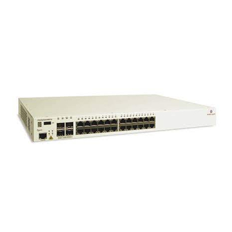
Page 34: Omniswitch 6400-48
“LED Status Indicators” on page 2-20 for LED status information. Console Port RS-232 console port with an RJ-45 connector. Provides access to the CLI for configuration and management. SFP Combo Port LEDs Provides link and traffic status. Refer to “LED Status Indicators” on page 2-20 for LED status information. -
Page 35: Omniswitch 6400-48 Rear Panel
OmniSwitch 6400 Series Chassis and Hardware Components OmniSwitch 6400 Series Chassis Configurations OmniSwitch 6400-48 Rear Panel Note. The figure shows a pre-production version of the chassis without product, safety, and compliance information labels. All production versions of the chassis have these labels. OS6400-48 Rear Panel... -
Page 36: Os6400-48 Specifications
Operating: 5% to 95% (non-condensing) Storage: 5% to 95% (non-condensing) Ambient Temperature Operating: 32º F to 113º F (0 ºC to 45 ºC) Storage: 14º F to 158º F (-10 ºC to 70 ºC) Altitude Operating: Up to 10,000 ft. (3048 m) Storage: Up to 40,000 ft. -
Page 37: Omniswitch 6400-P48 Front Panel
“LED Status Indicators” on page 2-20 for LED status information. Console Port RS-232 console port with an RJ-45 connector. Provides access to the CLI for configuration and management. SFP Combo Port LEDs Provides link and traffic status. Refer to “LED Status Indicators” on page 2-20 for LED status information. -
Page 38: Omniswitch 6400 Series Hardware Users Guide July 2010
Note . The rear panel of the OS6400-P48 contains three DB-25 power supply connectors for connecting external 360W and 510W power supplies. One of the connectors is labeled 'Primary PS1' and two of the connectors are labeled 'Backup PS2'. The primary power supply must be connected to the 'Primary PS1' connector. -
Page 39: Os6400-P48 Specifications
Operating: 5% to 95% (non-condensing) Storage: 5% to 95% (non-condensing) Ambient Temperature Operating: 32º F to 113º F (0 ºC to 45 ºC) Storage: 14º F to 158º F (-10 ºC to 70 ºC) Altitude Operating: Up to 10,000 ft. (3048 m) Storage: Up to 40,000 ft. -
Page 40: Led Status Indicators
LED Status Indicators OmniSwitch 6400 Series Chassis and Hardware Components LED Status Indicators State Description Solid Green System software is operational. Solid Amber Hardware or System failure. Blinking Green Normal Diagnostics. Blinking Amber Switch operational but auto- configuration not successful. -
Page 41: Omniswitch 6400 Series Power Supplies
OmniSwitch 6400 Series Chassis and Hardware Components OmniSwitch 6400 Series Power Supplies OmniSwitch 6400 Series Power Supplies OmniSwitch 6400 Series switches support the following power supplies: • PS-510W-AC Power Supply (see “PS-510W-AC Power Supply” on page 2-22) • PS-510W-AC-E Power Supply (see “PS-510W-AC-E Power Supply”... -
Page 42: Ps-510W-Ac Power Supply
OmniSwitch 6400 Series Power Supplies OmniSwitch 6400 Series Chassis and Hardware Components PS-510W-AC Power Supply The PS-510W-AC Power Supply provides system and PoE power and can be installed as either a primary or redundant power supply. 510W AC System/PoE Power Supply... - Page 43 OmniSwitch 6400 Series Chassis and Hardware Components OmniSwitch 6400 Series Power Supplies PS-510W-AC-E Power Supply The PS-510W-AC-E Power Supply provides enhanced system and PoE power and can be installed as either a primary or redundant power supply. 510W AC Enhanced System/PoE Power Supply...
-
Page 44: Ps-360W-Ac Power Supply
OmniSwitch 6400 Series Power Supplies OmniSwitch 6400 Series Chassis and Hardware Components PS-360W-AC Power Supply The PS-360W-AC Power Supply provides system and PoE and can be installed as either a primary or redundant power supply. 360W AC System/PoE Power Supply... - Page 45 OmniSwitch 6400 Series Chassis and Hardware Components OmniSwitch 6400 Series Power Supplies PS-360W-AC-E Power Supply The PS-360W-AC-E Power Supply provides enhanced system and PoE and can be installed as either a primary or redundant power supply. 360W Enhanced AC System/PoE Power Supply...
-
Page 46: Ps-126W-Ac Power Supply
OmniSwitch 6400 Series Power Supplies OmniSwitch 6400 Series Chassis and Hardware Components PS-126W-AC Power Supply The PS-126W-AC Power Supply provides system power and can be installed as a redundant system power supply. 126W AC System Power Supply P/S Component Description... -
Page 47: Ps-120W-Dc Power Supply
OmniSwitch 6400 Series Chassis and Hardware Components OmniSwitch 6400 Series Power Supplies PS-120W-DC Power Supply The PS-120W-DC Power Supply provides full system power and can be installed as a redundant system power supply. 120W -48VDC System Power Supply P/S Component... -
Page 48: Ac Internal Power Supply
12.0 VDC (typical) Output Current 10.8 A (maximum) 126W AC Internal System Power Supply 120W DC Internal Power Supply The 120W DC Internal Power Supply provides full system power. P/S Component Description Model 120W DC Internal Power Supply Provides Primary System Power... -
Page 49: Power Supply Shelf
OmniSwitch 6400 Series Power Supplies Power Supply Shelf Alcatel-Lucent requires the use of the power supply shelf when connecting power supplies. The shelf can be attached directly to the back of the chassis or rack mounted. OS6400 Power Supply Shelf... -
Page 50: Ac Power Cords
OmniSwitch 6400 Series Chassis and Hardware Components AC Power Cords Since the power cord is the switch’s only disconnect device, it should be plugged into an easily accessible outlet. In the event that your power cord is lost or damaged, refer to the specifications below. -
Page 51: Dc Power Specifications
The Branch Circuit Overcurrent Protection must be rated a Maximum of 15A. • Use 12AWG solid conductors only. • A readily accessible disconnect device that is suitably approved and rated shall be incorporated in the field wiring. Black MIN 1 TURN PER 1.5 HALF TURN PER .75... -
Page 52: Console Port
OmniSwitch 6400 Series Chassis and Hardware Components Console Port The console port, located on the chassis front panel, provides a console connection to the switch and is required when logging into the switch for the first time. By default, this RJ-45 connector provides an RS- 232 DTE console connection. - Page 53 If you use the commit system command only, changes will not be saved to the switch’s boot.params file and will be lost if the switch is rebooted. To save changes to the boot.params file, refer to step 7. Return to the CLI prompt by entering exit at the boot prompt.
-
Page 54: Port Pinouts
Gigabit Ethernet Port – RJ-45 Pinout Pin Number Description BI_DB+ BI_DB- BI_DA+ BI_DD+ BI_DD- BI_DA- BI_DC+ BI_DC- 10/100/1000 Mbps Power over Ethernet Port – RJ-45 Pinout Pin Number Description RX+ (-VDC) RX- (-VDC) TX+ (+VDC) not used not used TX- (+VDC) not used not used... -
Page 55: Rj-45 Console Port - Connector Pinout
OmniSwitch 6400 Series Chassis and Hardware Components Console Port RJ-45 Console Port – Connector Pinout Pin Number Signals as DTE Console Port Ground Ground OmniSwitch 6400 Series Hardware Users Guide July 2010 page 2-35... - Page 56 Console Port OmniSwitch 6400 Series Chassis and Hardware Components page 2-36 OmniSwitch 6400 Series Hardware Users Guide July 2010...
-
Page 57: Chapter 3 Mounting Os6400 Switches
General Mounting Recommendations Be sure that your switch is placed in a well-ventilated, static-free environment. Always allow adequate clearance at the front, rear, top, and sides of the switch. Refer the table below for detailed information on recommended chassis clearances. -
Page 58: Elevated Operating Ambient Temperatures
(Tma) specified by the manufacturer. Reduced Air Flow Installation of the equipment in a rack should be such that the amount of air flow required for safe operation of the equipment is not compromised. Mechanical Loading Mounting of the equipment in the rack should be such that a hazardous condition is not achieved due to uneven mechanical loading. -
Page 59: Airflow Recommendations
Airflow Recommendations Airflow Recommendations The OmniSwitch 6400 draws air from intake vents located in the left chassis panel and exhausts air via fan vents located in the right chassis panel. For each switch, air is directed horizontally through the chassis, where it passes over the circuit board and provides necessary cooling for internal components. -
Page 60: Fan Speed Control
100% Full <= 36 High Note: The fan will never be turned off completely. At it’s lowest setting it will always be running at the the Very Low speed setting (15%). page 3-4 OmniSwitch 6400 Series Hardware Users Guide July 2010... -
Page 61: Installation Overview
3-1. • Be sure that you have placed the chassis within reach of all the required AC or DC power sources. • If you are placing multiple switches in a stacked configuration Be sure to maintain adequate clearance at the front, rear, left, and right side of all switches (see page 3-1). -
Page 62: Tabletop Installation
Alcatel-Lucent). (The table mount flanges also provide rubber feet to protect the table surface.) If this kit is to used, orient the table mounting brackets so that the rubber bumper faces down and attach the brackets to both the left and right side of the switch using the attachment screws removed at step (refer to illustration below). -
Page 63: Next Steps
Mounting OS6400 Switches Tabletop Installation If the table mount flange kit is being used, install the table mount brackets to the rear portion of the chassis. Mount the switch assembly on the table by inserting attachment screws through the flat portion of the mounting brackets and into the mounting surface. -
Page 64: Rack-Mount Installation
To prevent a rack from becoming top heavy, it is recommended that you install heavier equipment at the bottom of the rack, whenever possible. • If you are installing the switch on a relay rack, be sure to install and secure the rack per the rack manu- facturer’s specifications. •... -
Page 65: Next Steps
Mounting OS6400 Switches Rack-Mount Installation Once the holes are aligned, insert a rack mount screw (not provided) through the bottom hole of each flange. Tighten both screws until they are secure. Attaching the Switch to the Rack Note. Be sure to install the screws in the bottom hole of each flange, as shown, before proceeding. -
Page 66: Setting Up A Stacked Configuration
Mounting OS6400 Switches Setting Up a Stacked Configuration Rack Mounting Stacked Configurations Prior to setting up and cabling the stacked configuration, be sure that all switches are in place and installed according to the instructions beginning on page (table mount configuration) or (rack mount config- uration). -
Page 67: Cabling Steps
End View of Stacking Cable Connector Starting from the top of the stack, insert one end of the stacking cable into either stacking port A or stacking port B. The stacking port (A or B) depends on your preferred cabling pattern. Be sure that cable connector is completely inserted and fully seated in the chassis. - Page 68 Mounting OS6400 Switches To provide added resiliency and redundancy, you must install the redundant stacking cable to connect the top switch in the stack to the bottom switch. Connect the redundant cable now. Refer to the diagram below for more information:...
-
Page 69: Installing Power Supplies
Connecting a Power Supply to the Chassis Follow the steps below to connect a power supply directly (i.e., without a cable) to the rear of an OmniSwitch 6400 Series chassis. Note. For information on rack mounting power supplies and connecting the power supply via a connector cable, refer to “Rack Mounting Power Supplies”... -
Page 70: Next Steps
Carefully slide the power supply against the back of the chassis until the power connectors securely connect. Verify that the captive screw for the power supply is aligned with the threaded hole in the power supply shelf. Secure the power supply to the power supply shelf by tightening the captive screw. -
Page 71: Rack Mounting Power Supplies
Be sure to tighten each of the screws firmly using a Phillips screwdriver. Attaching a Rack-Mount Flange Carefully slide the power supply on to the power shelf and secure the power supply to the shelf using the captive screws. - Page 72 Rack Mounting Power Supplies Mounting OS6400 Switches Note. A single 510W power supply or up to two of any other power supply types can be attached to a power supply shelf. After the rack-mount flanges and the power supply are secured to the shelf, mark the holes on the rack where the shelf is to be installed.
- Page 73 Mounting OS6400 Switches Rack Mounting Power Supplies Note. The diagrams below show examples of mounting the switch and power supplies in both a 2U and 3U scenario. Depending on the switch model, power supplies, and rack mounting options the actual mounting options will vary.
-
Page 74: Next Steps
Rack Mounting Power Supplies Mounting OS6400 Switches You can also attach the power supplies to the back of an OmniSwitch 6400 Series chassis directly as well as using cables at the same time, as shown in the diagram below. 1 7 . 6... -
Page 75: Connecting Chassis To Power Source
Connecting Chassis to Power Source AC Power Supply Connections Since the power cord is the switch’s only disconnect device, it should be plugged into an easily accessible outlet. In the event that your power cord is lost or damaged, refer to the specifications below. -
Page 76: Dc Power Supply Connections
HALF TURN PER .75 Twisted pair wire (red and black) for a DC power supply Note. Refer to the wiring diagram for information on connecting the DC power supply to a DC power source. Connecting to a DC Power Source The DC power supply on your switch contains a power connector with three (3) square slots for connect- ing the positive, negative, and ground wires from a DC power source. -
Page 77: Installing Dc Power Source Wire Leads
Opening Connector for Ground Wire Insert the ground wire lead into the slot. The lead you insert must match the lead attached to the DC power source. Warning. You must plug DC wire leads into the correct holes in the DC power connector. Use the labels above the DC power connector as a guide to positive, negative, and ground connections. - Page 78 Tighten the clamp by tightening the screw above the slot into which you inserted the wire lead. The wire lead should be securely attached inside the connector. You should be able to pull on the wire and not dislodge it.
-
Page 79: Hot-Swapping Power Supplies
Carefully slide the power supply out of the power supply shelf and set aside. Directly Connected Power Supply Carefully slide the new power supply onto the shelf and against the back of the chassis until the power connector securely connects Tighten the captive screw for the new power supply to the power supply shelf. -
Page 80: Hot-Swapping A Rack Mounted Power Supply
Carefully slide the power supply out of the power supply shelf and set aside. Rack-Mounted Power Supplies Carefully slide the new power supply on to the power supply shelf and secure the power supply to the shelf using the captive screw. -
Page 81: Booting Omniswitch 6400 Series Switches
The switch immediately begins the boot process. Allow a few moments for the switch to boot completely, then verify the status of all LEDs on the switch’s front panel. A successful boot for a stand-alone switch displays the following LED states:... -
Page 82: Chapter 4 Booting Omniswitch 6400 Series Switches
“OmniSwitch 6400 Series Chassis and Hardware Components” on page 2-1. To boot the stack, plug the power cord (provided) into the power connector socket at the rear panel of each switch in the stack. Next, plug all power cords, in rapid succession, into easily-accessible power sources, such as grounded AC outlets or an Uninterruptible Power Supply (UPS). -
Page 83: Monitoring The Chassis
OmniSwitch CLI Reference Guide for detailed information on all management and monitoring commands used with the OmniSwitch 6400 Series switch. Checking the Overall Chassis Status To check the overall status of a chassis, including the chassis type, and current administrative and opera- tional status, use the show chassis command. -
Page 84: Checking The Fan Status
Status -------+---+----------- Running Running For a complete list of output definitions for this command, refer to the OmniSwitch CLI Reference Guide. Checking the Power Supply Status For information on checking power supplies for OmniSwitch 6400 Series switches, refer to show power. -
Page 85: Managing Power Over Ethernet (Poe)
PoE, but are directly related to the feature: • PD refers to any attached device that uses a PoE data cable as its only source of power. Examples include access points, such as IP telephones, Ethernet hubs, wireless LAN stations, etc. -
Page 86: In This Chapter
Note. You can also monitor all chassis components and manage many chassis features, including Power over Ethernet, with WebView, Alcatel-Lucent’s embedded web-based device management application. WebView is an interactive and easy-to-use GUI that can be launched from the OmniVista or a web browser. Please refer to WebView’s Online Documentation for more information. -
Page 87: Power Over Ethernet Specifications
Managing Power over Ethernet (PoE) Power over Ethernet Specifications Power over Ethernet Specifications The table below lists general specifications for Alcatel-Lucent’s Power over Ethernet support. For more detailed power supply and Power Source Equipment (PSE) specifications, refer to Chapter 2, “OmniSwitch 6400 Series Chassis and Hardware Components.”... -
Page 88: Viewing Poe Power Supply Status
Viewing PoE Power Supply Status Managing Power over Ethernet (PoE) Viewing PoE Power Supply Status To view the current status of power supplies installed in the backup power supply, use the show power command, as shown below: -> show power... -
Page 89: Configuring Power Over Ethernet Parameters
OmniSwitch CLI Reference Guide. Note. PoE units support two different power supplies as noted above. If unlike power supplies are mixed or if an unsupported power supply (such as a 120W power supply) is used, a console message and a trap are generated. -
Page 90: Configuring The Total Power Available To A Port
Like the maximum port power allowance, the system software also provides a maximum slot-wide power allowance. Each slot is authorized by the system software to use up to default value of Watts, as noted in the specifications table, to power all devices connected to it depending on which power supply is used. -
Page 91: Setting Port Priority Levels
-> lanpower 1 maxpower 80 reduces the power allowance of the slot 1 to 80 watts. This value is now the maximum amount of power the slot can use to power all attached devices (until the value is modified by the user). -
Page 92: Setting The Capacitor Detection Method
For example, to disable the capacitor detection method on the switch with slot number 1, enter: -> lanpower capacitor-detection 1 disable Note. The capacitive detection method should only be enabled to support legacy IP phones. This feature is not compatible with IEEE specification 802.3af. Please contact your Alcatel-Lucent sales engineer or Customer Support representative to find out which Alcatel-Lucent IP phones models need capacitive detection enabled. -
Page 93: Understanding Priority Disconnect
PoE power budget for an additional device. For example, if there are only 2 watts available in the current PoE power budget and a user plugs a 3.5W powered device into a PoE port, the system software must determine whether the device will be powered on. -
Page 94: Priority Disconnect Is Enabled; Same Priority Level On All Pd
When a PD is being connected to a port with the same priority level as all other in the slot, the physical port number is used to determine whether the incoming PD will be granted or denied power. Lower- numbered receive higher priority than higher-numbered. -
Page 95: Priority Disconnect Is Disabled
Note. Priority disconnect examples are applicable only when there is inadequate power remaining to power an incoming device. When priority disconnect is disabled, power will be denied to any incoming PD, regardless of its port priority status (i.e., low, high, and critical) or physical port number (i.e., 1–24). -
Page 96: Monitoring Power Over Ethernet Via Cli
Amount of power budget remaining for PoE modules • Total amount of power remaining that for additional switch functions When entering the show lanpower command, you must include a valid slot number in the command line syntax. For example: -> show lanpower 1... - Page 97 410 Watts Total Power Budget Remaining 410 Watts Total Power Budget Available 1 Power Supplies Available Note. For detailed information on show lanpower command output, refer to the OmniSwitch CLI Refer- ence Guide. OmniSwitch 6400 Series Hardware Users Guide July 2010...
- Page 98 Monitoring Power over Ethernet via CLI Managing Power over Ethernet (PoE) page 5-14 OmniSwitch 6400 Series Hardware Users Guide July 2010...
-
Page 99: Chapter 6 Managing Omniswitch 6400 Series Stacks
In addition to their working as individual stand-alone switches, OmniSwitch 6400 Series switches can also be linked together to work as a single virtual chassis known as a stack. With stacks, users can easily expand their switching capacity simply by adding additional switches to the stack. In addition, stacks provide enhanced resiliency and redundancy features. -
Page 100: In This Chapter
Note. You can also manage and monitor OmniSwitch 6400 Series stacks through WebView, Alcatel-Lucent’s embedded web-based device management application. WebView is an interactive and easy-to-use GUI that can be launched from OmniVista or a web browser. Please refer to WebView’s online documentation for more information. -
Page 101: Omniswitch 6400 Series Stack Overview
For example, a user can start with a stack composed of two switches and add up to six additional switches to that stack as network demands increase over time. - Page 102 Roles Within the Stack Managing OmniSwitch 6400 Series Stacks Important Note. For management module redundancy to work effectively, the software on all switches operating in the stack must be synchronized at all times. Refer to “Synchronizing Switches in a Stack” on page 6-35 for more information.
- Page 103 Offline offline (e.g., powered off or rebooted by the user). Secondary The switch operating as the secondary management module immediately takes over the primary role. It is at this point Offline essentially operating as a stand-alone switch. Primary If the switch that previously failed or was taken offline...
-
Page 104: Primary Management Module Selection
By default, the primary management role will be given to the switch with the lowest chassis MAC address. However, for this to occur, all switches in the stack must be booted within 15 seconds of each other. In addition, switches in the stack must have no preconfigured slot information. Because of these two condi- tions, the MAC address method for selecting the primary module usually occurs with new “out of the box”... - Page 105 1, it is not a requirement. In other words, a stack of four switches can have slot assignments 3, 4, 5, and 6. However, it is important that each element in a stack is assigned a unique slot number.
- Page 106 A user can override both the MAC address and saved slot methods for determining a stack’s primary management module. This is done by controlling the uptime of switches in the stack. If all elements of a stack are powered off, the user can force a particular switch to become primary by powering on that switch and waiting a minimum of 15 seconds before powering on any other switches.
-
Page 107: Secondary Management Module Selection
Using the Stacking Connection to the Primary Switch By default, the switch that is connected to the primary switch’s stacking port A is automatically assigned the secondary management role. This applies to stacks on which there is no preassigned slot information—... - Page 108 For example, if a stack of four switches is booted and the preassigned slot values for each switch are 1, 2, 3, and 4, the switch with the slot value of 2 is assigned the secondary role.
-
Page 109: Idle Module Role
Roles Within the Stack Idle Module Role Switches that are not assigned either the primary or secondary role in a stack are, by default, assigned the role of idle modules. These idle modules operate similarly to Network Interface (NI) modules in a chassis- based switch such as the OmniSwitch 9700/9800. -
Page 110: Pass-Through Mode
StackB In this example, note that both slots 2 and 3 have a saved slot value of 2. If this stack is rebooted, a dupli- cate slot error will occur and the switch with the lower MAC address will be given the secondary manage- ment role. -
Page 111: Recovering From Pass-Through Mode (Duplicate Slot Numbers)
PASS-THRU; also, the state displays DUP-SLOT, or duplicate slot number. This can be further verified by looking down the saved slot column in the table. Note that slot 2, operating in the secondary management role, has a saved slot value of 2. Slot 1001, operating in pass-through, also has a saved slot value of 2. - Page 112 (leaving the primary and secondary roles to slots 1 and 2, respectively). There are now no duplicate numbers in the stack and all elements are operating normally: ->...
- Page 113 When all elements in the stack come up following the reboot, there are no longer any duplicate slot numbers in the stack. In addition, the stack topology is more orderly and, as a result, easier to manage: -> show stack topology...
-
Page 114: Stack Redundancy And Failover
The figure below shows how the redundant connection between the top and bottom switches in the stack ensures that data will continue to flow throughout the stack, even in the event of a connection failure at one of the stacking cables. -
Page 115: Checking Redundant Stacking Cable Status
Redundant stacking cables provide a form of dual redundancy. As shown in the figure above, the redun- dant cable allows traffic to flow in the event of a stacking link failure. The redundant cable also provides failover if a switch goes down within the stack. Traffic continues to flow between the modules that remain... -
Page 116: Slot Numbering
Managing OmniSwitch 6400 Series Stacks Slot Numbering For a stack of OmniSwitch 6400 Series switches to operate as a virtual chassis, each module in the stack must be assigned a unique slot number. To view the current slot assignments for a stack, use the... -
Page 117: Dynamic Slot Number Assignment
Dynamic Slot Number Assignment Dynamic slot number assignment occurs when there are no boot.slot.cfg files present in the switches’ /flash directories. This is the case for new, “out of the box,” switches that have not been previously booted. When a brand new stack (or stack with no boot.slot.cfg files) is booted, the system software automati- cally detects the module with the lowest MAC address. - Page 118 Managing OmniSwitch 6400 Series Stacks If the switch with the lowest MAC address happens to be the bottom-most module in the stack, slot numbering will not resume from the top of the stack. Instead, the system software will select the second- ary module using the standard method (i.e., the switch connected to the primary’s stacking port A), then...
-
Page 119: Manual Slot Number Assignment
For this example, the primary and second- ary roles will be assigned to the top of the stack. This is accomplished by entering the following commands: ->... -
Page 120: Reverting To The Dynamic Slot Numbering Model
Slot 5 - Idle Slot 6 - Idle Slot 7 - Idle Slot 8 - Idle Note: The stack set slot command can also be used to manually correct duplicate saved slot assignments within the stack topology. Refer to pages 6-12 through 6-14 for detailed information. -
Page 121: Hot-Swapping Modules In A Stack
Note. If it is preferable to add a switch with an existing boot.slot.cfg file to a stack, be sure that the saved slot number of the incoming switch is not already assigned to a switch operating in the stack. -
Page 122: Merging Stacks
Merging stacks involves connecting two or more operational stacks and attempting to reboot them as a single virtual chassis. In most cases, errors will result. To merge stacks without causing errors, select one stack that is to remain up and running and then add modules from the other stack(s) by following the steps below: Make sure all switches are running the same software version. -
Page 123: Reloading Switches
Reloading Switches Reloading Switches Reloading is essentially a soft boot of a switch. Users can reload stacked modules operating in any role— i.e., primary, secondary, idle, and pass-through. Refer to the sections below for more information. Reloading the Primary Management Module If the switch with the primary management role is reloaded, the switch with the secondary role automati- cally takes over primary management functions. - Page 124 Reloading Switches Managing OmniSwitch 6400 Series Stacks If there are only two switches in the stack, the switch that was reloaded (the former primary) assumes the secondary role when it comes back up. In this stack of two OmniSwitch 6400 Series switches, the slot 1 Primary - Slot 1 switch is the primary management module.
-
Page 125: Reloading The Secondary Management Module
Reloading Switches Reloading the Secondary Management Module If the switch with secondary management role is reloaded, the idle switch with the lowest slot number will automatically assume the secondary role. The reloaded switch (the former secondary) will assume an idle role when it comes back up. - Page 126 Reloading Switches Managing OmniSwitch 6400 Series Stacks If there are only two switches in the stack, the switch that was reloaded (the former secondary) resumes the secondary role when it comes back up. In this stack of two OmniSwitch 6400 Series switches, the slot 1 Primary - Slot 1 switch is the primary management module.
-
Page 127: Reloading Switches With Idle Roles
After reloading a switch operating in an idle role, the switch resumes idle status when it comes back up, despite its saved slot number. In other words, if an idle switch with a saved slot number of 1 is reloaded, it resumes its previous idle role. -
Page 128: Reloading All Switches In A Stack
Managing OmniSwitch 6400 Series Stacks Reloading All Switches in a Stack Reloading all switches in the stack is essentially a full reboot of the virtual chassis. This can be useful in restoring a stack’s previously configured topology—i.e., the stack’s saved slot numbers and management roles. - Page 129 Two or More Switches Have Duplicate Slot Information If a full stack reboot is issued and the same slot number is found in the boot.slot.cfg file of two or more switches, the switch with the lowest MAC address is allowed to come up and operate normally. Mean- while, any other switches with the duplicate slot number come up in pass-through mode.
-
Page 130: Avoiding Split Stacks
Reloading Switches Managing OmniSwitch 6400 Series Stacks Avoiding Split Stacks The term “splitting” a stack refers to the creation of isolated modules within the virtual chassis. A split stack can result from the following conditions: • Two or more non-adjacent switches are reloaded simultaneously •... -
Page 131: Changing The Secondary Module To Primary
OmniSwitch 6400 Series stacks allow users to manually force the secondary switch to assume the primary management role. This is referred to as “takeover.” The behavior of a takeover is similar to that of reload- ing the primary management module (see page 6-25). - Page 132 Changing the Secondary Module to Primary Managing OmniSwitch 6400 Series Stacks If there are only two switches in the stack, the former primary switch resumes the secondary role when it comes back up following the takeover. In this stack of two OmniSwitch 6400 Series switches, the slot 1 Primary - Slot 1 switch is the primary management module.
-
Page 133: Synchronizing Switches In A Stack
The synchronization process ensures that the contents of these directories match exactly for all switches across the stack. This can be especially useful after new software has been loaded to the primary manage- ment module. Further, synchronization prevents any switch from assuming a management role within the stack with incorrect or outdated software or configuration files. -
Page 134: Monitoring The Stack
Managing OmniSwitch 6400 Series Stacks Monitoring the Stack As shown in the previous sections, monitoring the current status and operation of all elements in a stack can help users avoid unexpected stack conditions. The table below includes CLI commands that are useful in monitoring stack conditions. -
Page 135: Cli Commands Supported On Both Primary And Secondary Management Modules
Although most CLI commands are executed when logged into the switch with the primary management role, there is a group of commands that is supported when logged in to either the primary or secondary management module. For a list of these commands, refer to the tables below. - Page 136 Monitoring the Stack Managing OmniSwitch 6400 Series Stacks page 6-38 OmniSwitch 6400 Series Hardware Users Guide July 2010...
-
Page 137: Regulatory Compliance And Safety Information
A Regulatory Compliance and Safety Information This appendix provides information on regulatory agency compliance and safety for the OmniSwitch 6400 Series switches. Declaration of Conformity: CE Mark This equipment is in compliance with the essential requirements and other provisions of Directive 73/23/EEC and 89/336/EEC as amended by Directive 93/68/EEC. -
Page 138: China Rohs: Hazardous Substance Table
This table shows where these substances may be found in the supply chain of Alcatel-Lucent electronic information products, as of the date of sale of the enclosed product. Note that some of the component types listed above may or may not be a part of the enclosed product. - Page 139 Regulatory Compliance and Safety Information China RoHS: Hazardous Substance Table Products are packaged using one or more of the following packaging materials: Corrugated Cardboard Corrugated Fiberboard Low-Density Polyethylene OmniSwitch 6400 Series Hardware Users Guide July 2010 page A-3...
-
Page 140: Waste Electrical And Electronic Equipment (Weee) Statement
Waste Electrical and Electronic Equipment (WEEE) Statement The product at end of life is subject to separate collection and treatment in the EU Member States, Norway and Switzerland and therefore marked with the symbol: Treatment applied at end of life of the product in these countries shall comply with the applicable national laws implementing directive 2002/96EC on waste electrical and electronic equipment (WEEE). -
Page 141: Standards Compliance
• CDRH Laser • GOST Russia EMI/EMC Standards • FCC Part 15 (CFR 47) Class A. (Note: Class A with UTP cables.) • EN 55022: 1995 (Emission Standard) • AS/NZS 3548 Class A. (Note: Class A with UTP cables.) •... -
Page 142: Fcc Class A, Part 15
FCC Class A, Part 15 This equipment has been tested and found to comply with the limits for Class A digital device pursuant to Part 15 of the FCC Rules.These limits are designed to provide reasonable protection against harmful inter- ference when the equipment is operated in a commercial environment.This equipment generates, uses, and... -
Page 143: Vcci
Standards Compliance VCCI This is a Class A product based on the standard of the Voluntary Control Council for Interference by Information Technology Equipment (VCCI). If this equipment is used in a domestic environment, radio disturbance may arise. When such trouble occurs, the user may be required to take corrective actions Class A Warning for Taiwan and Other Chinese Markets This is a Class A Information Product. -
Page 144: Translated Safety Warnings
Two people are required when lifting the chassis. Due to its weight, lifting the chassis unassisted can cause personal injury. Also be sure to bend your knees and keep your back straight when assisting with the lift- ing of the chassis. -
Page 145: Installation Warning
Blicken Sie nicht in die Öffnungen und installieren Sie unverzüglich die Abdeckungen über den Glasfaseranschlüssen. Español: Debido a que la apertura del puerto puede emitir radiación invisible cuando no hay un cable de fibra conectado, procurar no mirar directamente a las aperturas para no exponerse a la radiación. -
Page 146: Lithium Battery Warning
Lever det brugte batteri tilbage tilleverandoren. Operating Voltage Warning To reduce the risk of electrical shock, keep your hands and fingers out of power supply bays and do not touch the backplane while the switch is operating. -
Page 147: Power Disconnection Warning
Translated Safety Warnings Power Disconnection Warning Your switch is equipped with multiple power supplies. To reduce the risk of electrical shock, be sure to disconnect all power connections before servicing or moving the unit. Français: Il se peut que cette unité soit équipée de plusieurs raccordements d'alimentation. Pour supprimer tout courant électrique de l'unité, tous les cordons d'alimentation doivent être débranchés. -
Page 148: Read Important Safety Information Warning
Zugang hat. Español: Este equipo se debe instalar en un sitio con acceso restrinjido. Un sitio con el acceso restrinjido es uno seguro y con acceso limitado al personal de servicio que tiene una clave especial u otros medios de seguridad. -
Page 149: Wrist Strap Warning
For this purpose, Alcatel-Lucent provides a ground- ing wrist strap and a grounding lug located near the top-right of the chassis. For the grounding wrist strap to be effective in eliminating ESD, the power supplies must be installed in the chassis and plugged into grounded AC outlets. -
Page 150: Instrucciones De Seguridad En Español
Advertencia sobre el levantamiento del chasis Se requieren dos personas para levantar el chasis. Debido a su peso, la elevación del chasis sin ayuda puede causar daños corporales. También es seguro doblar sus rodillas y guardar su espalda derecho al ayudar a levantar el chasis. -
Page 151: Advertencia Sobre Una Apropiada Conexión A Tierra
Este equipo se debe instalar en una ubicación que restrinja el acceso. Una ubicación con acceso restring- ido es una donde está seguro y limitado el acceso al personal de servicio que tiene un clave especial, u otros medios de la seguridad. - Page 152 Instrucciones de seguridad en español Regulatory Compliance and Safety Information page A-16 OmniSwitch 6400 Series Hardware Users Guide July 2010...
Need help?
Do you have a question about the OS6400-48 and is the answer not in the manual?
Questions and answers