Table of Contents
Advertisement
Advertisement
Table of Contents

Related Manuals for Alcatel OS6602-24


Summary of Contents for Alcatel OS6602-24
-
Page 1: Omniswitch 6600 Family
® OmniSwitch 6600 Family Getting Started Guide 060178-10, Rev. E March 2005... - Page 2 The features and specifications described in this guide are subject to change without notice. Copyright © 2005 by Alcatel Internetworking, Inc. All rights reserved. This document may not be reproduced in whole or in part without the express written permission of Alcatel Internetworking, Inc.
-
Page 3: Table Of Contents
OS6602-48 ......7 Features ........1 Items Included . - Page 4 Guidelines ....... . 27 ........41 Booting the Stack .
- Page 5 ....48 Online Help ....... 60 Boot and Image Files .
- Page 6 March 2005...
-
Page 7: Omniswitch 6600 Family
VLANs and bone or server. security. OmniSwitch 6600 Family switches also support wire- speed Layer 2 and Layer 3 switching, industry-based stan- dards, and a full array of reliability, redundancy and resiliency capabilities. March 2005 OmniSwitch 6600 Family... -
Page 8: Stacked Configurations
This provides a virtual chassis with a 10/100 or 100 capacity of up to 384 ports. Hardware-related Availability features include: Smart Continuous Switching •... -
Page 9: Chassis Types
48 10/100 Ethernet ports. The OS6648 can also be equipped 24 10/100 Ethernet ports. The OS6624 can also be equipped with up to four Gigabit Ethernet ports for connections to a with up to four Gigabit Ethernet ports for connections to a high speed backbone or server. -
Page 10: Omniswitch 6600-U24 (Os6600-U24)
The OS6600-U24 is a stackable edge/workgroup switch offer- The OS6600-U24 is a stackable edge/workgroup switch offer- ing 24 100 SFP Ethernet ports. The OS6600-U24 can also be ing 24 Power over Ethernet (PoE) 10/100 Ethernet ports. The equipped with up to four Gigabit Ethernet ports for connec- OS6600-P24 can also be equipped with up to four Gigabit tions to a high speed backbone or server. -
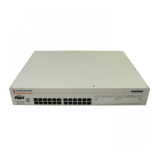
Page 11: Omniswitch 6602-24 (Os6602-24)
24 10/100 Ethernet ports. The OS6602-24 can also be 48 10/100 Ethernet ports. The OS6602-48 can also be equipped with up to two Gigabit Ethernet ports for connec- equipped with up to two Gigabit Ethernet ports for connec- tions to a high speed backbone or server. -
Page 12: Setting Up The Hardware
OmniSwitch 6600 Family switches have the following envi- With redundant AC, if a single circuit fails, the switch’s ronmental and airflow requirements: back up power supply (on a separate circuit) will likely be unaffected and can therefore continue operating. The installation site must maintain a temperature •... -
Page 13: Weight Considerations
96 lbs (36 Kgs). OS6624 OS6602-24 With a back up power supply installed, a single OS6624 weighs approximately 13.5 lbs (6.1 Kgs). Without a back up power supply installed, a single OS6602-24 weighs approximately 12 lbs (4.5 Kgs). -
Page 14: Optional Items
In order to greatly reduce exposure to electrostatic discharge (ESD) and physical damage, do OS6600-GNI-U2 or OS6600-GNI-C2 Gigabit Ethernet • not unpack these items until they are ready to be uplink modules installed. MiniGBIC-SX, MiniGBIC-LX, or MiniGBIC-LH-70 •... -
Page 15: Instructions
Setting Up the Switch Instructions Carefully cut the tape along the seam at the top of the Note. Due to their airflow and access requirements, box containing the chassis. OmniSwitch 6600 Family switches cannot be wall- mounted. Lift the box’s top flaps. Remove any smaller boxes or pouches that are enclosed and set them aside. -
Page 16: Installing The Switch On A Tabletop Or Bench
If you are placing multiple switches in a stacked configuration, carefully stack the remaining switches, one on top of the other. Up to eight switches may be stacked to form a single virtual chassis. Be sure to maintain adequate clearance at the front, rear, left, and right side of all switches. -
Page 17: Rack-Mounting The Switch
Alcatel does not provide rack-mount screws. Use the • Note. Do not turn on the power supplies at this time. You screws supplied by the rack vendor. will power on all switches later in the setup process. To prevent a rack from becoming top heavy, it is •... - Page 18 After the rack-mount flanges are secured to the chas- Note. Be sure to install the screws in the bottom hole of sis, mark the holes on the rack where the switch is to be each flange, as shown, before proceeding.
-
Page 19: Rack Mounting Stacked Configurations
For additional instructions on rack mounting a stacked config- Note. Do not turn on the power supply at this time. You uration, follow the steps below: will power on the switch later in the setup process. -
Page 20: Installing A Back Up Power Supply (Os6624, Os6648, Os6600-U24)
If the optional back up power supply was included with your order, install the power supply now by following the steps Note. Do not turn on the power supplies at this time. You below. The back up power supply bay is located at the will power on all switches later in the setup process. - Page 21 X COR E LA FAIR Continue sliding the power supply back until the front panel is flush with the rear panel of the chassis. Do not force the power supply into the bay. Otherwise you can damage the connectors. March 2005...
-
Page 22: Installing Uplink And Stacking Modules
OS6602-48 switches. grounded power source. Note. Do not turn on the power supply at this time. You will power on all supplies later in the setup process. Setting Up the Hardware March 2005... - Page 23 Set the cover panel and attachment screws aside. Important. Stacking modules can only be installed in the Holding the uplink or stacking module by the front far-right module slot.
-
Page 24: Installing Minigbic Connectors
Slide the module back until the backplane connector is inserted in the chassis backplane; the module’s front panel should be flush with the front of the chassis. Do not force Each OS6600-GNI-U2 uplink module supports up to two Mini the module into the slot. Otherwise you can damage the Gigabit Interface Converters (MiniGBICs). - Page 25 Holding the MiniGBIC by its sides, carefully slide it Push the MiniGBIC into the slot until it is completely into the desired MiniGBIC slot in the OS6600-GNI-U2 inserted and securely seated in the OS6600-GNI-U2 module, as shown. module, as shown.
-
Page 26: Installing Sfp Connectors (Os6600-U24 Only)
Installing SFP Connectors Holding the SFP by its sides, carefully slide it into the (OS6600-U24 Only) desired SFP slot (ports 1–24) on the OS6600-U24 module, as shown. The OS6600-U24 supports up to twenty-four 924) 100 Mbps Small Form-factor Pluggable (SFPs). These SFPs are pack- aged separately and therefore are not factory-installed. -
Page 27: Blank Cover Plates
These cover plates play an important role in chassis airflow and temperature management. They also protect the switch’s processor board and other sensitive internal switch compo- nents from physical damage by closing off a chassis that is not fully populated. Because they regulate airflow and help protect internal chassis components, blank cover plates should remain installed over empty module slots and power supply bays at all times. -
Page 28: Connections And Cabling
The console port, located on the chassis front panel, provides a serial connection to the switch and is required when logging Serial cable (OS6624 and OS6648) or RJ-45 (OS6600- into the switch for the first time. By default, this connector (a • U24, OS6600-P24, OS6602-24, OS6602-48) to the... -
Page 29: The Next Step
The Next Step If you are setting up a stand-alone OmniSwitch 6600 Family switch (i.e., a switch that is not a part of a stacked configura- tion), skip to “Booting Stand-Alone Switches” on page March 2005 Connections and Cabling... -
Page 30: Completing A Stacked Configuration
26 for one of many valid occur and the stack will be disabled. slot numbering possibilities. The top switch in the stack does not have to be desig- • nated as slot 1. Follow the steps beginning on page 25 to assign slot numbers for OmniSwitch 6600 Family switches. -
Page 31: Assigning Slot Numbers
Assigning Slot Numbers Power on a single switch in the stack. Do not power on any additional switches in the stack at this time. t c h n i S The slot number is displayed by the slot indicator LED located on the left side of the chassis front panel (refer to “OmniSwitch 6600 Status LEDs”... -
Page 32: Slot Numbering Example
• The top switch in the stack does not t c h n i S have to be designated as slot 1; for this example, the top switch has been designated slot number 4. • Because it has the lowest user-assigned slot number, switch number 3 will be given the stack’s primary management... -
Page 33: Connecting Cables To Stacking Modules
Port numbers are clearly marked on the chassis front • panel. to Stacking Modules Starting from the top of the stack, attach one end of a 30 cm stacking cable to a High Speed Serial Data Guidelines Connector (HSSDC) located on the switch’s stacking module, as shown. - Page 34 Attach the other end of the cable to a HSSDC connec- To provide added resiliency and redundancy, it is tor on the switch immediately below. Repeat this proce- strongly recommended that you install the optional one- dure until all switches in the stack are connected (see meter stacking cable to connect the top switch in the stack illustrations a, b, and c below).
-
Page 35: Booting The Stack
Move the on/off switch for the back up power supply to the on ( | ) position. Automatic Software Synchronization. In order to ensure... -
Page 36: Verifying Led Status
In other ondary or idle, this LED is off) words, if you assigned a switch in the stack as slot 1, this switch should have the primary role. Solid Green (if the switch is the secondary switch in a stack;... -
Page 37: Sec Led
The secondary role is given to the switch with the next-lowest number. To verify this, check the SEC LED on the front panel of the switch with the next-lowest assigned slot number. The SEC LED should be illuminated solid green. -
Page 38: Your First Login Session
Important. If you are using OmniSwitch 6600 Family switches in a stacked configuration, you must be When you first log in to the switch, you will be prompted for a connected to the console port of the stack’s primary login (i.e., user) name and password. During this first login switch. -
Page 39: Assigning An Ip Address To The Switch Or Stack
Remote sessions such as Telnet, FTP, and WebView require All Rights reserved. an IP address. The IP address for these session types serves as OmniSwitch(TM) is a trademark of Alcatel Internetwork- a destination point for the remote session. Therefore, before ing, Inc. -
Page 40: Assigning Ip Addresses To Switches In A Stacked Configuration
CLI prompt: tion, a duplicate IP addresses will exist on the network. Therefore, if a switch is to be pulled from a stack, it is -> aaa authentication default local recommended that the switch is given a unique IP address... -
Page 41: Unlocking Specified Session Types
4 concurrent sessions sions allowed New password settings are automatically saved in real time to the local user database; the user is not required to enter an Total sessions (Telnet, FTP, 13 concurrent sessions additional command in order to save the password informa- HTTP, console) tion. -
Page 42: Setting The System Time Zone
The switch’s default time zone is UTC (also referred to as Greenwich Mean Time). If you require a time zone that is specific to your region—or if you need to enable Daylight Savings Time (DST) on the switch—you can configure these settings via the... -
Page 43: Setting Optional System Information
An administrative contact is the person or department in Specifying the Switch’s Location charge of the switch. If a contact is specified, users can easily find the appropriate network administrator if they have ques- tions or comments about the switch. -
Page 44: Viewing Your Changes
The switch’s serial connection defaults are listed on page If you wish to modify the default serial connection settings (i.e., baud rate, parity, data bits, and stop bits), refer to the Saving Your Changes following steps. Once you have configured this basic switch information, save Note. - Page 45 Options include 7 and 8 (default). For example: You can also save your changes in real time to the switch’s running memory by entering commit system at Boot > boot serialwordsize 7 the boot prompt: Boot >...
- Page 46 This completes the initial setup process. Your OmniSwitch OmniSwitch 6600 Family switch is now ready for additional configuration and network operation. Refer to the following sections for more information on using your switch, as well as additional built-in features. Your First Login Session...
-
Page 47: Cli Basics
If you make a mistake while entering command syntax, the The following section provides basic information on CLI CLI provides clues about how to correct the error. Whenever a assistance features. For detailed information on the CLI, command error is entered, two indicators are displayed: including syntax conventions, usage rules, command docu- An Error message describing the type of error. -
Page 48: Command Line (?) Help
To change incorrect syntax with the Delete key, use the Left Arrow key to move the cursor to the left of the character to be Some command completion options may indicate user-defined deleted, then use the Delete key to remove characters to the information. -
Page 49: Inserting Characters
Up Arrow key at the prompt and the previous command will VLAN Management • display on your screen. You can execute the command again by pressing Enter, or you can edit it first by deleting or insert- ing characters. March 2005 CLI Basics... -
Page 50: Prefix Prompt
-> vlan 32 this case, show temperature) at the CLI prompt. To set the prompt back to the default arrow ( -> ), enter the following syntax, exactly as shown, at the prefix prompt: You can also recall the last command in the history list by entering two exclamation points ( !! ). -
Page 51: Command Logging
OmniSwitch 6600 Family switches provide command logging. created in the switch’s /flash directory. Once enabled, configu- This feature allows users to record up to 100 of the most recent ration commands entered on the command line will be commands entered via Telnet and console sessions. In addi- recorded to this file until command logging is disabled. -
Page 52: Common Cli Commands
Displays basic hardware and status information for a stand- The following table lists some basic CLI commands that will alone switch, or for all help you get acquainted with the CLI interface. Enter each switches installed in a stacked command exactly as shown. -
Page 53: Offline Configuring
You can apply a file to the switch immediately. You can also an ASCII-based text file. This is referred to as offline configur- schedule a file to be applied either at a specific date and time, ing. With offline configuring, CLI commands may be typed or after a specific amount of time has passed. -
Page 54: Files And Directories
/flash/certified directory and become part of the “last known In order to be read by the switch, the boot.params file must be good” software for the switch. placed in the /flash directory. If the file is deleted for any reason, a new boot.params file will be automatically gener-... -
Page 55: Boot.slot.cfg File
Hweb.img Provides support for the WebView software application. If you delete all copies of an image file, you will be required to contact Alcatel Customer Support for replacements. There- Hwebl2eth.img Provides WebView configuration of fore, it is recommended that you keep backup copies on your Layer 2 features. - Page 56 Hwebqos.img Provides WebView configuration of Quality of Service (QoS) features. Hwebadvrout.img Enables WebView configuration of Alcatel’s Advanced Routing. Optional. Hwebsecu.img Provides WebView configuration of enhanced security features for the switch. Files and Directories March 2005...
-
Page 57: Working And Certified Directories
Alcatel’s OmniSwitch 6600 Family switches are shipped with files are road-tested and considered valid and reliable for your 32 MB of flash memory. This memory is used to store files, network, they can be copied to the /flash/certified directory. including boot and image files, that are used for switch opera- tions. -
Page 58: How Can I Tell Which Directory The Switch Is Currently Using
/flash/certified directory. There- What happens when the switch boots? fore, verifying the current running directory is a key step any time you are configuring or monitoring the switch. During the boot process, the switch compares the contents of the /flash/working and /flash/certified directories. -
Page 59: Working And Certified Are Different
Yes. If its configuration and image files are known to be reli- able, you can override the default and initiate a reboot from the Working and Certified Are Different /flash/working directory. -
Page 60: Loading Software
.img files from the /flash/working directory. slightly for stand-alone and stacked OmniSwitch 6600 Family You can use the asterisk (*) wildcard to delete all .img configurations. Follow the steps that apply to your system. files at once. For example: ->... -
Page 61: Stacked Configurations
You can use the asterisk (*) wild- /flash/certified directory remains unchanged and available as card to delete all .img files at once. For example: a last known good version if an error should occur with the -> rm working/*.img new software. -
Page 62: Certifying Your New Software
/flash/working directory. After the newly-loaded software is considered tested and reli- able, it is important that you certify the new software by copy- Use the install command after the software files have ing it to the /flash/certified directory. -
Page 63: Using Webview
The switch can be configured and monitored using WebView, Alcatel’s Web-based device management tool. WebView soft- ware is pre-installed in the switch; you are not required to load In order to access WebView, the following image files must be additional software. -
Page 64: Logging In To Webview
Logging In to WebView Remember, if you have already changed the user name and password for your switch, be sure to use the new information. If you have not changed your user name or password, the Note. Before attempting to establish a WebView session, factory defaults are admin and switch, respectively. - Page 65 By providing quick, easy access to specific pages, site maps can reduce time spent searching through the WebView application. To access site maps, click the “Site Map” link included on each configuration group Home page, (e.g., Health). Main “Configuration Group”...
-
Page 66: Online Help
Context-specific Help password. If you have already changed the user name and button. password for your switch, be sure to use the new informa- tion. If you have not changed the user name and password, (In this case, for the VLAN the factory defaults are admin and switch, respectively. -
Page 67: Hardware Basics
Slot Selector Button 10BaseT or 100BaseTX. The ports use RJ-45 connectors. If you use a Gigabit Ethernet uplink module in this slot, The slot selector button, located directly the OS6624 must be used as a stand-alone switch. beneath the slot indicator LED, is used to... -
Page 68: Omniswitch 6600-U24 Front Panel
Ethernet uplink module. SFP-100-LC-SM, and SFP-100- Slot Selector Button MTRJ transceivers in any combina- If you use a Gigabit Ethernet uplink module in this slot, The slot selector button, located directly tion. the OS6600-U24 must be used as a stand-alone switch. -
Page 69: Omniswitch 6648 Front Panel
10BaseT or 100BaseTX. The ports Slot Selector Button use RJ-45 connectors. If you use a Gigabit Ethernet uplink module in this slot, The slot selector button, located directly the OS6648 must be used as a stand-alone switch. beneath the slot indicator LED, is used to... -
Page 70: Omniswitch 6600-P24 Front Panel
Slot Selector Button 10BaseT or 100BaseTX. The ports If you use a Gigabit Ethernet uplink module in this slot, The slot selector button, located directly use RJ-45 connectors. the OS6600-P24 must be used as a stand-alone switch. -
Page 71: Omniswitch 6602-24 Front Panel
This connector pro- vides a DCE console connection. Gigabit Ethernet Uplink Slots The OS6602-24 provides two MiniGBIC Gigabit Ethernet slots. OmniSwitch 6602-24 Stack CLASS 1 LASER PRODUCT Status and Slot Indicator LEDs... -
Page 72: Omniswitch 6602-48 Front Panel
This connector pro- vides a DCE console connection. Gigabit Ethernet Uplink Slots The OS6602-48 provides two MiniGBIC Gigabit Ethernet slots. OmniSwitch 6602-48 Stack CLASS 1 LASER PRODUCT Status and Slot Indicator LEDs... -
Page 73: Omniswitch 6600 Status Leds
Ethernet Port LEDs Each Ethernet port has a built-in corresponding LED. This Slot Indicator LED LED indicates the link and activity status for each Ethernet The slot indicator LED is manually configurable port. The LED displays green when a valid Ethernet cable and displays the switch’s current slot number in a... - Page 74 • comprehensive Alcatel user documentation, including the following manuals: Includes procedures for readying an individual switch for integration into a network. Topics include the soft- OmniSwitch 6600 Family Getting Started Guide ware directory architecture, image rollback protec- • tions, authenticated switch access, managing switch...
- Page 75 To load the CD and access the user documentation, refer to the instructions printed on the CD packaging. All documentation is in format and requires the Adobe Acrobat Reader program for viewing. Acrobat Reader free- ware is available at www.adobe.com.
- Page 76 Hardware Basics March 2005...
Need help?
Do you have a question about the OS6602-24 and is the answer not in the manual?
Questions and answers