Table of Contents
Advertisement
Quick Links
NuMaker-EVB-KM1M4B-TQFP64
NuMicro
Family
®
Based on Arm
Cortex
-M4
®
®
NuMaker-EVB-KM1M4B-TQFP64
User Manual
NuMicro
KM1M4B Series
®
The information described in this document is the exclusive intellectual property of
Nuvoton Technology Corporation and shall not be reproduced without permission from Nuvoton.
Nuvoton is providing this document only for reference purposes of NuMicro microcontroller based system
design. Nuvoton assumes no responsibility for errors or omissions.
All data and specifications are subject to change without notice.
For additional information or questions, please contact: Nuvoton Technology Corporation.
www.nuvoton.com
Mar. 29, 2024
Page 1 of 46
Rev 1.00
Advertisement
Table of Contents

Related Manuals for Nuvoton NuMicro KM1M4B Series


Summary of Contents for Nuvoton NuMicro KM1M4B Series
- Page 1 The information described in this document is the exclusive intellectual property of Nuvoton Technology Corporation and shall not be reproduced without permission from Nuvoton. Nuvoton is providing this document only for reference purposes of NuMicro microcontroller based system design. Nuvoton assumes no responsibility for errors or omissions.
-
Page 2: Table Of Contents
3.8.2 Status LEDs ........................23 4 QUICK START ....................24 4.1 Toolchains Supporting ....................24 4.2 Nuvoton Nu-Link Driver Installation ................24 4.3 BSP Firmware Download ................... 26 4.4 Hardware Setup ......................26 4.5 Find the Example Project ................... 28 4.6 Execute the Project under Toolchains .............. - Page 3 NuMaker-EVB-KM1M4B-TQFP64 5.3 PCB Placement ......................44 6 REVISION HISTORY ..................45 Mar. 29, 2024 Page 3 of 46 Rev 1.00...
- Page 4 NuMaker-EVB-KM1M4B-TQFP64 List of Figures Figure 1-1 NuMaker-EVB-KM1M4B-TQFP64 Evaluation Board ............. 7 Figure 3-1 Front View of NuMaker-EVB-KM1M4B-TQFP64 ............9 Figure 3-2 Rear View of NuMaker-EVB-KM1M4B-TQFP64 ............10 Figure 3-3 KM1M4BF54K Extension Connectors ................11 Figure 3-4 Arduino UNO Compatible Extension Connectors ............14 Figure 3-5 External Power Supply Sources on Nu-Link2-Me ............
- Page 5 NuMaker-EVB-KM1M4B-TQFP64 Figure 4-2 KM1M4BF54K Target Board Circuit ................43 Figure 4-3 Front Placement ......................44 Figure 4-4 Rear Placement ......................44 Mar. 29, 2024 Page 5 of 46 Rev 1.00...
- Page 6 NuMaker-EVB-KM1M4B-TQFP64 List of Tables Table 3-1 Extension Connectors ....................11 Table 3-2 KM1M4BF54K Full-pin Extension Connectors and GPIO Function List ......13 Table 3-3 Arduino UNO Extension Connectors and KM1M4BF54K Mapping GPIO List ....15 Table 3-4 Vin Power Source ......................16 Table 3-5 5 V Power Sources ......................
-
Page 7: Overview
NuMaker-EVB-KM1M4B-TQFP64 OVERVIEW The NuMaker-EVB-KM1M4B-TQFP64 is an evaluation board for Nuvoton KM1M4BF54K microcontroller. The NuMaker-EVB-KM1M4B-TQFP64 consists of two parts: a KM1M4BF54K target board and an on-board Nu-Link2-Me debugger and programmer. The NuMaker-EVB-KM1M4B-TQFP64 is designed for project evaluation, prototype development. The KM1M4BF54K target board is based on KM1M4BF54K. For the development flexibility, the KM1M4BF54K target board provides the extension connectors of KM1M4BF54K, the Arduino UNO compatible headers. -
Page 8: Features
NuMaker-EVB-KM1M4B-TQFP64 FEATURES KM1M4BF54K microcontroller with function compatible with: KM1M4BF54G – KM1M4BF54K – KM1M4BF54K extension connectors Arduino UNO compatible extension connectors Flexible board power supply: External V power connector – Arduino UNO compatible extension connector Vin – ICE USB connector on Nu-Link2-Me –... -
Page 9: Hardware Configuration
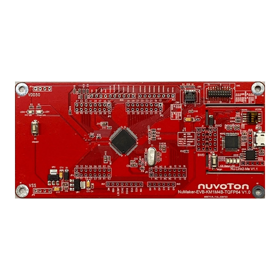
NuMaker-EVB-KM1M4B-TQFP64 HARDWARE CONFIGURATION Front View Figure 3-1 Front View of NuMaker-EVB-KM1M4B-TQFP64 Figure 3-1 shows the main components and connectors from the front side of NuMaker-EVB-KM1M4B- TQFP64. The following lists components and connectors from the front view: Target chip: KM1M4BF54K (U1) ... -
Page 10: Rear View
NuMaker-EVB-KM1M4B-TQFP64 Rear View Figure 3-2 Rear View of NuMaker-EVB-KM1M4B-TQFP64 Figure 3-2 shows the main components and connectors from the rear side of NuMaker-EVB-KM1M4B- TQFP64. The following lists components and connectors from the rear view: Nu-Link2-Me MCUVCC Power Switch (R6, R7) –... -
Page 11: Extension Connectors
NuMaker-EVB-KM1M4B-TQFP64 Extension Connectors Table 3-1 presents the extension connectors. Connector Description JP1, JP2, JP3 and JP4 Full pins extension connectors on the NuMaker-EVB-KM1M4B-TQFP64. NU1, NU2, NU3 and Arduino UNO compatible pins on the NuMaker-EVB-KM1M4B-TQFP64. Table 3-1 Extension Connectors 3.3.1 Pin Assignment for Extension Connectors The NuMaker-EVB-KM1M4B-TQFP64 provides the KM1M4BF54K onboard and extension connectors (JP1, JP2, JP3 and JP4). - Page 12 NuMaker-EVB-KM1M4B-TQFP64 KM1M4BF54K Header Pin No. Function JP1.1 P02/ADST0/SBO4/SBI4/SBCS1/TM15B/IRQ05 JP1.2 P00/ADST1/SBO4/SBI4/IRQ02 JP1.3 N.C. JP1.4 N.C. JP1.5 P01/ADST2/SBT4/GPWMST6/IRQ15/IRQ04 JP1.6 N.C. JP1.7 JP1.8 JP1.9 N.C. JP1.10 VDD50 JP1.11 PE2/IRQ13/NMI JP1.12 PD7/TM14A/IRQ35/IRQ31/GPWM70 JP1.13 PD6/ADST0/SBCS3/SBCS1/TM15A/TM01A/IRQ05/GPWM71 JP1.14 PD5/SBT1/SBO1/SBI1/IRQ36/IRQ30/IRQ03 JP1.15 PD4/SBT1/SBO1/TM06B/TM00B/IRQ02 JP1.16 PD3/SBO1/SBI1/TM00A PB6/SWDCLK/SBT0/SBO0/SBI0/IRQ05/GPWM71 JP2.1 PB5/SWDD/SBO0/SBI0/GPWM61 JP2.2 PB4/SBCS0/IRQ12/IRQ03/GPWM70 JP2.3 PB3/CKMREF/SBT3/SBT2/TM10A/GPWM60...
-
Page 13: Table 3-2 Km1M4Bf54K Full-Pin Extension Connectors And Gpio Function List
NuMaker-EVB-KM1M4B-TQFP64 KM1M4BF54K Header Pin No. Function P54/IRQ02/ADIN12 JP4.1 P53/IRQ01/ADIN11 JP4.2 P52/IRQ00/ADIN10 JP4.3 P51/IRQ33/ADIN09 JP4.4 P50/ADIN08/VGAN1/CMPIN10/CMPREF10 JP4.5 P46/ADIN06/VGAP10/CMPIN11 JP4.6 P45/ADIN05/VGAP11/CMPIN00/CMPIN01 JP4.7 P44/ADIN04/VGAP12/CMPIN10/CMPIN11 JP4.8 P42/ADIN02/VGAP02 JP4.9 P41/ADIN01/VGAP01 JP4.10 P40/ADIN00/VGAP00/CMPIN01 JP4.11 PF4/ADIN22/VGAN0/CMPIN00/CMPREF00 JP4.12 VDD50 JP4.13 PF5/IRQ34/TM03B/TM12B/GPWM01 JP4.14 JP4.15 P11/IRQ01/TM03A/TM12A/GPWM00 JP4.16 Table 3-2 KM1M4BF54K Full-pin Extension Connectors and GPIO Function List Mar. -
Page 14: 3.3.2 Arduino Uno Compatible Extension Connectors
NuMaker-EVB-KM1M4B-TQFP64 3.3.2 Arduino UNO Compatible Extension Connectors Figure 3-4 shows the Arduino UNO compatible extension connectors. Figure 3-4 Arduino UNO Compatible Extension Connectors Mar. 29, 2024 Page 14 of 46 Rev 1.00... -
Page 15: Table 3-3 Arduino Uno Extension Connectors And Km1M4Bf54K Mapping Gpio List
NuMaker-EVB-KM1M4B-TQFP64 NuMaker-EVB-KM1M4B-TQFP64 NuMaker-EVB-KM1M4B-TQFP64 Header Header GPIO Pin GPIO Pin Compatible to Compatible to Arduino UNO Arduino UNO of KM1M4BF54K of KM1M4BF54K NU3.1 NU2.6 NU3.2 NU2.5 NU3.3 NU2.4 NU3.4 NU2.3 NU3.5 NU2.2 NU3.6 NU2.1 NU3.7 NU1.8 NU3.8 NU1.7 NU4.1 NU1.6 NU4.2 NU1.5 NU4.3 NU1.4... -
Page 16: Power Supply Configuration
NuMaker-EVB-KM1M4B-TQFP64 Power Supply Configuration The NuMaker-EVB-KM1M4B-TQFP64 is able to adopt multiple power supplies. External power sources include NU1 Vin (7 V to 12 V), V (depending on the target chip operating voltage), and PC through USB connector. By using switches and voltage regulator, multiple power domains can be created on the NuMaker-EVB-KM1M4B-TQFP64. -
Page 17: 3.3 V Power Sources
NuMaker-EVB-KM1M4B-TQFP64 3.4.3 3.3 V Power Sources Table 3-6 presents the 3.3 V power sources. Voltage 5 V Source Description Regulator ICEUP1 converts USB-5V to 3.3 V and supplies 3.3 V to KM1M4BF54K target board or ICE ICEUP1 USB-5V chip. Note: KM1M4BF54K operating voltage range is 5V. Table 3-6 3.3 V Power Sources 3.4.4 Power Connectors... -
Page 18: Power Supply Models
NuMaker-EVB-KM1M4B-TQFP64 3.4.7 Power Supply Models External Power Supply through Nu-Link2-Me to Target Chip The external power supply source on Nu-Link2-Me is shown in Figure 3-5. Figure 3-5 External Power Supply Sources on Nu-Link2-Me To use ICEJ3 as external power supply source with Nu-Link2-Me, please follow the steps below: Solder the resistor on R7 (USB-5V) depending on the KM1M4BF54K chip operating voltage. -
Page 19: Figure 3-6 External Power Supply Sources On Km1M4Bf54K Target Board
NuMaker-EVB-KM1M4B-TQFP64 External Power Supply through KM1M4BF54K target board to Target Chip The external power supply sources on KM1M4BF54K target board are shown in Figure 3-6. Figure 3-6 External Power Supply Sources on KM1M4BF54K Target Board To use Vin as external power supply source, please follow the steps below: Remove the resistor on R6 and R7. -
Page 20: Figure 3-7 Detach The Nu-Link2-Me From Numaker-Evb-Km1M4B-Tqfp64
NuMaker-EVB-KM1M4B-TQFP64 Figure 3-7 Detach the Nu-Link2-Me from NuMaker-EVB-KM1M4B-TQFP64 Table 3-11 presents all power models when supplies external power through KM1M4BF54K target board. The KM1M4BF54K target board external power sources are highlighted in yellow. R6 or R7(MCU_5V) Target Chip ICE Chip Model ICEJ3 Voltage... -
Page 21: Push Buttons
NuMaker-EVB-KM1M4B-TQFP64 Push Buttons Table 3-12 presents the push buttons. Component Description ICESW1 Offline program button to start offline ICP programming the target chip. Reset button to reset the target chip. Table 3-12 Push-Buttons LEDs Table 3-13 presents the LEDs. Component Description The power LED indicates that the NuMaker-EVB-KM1M4B-TQFP64 is Power LED... -
Page 22: Nu-Link2-Me
NuMaker-EVB-KM1M4B-TQFP64 Nu-Link2-Me The Nu-Link2-Me is an attached on-board debugger and programmer. The Nu-Link2-Me supports on- chip debugging, online and offline ICP programming through SWD interface. The Nu-Link2-Me also supports virtual COM port (VCOM) for printing debug messages on PC. Besides, the programming status could be shown on the built-in LEDs. -
Page 23: Status Leds
NuMaker-EVB-KM1M4B-TQFP64 3.8.2 Status LEDs Table 3-16 presents the status LEDs patterns for different operation on Nu-Link2-Me. Status LED Operation Status ICES0 ICES1 ICES2 ICES3 Boot Flash x 3 Flash x 3 Flash x 3 Flash x 3 Idle One Nu-Link2-Me is selected to connect Flash x 3 Flash x 3 Flash x 3... -
Page 24: Quick Start
KEIL MDK Nuvoton edition Cortex-M (for Windows, Paid) IAR EWARM (Free/Paid) NuEclipse GCC (for Windows, nuvoton’s IDE & NuLink Driver Site, Free) Nuvoton Nu-Link Driver Installation Download and install the latest Nuvoton Nu-Link Driver. Download and install Nu-Link_Keil_Driver when using Keil MDK. -
Page 25: Figure 4-2 Nu-Link Usb Driver Installation
NuMaker-EVB-KM1M4B-TQFP64 Figure 4-2 Nu-Link USB Driver Installation Mar. 29, 2024 Page 25 of 46 Rev 1.00... -
Page 26: Bsp Firmware Download
NuMaker-EVB-KM1M4B-TQFP64 BSP Firmware Download Download and unzip the Board Support Package (BSP). *Currently, it is not possible to download the BSP from the website, so please contact us for how to get it. Hardware Setup Open the virtual COM (VCOM) function by changing Nu-Link2-Me VCOM Switch No. 1 and 2 to Figure 4-3 Open VCOM Function Connect the ICE USB connector shown in Figure 4-4 to the PC USB port through a USB cable. -
Page 27: Figure 4-5 Device Manger
NuMaker-EVB-KM1M4B-TQFP64 Find the “Nuvoton Virtual COM Port” on the Device Manger as Figure 4-5. Figure 4-5 Device Manger Open a serial port terminal, PuTTY for example, to print out debug message. Set the speed to 115200. Figure 4-6 presents the PuTTY session setting. -
Page 28: Find The Example Project
Make sure the debugger is “Nuvoton Nu-Link Debugger” as shown in Figure 4-8 and Figure 4-9. Figure 4-8 Debugger Setting in Options Window Note: If the dropdown menu in Figure 4-8 does not contain “Nuvoton Nu-Link Debugger” item, please rework section 4.2. Mar. 29, 2024 Page 28 of 46 Rev 1.00... -
Page 29: Figure 4-9 Programming Setting In Options Window
NuMaker-EVB-KM1M4B-TQFP64 Figure 4-9 Programming Setting in Options Window Rebuild all target files. After successfully compiling the project, download code to the Flash memory. Click “Start/Stop Debug Section” button to enter debug mode. 1. Rebuild 2. Successfully compile 3. Download 4. Start/Stop Debug Figure 4-10 Compile and Download the Project Figure 4-11 shows the debug mode under Keil MDK. -
Page 30: Figure 4-11 Keil Mdk Debug Mode
NuMaker-EVB-KM1M4B-TQFP64 3 1 2 1. Run 2. Stop 3. Reset Figure 4-11 Keil MDK Debug Mode Figure 4-12 Debug Message on Serial Port Terminal Windows Mar. 29, 2024 Page 30 of 46 Rev 1.00... -
Page 31: Iar Ewarm
NuMaker-EVB-KM1M4B-TQFP64 4.6.2 IAR EWARM This section provides steps to beginners on how to run a project by using IAR EWARM. Double click the “Template.eww” to open the project. Make sure the toolbar contains “Nu-Link” item as shown in Figure 4-13. Note: If the toolbar does not contain “Nu-Link”... -
Page 32: Figure 4-15 Iar Ewarm Debug Mode
NuMaker-EVB-KM1M4B-TQFP64 Figure 4-15 IAR EWARM Debug Mode Figure 4-16 Debug Message on Serial Port Terminal Windows Mar. 29, 2024 Page 32 of 46 Rev 1.00... -
Page 33: Nueclipse
NuMaker-EVB-KM1M4B-TQFP64 4.6.3 NuEclipse This section provides steps to beginners on how to run a project by using NuEclipse. Please make sure the filenames and project folder path contain neither invalid character nor space. (See section 4.6.4 for NuMaker firmware updates.) Double-click “NuEclipse.exe"... -
Page 34: Figure 4-18 Import Projects Windows
NuMaker-EVB-KM1M4B-TQFP64 ※ ※ Figure 4-18 Import Projects Windows Mar. 29, 2024 Page 34 of 46 Rev 1.00... -
Page 35: Figure 4-19 Open Project Properties Window
NuMaker-EVB-KM1M4B-TQFP64 Click the “Template” project and find the project properties as shown in Figure 4-19. Make sure the settings are the same as settings in Figure 4-20. Figure 4-19 Open Project Properties Window Figure 4-20 Project Properties Settings Mar. 29, 2024 Page 35 of 46 Rev 1.00... -
Page 36: Figure 4-21 Build Project
NuMaker-EVB-KM1M4B-TQFP64 Click the “Template” project and build the project. Figure 4-21 Build Project After the project is built, click the “Template” project and set the “Debug Configuration” as shown in Figure 4-22. Follow the settings presented in Figure 4-23, Figure 4-24 and Figure 4-25 to enter debug mode. -
Page 37: Figure 4-23 Main Tab Configuration
NuMaker-EVB-KM1M4B-TQFP64 Note 1: Double-click the “GDB Nuvoton Nu-Link Debugging” to create the sub item. Note 2: After the project is built, the “*.elf” file will be shown in “C/C++ Application” frame. Figure 4-23 Main Tab Configuration Figure 4-24 Debugger Tab Configuration Mar. -
Page 38: Figure 4-25 Startup Tab Configuration
NuMaker-EVB-KM1M4B-TQFP64 Note 1: User must follow those settings highlighted in green, and configure other settings depending on the needs. Figure 4-25 Startup Tab Configuration Mar. 29, 2024 Page 38 of 46 Rev 1.00... -
Page 39: Figure 4-26 Nueclipse Debug Mode
NuMaker-EVB-KM1M4B-TQFP64 Figure 4-26 shows the debug mode under NuEclipse. Click “Resume” and the debug message will be printed out as shown in Figure 4-27. User can debug the project under debug mode by checking source code, assembly language, peripherals’ registers, and setting breakpoint, step run, value monitor, etc. -
Page 40: Numaker Firmware Update
ICP. Please make sure the filenames and project folder path contain neither invalid character nor space. Download ICP from the URL below. https://www.nuvoton.com/resource-download.jsp?tp_GUID=SW1720200221181328 Figure 4-28 shows the final screen of ICP installation. Installing ICP Check “Install Nu-Link USB Driver @.@@(Optional)” in the last Figure 4-28 and check the <Finish> button. - Page 41 NuMaker-EVB-KM1M4B-TQFP64 Figure 4-30 shows ICP Connection Settings. Click the <Connect> button on the screen in Figure 4-30. Figure 4-30 ICP Connection Settings Figure 4-31 shows NuMaker Firmware Update Flow. When the NuMaker firmware update screen shown in Figure 4-31 is displayed, click the <Yes> button to update the firmware. If it is not displayed, there will be no update.
-
Page 42: Numaker-Evb-Km1M4B-Tqfp64 Schematics
NuMaker-EVB-KM1M4B-TQFP64 NUMAKER-EVB-KM1M4B-TQFP64 SCHEMATICS Nu-Link2-Me Figure 5-1 shows the Nu-Link2-Me circuit. ICE 3V3 ICE 3V3 ICE LED ICE RP 1 ICE S0 RE D US B-5V RE D 3.3V US B-5V ICE S1 YE LLOW ISP LED GRE EN ICE S2 RE D ICE S3 GRE EN... -
Page 43: Km1M4Bf54K Target Board
NuMaker-EVB-KM1M4B-TQFP64 KM1M4BF54K Target Board Figure 5-2 shows the KM1M4BF54K target board circuit. VDD5V VDD5V NC/PH2.54_4P NC/PH2.54-4P VDD5V LED2 GRE EN PH2.5_6P LED1 RE D JP 6 PH2.54_6P JP 5 PH2.5_10P VDD5V VDD5V JP 4 KE Y NRST MCU_RST VDD5V JP 1 VDD5V VDD5V VDD5V... -
Page 44: Pcb Placement
NuMaker-EVB-KM1M4B-TQFP64 PCB Placement Figure 5-3 and Figure 5-4 show the front and rear placement of NuMaker-EVB-KM1M4B-TQFP64. Figure 5-3 Front Placement Figure 5-4 Rear Placement Mar. 29, 2024 Page 44 of 46 Rev 1.00... -
Page 45: Revision History
NuMaker-EVB-KM1M4B-TQFP64 REVISION HISTORY Date Revision Description 2022.10.18 0.90 - Preliminary version - Corrected description in 3.4.7 Power Supply Model. 2022.12.08 0.91 - Add 3.7 Debug Connector - Add 3.8.1 MSG 2023.03.14 0.92 - Corrected description in 3.7 Debug Connector. 2023.12.15 0.93 - Add Section 4 2024.03.29... -
Page 46: Important Notice
NuMaker-EVB-KM1M4B-TQFP64 Important Notice Nuvoton Products are neither intended nor warranted for usage in systems or equipment, any malfunction or failure of which may cause loss of human life, bodily injury or severe property damage. Such applications are deemed, “Insecure Usage”.
Need help?
Do you have a question about the NuMicro KM1M4B Series and is the answer not in the manual?
Questions and answers