Linak TechLine LA25 User Manual
Hide thumbs
Also See for TechLine LA25:
- Quick start manual (7 pages) ,
- Connection diagram (4 pages) ,
- Connection diagram (4 pages)
Advertisement
Quick Links
Advertisement

Subscribe to Our Youtube Channel
Related Manuals for Linak TechLine LA25


Summary of Contents for Linak TechLine LA25
- Page 1 LA25 User Manual LINAK.COM/TECHLINE...
-
Page 2: Table Of Contents
LA25 User Manual | Contents Preface ������������������������������������������������������������������������������������������������������������������������������������������ 4 Terms of use ���������������������������������������������������������������������������������������������������������������������������������� 5 Introduction ����������������������������������������������������������������������������������������������������������������������������������� 6 Safety instructions �������������������������������������������������������������������������������������������������������������������������� 6 Features ����������������������������������������������������������������������������������������������������������������������������������������� 8 Options in general ��������������������������������������������������������������������������������������������������������������������� 8 Usage ���������������������������������������������������������������������������������������������������������������������������������������� 8 Speed and current curves ��������������������������������������������������������������������������������������������������������������� 9 Current limits ������������������������������������������������������������������������������������������������������������������������������ 11 Current cut-offs ���������������������������������������������������������������������������������������������������������������������������... - Page 3 LA25 User Manual | CANopen ������������������������������������������������������������������������������������������������������������������������������������� 52 LIN bus ���������������������������������������������������������������������������������������������������������������������������������������� 55 IO-Link ����������������������������������������������������������������������������������������������������������������������������������������� 57 Test of Conducted and Radiated Emission (EMC) �������������������������������������������������������������������������� 59 IECEx/ATEX certified (optional) ����������������������������������������������������������������������������������������������������� 60 Label for LA25 IECE/ATEX special item ����������������������������������������������������������������������������������������� 61 IECEx/ATEX certified (optional) ���������������������������������������������������������������������������������������������������� 62 Warning ����������������������������������������������������������������������������������������������������������������������������������...
-
Page 4: Preface
This User Manual does not address the end user� It is intended as a source of information for the equipment or system manufacturer only, and it will tell you how to install, use and maintain your LINAK electronics� The manufacturer of the end product has the responsibility to provide a User Manual, where relevant safety information from this manual is passed on to the end user�... -
Page 5: Terms Of Use
LINAK, LINAK subsidiaries, or LINAK affiliates� All sales are subject to the ‘Standard Terms of Sale and Delivery for LINAK A/S’ available on LINAK websites� LINAK and the LINAK logotype are registered trademarks of LINAK A/S� All rights reserved�... -
Page 6: Introduction
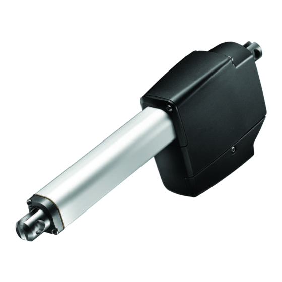
LA25 User Manual | Introduction Extremely powerful linear actuator able to create reliable movement in most environments� Comes with LINAK Integrated Controller (IC) and ideal for arduous outdoor environments� ® Tough applications require equally tough actuator solutions� The actuator LA25 is specifically developed for heavy-duty applications in environments where temperature, moist or dust are causing problems and where there is a need for high lifting capacity and holding load�... - Page 7 LA25 User Manual | During operation, please be aware of the following: • Listen for unusual sounds and watch out for uneven running� Stop the actuator immediately if anything unusual is observed� • Do not sideload the actuator� • Only use the actuator within the specified working limits� •...
-
Page 8: Features
LA25 User Manual | Features • 12 V/24 V DC permanent magnetic motor • Load from 600 N - 2�500 N in push and pull • Speed from 2�5 to 25 mm/seconds depending on load and spindle pitch (Zero Point: 100 to 600 mm) •... -
Page 9: Speed And Current Curves
LA25 User Manual | Speed and current curves The charts below display typical values made with a stable power supply and an ambient temperature of 20˚C� LA25 - 12 V Speed vs Load 20 mm 12 mm 9 mm 6 mm 3 mm 1000 1500... - Page 10 LA25 User Manual | 10 Speed and Current Curves The charts below display typical values made with a stable power supply and an ambient temperature of 20˚ C� LA25 - 24 V Speed vs Load 20 mm 12 mm 9 mm 6 mm 3 mm 1000...
-
Page 11: Current Limits
LA25 User Manual | 11 Current limits Platform Movement 12 V 24 V 48 V Temperature Outwards 13 A Above Inwards 13 A B, C, F Reference temperature 0°C Outwards 26 A 16 A Below Inwards 26 A 16 A If the actuator's current consumption rises above the set limit, the actuator regulates and tries to keep it below the set current limit by reducing the PWM and therefore also the speed accordingly�... -
Page 12: Dimensions
LA25 User Manual | 12 Dimensions Electrical installation For Standard actuators: • To ensure maximum self-locking ability, please be sure that the motor is shorted when stopped� When using soft stop on a DC-motor, a short peak of higher voltage will be sent back towards the power supply�... -
Page 13: Without Feedback
LA25 User Manual | 13 Without feedback Connection diagram Deutsch Fig� 1: 25xxxxxxxx000x0x=xxxxx00xxxxxx BROWN BLUE I/O specifications Input/Output Specification Comments Description Permanent magnetic DC motor� 12-24 V DC (+/-) To extend actuator: Brown Brown to positive 12 V ± 20% Blue to negative 24 V ±... -
Page 14: Endstop Reached
LA25 User Manual | 14 Endstop reached Connection diagram Deutsch Fig� 2: 25xxxxxxxx000x0x=xxxxx10xxxxxx BROWN BLUE Supply for feedback + RED Digital output YELLOW Digital output GREEN Supply for feedback - BLACK If you wish to use the endstop signals, you will have to keep power on the Red, Black, Brown and Blue wires, otherwise the signal will be lost�... - Page 15 LA25 User Manual | 15 Endstop reached I/O specifications Input/Output Specification Comments The actuator provides an electronic controlled signal on Description the Yellow or Green wire when the endstop is reached� 12-24 V DC (+/-) To extend actuator: Brown 12 V ± 20% Brown to positive 24 V ±...
-
Page 16: Single Hall
LA25 User Manual | 16 Single Hall Connection diagram Deutsch Fig� 3: 25xxxxxxxx0K0x0x=xxxxx00xxxxxx BROWN BLUE Supply for feedback + RED Single Hall Digital output VIOLET Supply for feedback - BLACK... - Page 17 LA25 User Manual | 17 Single Hall I/O specifications Input/Output Specification Comments Single Hall The actuator is equipped with Single Hall that provides a Description feedback signal when the actuator moves� 12-24 V DC (+/-) To extend actuator: Brown Brown to positive 12 V ±...
-
Page 18: Single Hall
LA25 User Manual | 18 Endstop reached - Single Hall Connection diagram Deutsch Fig� 4: 25xxxxxxxx0K0x0x=xxxxx10xxxxxx BROWN BLUE Supply for feedback + RED Single Hall Digital output VIOLET Digital output YELLOW Digital output GREEN Supply for feedback - BLACK If you wish to use the endstop signals, you will have to keep power on the Red, Black, Brown and Blue wires, otherwise the signal will be lost�... - Page 19 LA25 User Manual | 19 Endstop reached - Single Hall I/O specifications Input/Output Specification Comments Single Hall The actuator is equipped with Single Hall that provides a Description feedback signal when the actuator moves� To extend actuator: 12-24 V DC (+/-) Brown Brown to positive 12 V ±...
-
Page 20: Absolute Positioning - Analogue Feedback
LA25 User Manual | 20 Absolute positioning - Analogue feedback Connection diagram Deutsch Fig� 5: 25xxxxxxxx0A0x0x=xxxxx0xxxxxxx BROWN BLUE Supply for feedback + RED Analogue output VIOLET Supply for feedback - BLACK... - Page 21 LA25 User Manual | 21 Absolute positioning - Analogue feedback I/O specifications Input/Output Specification Comments The actuator is equipped with an electronic circuit that Description gives an analogue feedback signal, which indicates the position of the actuator� To extend actuator: 12-24 V DC (+/-) Brown Brown to positive...
-
Page 22: Endstop Reached And Absolute Positioning - Analogue Feedback
LA25 User Manual | 22 Endstop reached and absolute positioning - Analogue feedback Connection diagrams Deutsch Fig� 6: 25xxxxxxxx0A0x0x=xxxxx1xxxxxxx BROWN BLUE Supply for feedback + RED Analogue output VIOLET Digital output YELLOW Digital output GREEN Supply for feedback - BLACK *YELLOW/GREEN: Endstop signals out are NOT potential free If you wish to use the endstop signals, you will have to keep power on the Red, Black, Brown and Blue wires�... - Page 23 LA25 User Manual | 23 Endstop reached and absolute positioning - Analogue feedback I/O specifications Input/Output Specification Comments The actuator provides an electronically controlled feedback indicating the position and an electronically Description controlled signal on the Yellow or Green wire when endstop is reached�...
-
Page 24: Absolute Positioning - Pwm
LA25 User Manual | 24 Absolute positioning - PWM Connection diagram Fig� 7: 25xxxxxxxx0F0x0x=xxxxx0xxxxxxx Deutsch BROWN BLUE Supply for feedback + RED Digital feedback VIOLET 50% 50% Supply for feedback - BLACK... - Page 25 LA25 User Manual | 25 Absolute positioning - PWM I/O specifications Input/Output Specification Comments The actuator provides feedback which indicates the 50% 50% Description actuator position by using the Pulse Width Modulation principle� 12-24 V DC (+/-) To extend actuator: Brown Brown to positive 12 V ±...
-
Page 26: Endstop Reached And Absolute Positioning - Pwm
LA25 User Manual | 26 Endstop reached and absolute positioning - PWM Connection diagram Deutsch Fig� 8: 25xxxxxxxx0F0x0x=xxxxx1xxxxxxx BROWN BLUE Supply for feedback + RED Digital feedback VIOLET 50% 50% Digital output YELLOW Digital output GREEN Supply for feedback - BLACK If you wish to use the endstop signals, you will have to keep power on the Red, Black, Brown and Blue wires, otherwise the signal will be lost�... - Page 27 LA25 User Manual | 27 Endstop reached and absolute positioning - PWM I/O specifications Input/Output Specification Comments The actuator provides an electronically controlled feedback of the position using the Pulse Width 50% 50% Modulation principle� Description A signal is also provided when the actuator reaches its endstop position�...
-
Page 28: Ic Basic
LA25 User Manual | 28 IC Basic Connection diagram Fig� 9: 25xxxxxxxxxxxx1x=xxxxx18xxxxxx Deutsch 12/24 V DC + BROWN GND - BLUE Digital input Digital input BLACK Digital output YELLOW Digital output GREEN... - Page 29 LA25 User Manual | 29 IC Basic I/O specifications Input/Output Specification Comments Easy to use interface with integrated power electronics (H-bridge)� Description The version with “IC option” cannot be operated with PWM power supply� Connect Brown to positive 12-24 V DC + (VCC) 12 V + 20% 24 V + 10% Typical values at max�...
-
Page 30: Ic Advanced
LA25 User Manual | 30 IC Advanced Connection diagram Deutsch Fig� 10: 25xxxxxxxxxx3x1x=xxxxxAxxxxxxx 12/24 V DC + BROWN GND - BLUE Digital input Digital input BLACK Single Hall Feedback VIOLET Signal GND WHITE 50% 50% 4-20 mA Digital output YELLOW Digital output GREEN Please be aware that if the power supply is not properly connected, you might damage the actuator! - Page 31 LA25 User Manual | 31 IC Advanced I/O specifications I/O specifications Input/Output Specification Comments Easy-to-use interface with integrated power electronics (H-bridge)� The actuator is also equipped with an electronic circuit that gives an absolute or relative feedback signal� Description Actuators with “IC” cannot be operated with PWM, as this can damage the actuator�...
- Page 32 LA25 User Manual | 32 IC Advanced I/O specifications Ripple max�: 200 mV Analogue feedback range (0-10 V): Transaction delay: 20 ms Configure any min�/max� value between 0-10 V Linear feedback: max� 0�5% deviation Max� current output: 1 mA Single Hall output (PNP) Movement per Single Hall count: LA25030 Actuator = 0�125 mm per count LA25060 Actuator = 0�250 mm per count...
-
Page 33: Correct Wiring Of Power Gnd And Signal Gnd For Ic Advanced
LA25 User Manual | 33 Correct Wiring of Power GND and Signal GND for IC Advanced Power connector BROWN POWER Power supply BLUE POWER GND Control connector Hall VIOLET FEEDBACK 0-10 V Feedback input WHITE SIGNAL GND LA25 IC actuator Please note: This section only applies for 0-10 V, Hall and PWM feedback options�... -
Page 34: Ic Options Overview
LA25 User Manual | 34 IC options overview Basic Advanced Parallel LIN bus CAN bus CANopen IO-Link Control 12 V, 24 V supply √ √ √ √ √ √ √* H-bridge √ √ √ √ √ √ √ Manual drive in/out √... -
Page 35: Feedback Configurations Available For Ic Advanced And Parallel
LA25 User Manual | 35 Feedback configurations available for IC Advanced and Parallel Pre-configured Customised range Pros Cons None Suitable for long More complex distance transmission� 10 – 90% 0 – 100% processing required PWM feedback* 75 Hz 75 – 150 Hz compared to AFV and Effectual immunity to AFC�... -
Page 36: Actuator Configurations Available For Ic Advanced And Parallel
LA25 User Manual | 36 Actuator configurations available for IC Advanced and Parallel Customised range (IC Basic - Only speed, Pre-configured Description soft stop and current limits optional) 8 A with 12 V 5 A with 24 V Valid for both current limit Current limit directions�... -
Page 37: Ic Parallel
LA25 User Manual | 37 IC Parallel Connection diagram Deutsch Fig� 11: 25xxxxxxxxxx3x1x=xxxxxxZxxxxxx Actuator 8 Actuator 7 Actuator 6 Actuator 5 Actuator 4 Actuator 3 Actuator 2 Actuator 1 Positive BROWN Negative BLUE Digital input BLACK Digital input Parallel VIOLET Signal GND WHITE Digital output... - Page 38 LA25 User Manual | 38 IC Parallel I/O specifications Input/Output Specification Comments Parallel drive of up to 8 actuators� A Master actuator with an integrated H-bridge controller Description controls up to 7 Slaves� Actuators with “IC” cannot be operated with PWM power supply�...
-
Page 39: The Parallel System
LA25 User Manual | 39 The Parallel System The Parallel drive function will support a number of actuators working jointly� Power BLUE Power Power Power Supply Supply Supply Supply 12/24 V 12/24 V 12/24 V 12/24 V BROWN BLACK VIOLET Communication WHITE Signal GND... -
Page 40: Buslink Software Tool And The Parallel System
LA25 User Manual | 40 BusLink Software Tool and the Parallel System The BusLink software tool is available for Parallel and can be used for configuration, manual run and diagnostics (service counter) For more information and easy set-up of BusLink, please follow the link to view the Quick Guide for BusLink here�... -
Page 41: System Monitoring For Parallel
LA25 User Manual | 41 System Monitoring for Parallel If one of the actuators is experiencing one of the following error conditions, the actuators will immediately STOP: • H-bridge fault • Out of the temperature range (high duty cycle protection) •... -
Page 42: Parallel Manual Service Mode
LA25 User Manual | 42 Parallel Manual Service Mode With the Parallel Manual Service Mode it is possible to drive one or more Parallel actuators separately by using the Red and Black wire from each actuator� Please follow this procedure to manually extend/retract the Parallel actuator(s): Procedure Min. -
Page 43: I/O Basic
Connect the actuator to Actuator Connect via Bluetooth ® or a USB adapter cable (must be purchased separately), and request an unlock key from your local LINAK office� ® The Bluetooth word mark and logos are registered trademarks owned by Bluetooth SIG Inc�, and any use of such ®... - Page 44 Find more information about the I/O actuators in the I/O interface user manual The newest version is available online here� The Bluetooth word mark and logos are registered trademarks owned by Bluetooth SIG Inc�, and any use of such ® marks and logos by LINAK is under license� ®...
-
Page 45: I/O Customised Or Full
If 'endstop reached' is not used, a 6-pin connector can be chosen, where the alternative pins are used� The Bluetooth word mark and logos are registered trademarks owned by Bluetooth SIG Inc� and any use of such ® marks and logos by LINAK is under license� ®... - Page 46 USB adapter cable (must be purchased separately) to enable and ™ ® configure various features� The Bluetooth word mark and logos are registered trademarks owned by Bluetooth SIG Inc� and any use of such marks ® and logos by LINAK is under license� ®...
- Page 47 Antenna for Bluetooth ® connection, and has no functionality during operation� The Bluetooth word mark and logos are registered trademarks owned by Bluetooth SIG Inc� and any use of such marks ® and logos by LINAK is under license� ®...
-
Page 48: Can Bus J1939
HW Addressing pin 3 The BusLink software tool is available for CAN bus actuators and can be used for diagnostics, manual arun and configuration The newest version is available online at LINAK�COM/TECHLINE Please note: The BusLink configuration cable must be purchased separately... - Page 49 LA25 User Manual | 49 CAN bus J1939 I/O specifications Input/Output Specification Comments Compatible with the SAE J1939 standard� Uses CAN messages to command movement, setting parameters and to deliver feedback from the Description actuator� Actuator identification is provided using standard J1939 address claim or fixed addresses�...
-
Page 50: Can Bus J1939 Zero Point
CAN bus Zero Point actuators and can be used for: ® Diagnostics, manual run and configuration The newest version is available online at LINAK�COM/TECHLINE Connect the actuator to Actuator Connect via Bluetooth or a USB adapter cable (must be purchased ®... - Page 51 The standard/default cables delivered with CAN actuators do not comply with this� BusLink cables must be purchased separately from the actuator! Find more information about the CAN bus actuators in the CAN bus user manual The newest version is available online at LINAK�COM/TECHLINE...
-
Page 52: Canopen
Please be aware that if the power supply is not properly connected, you might damage the actuator! The BusLink software tool is available for CAN bus actuators and can be used for diagnostics, manual run and configuration The newest version is available online at LINAK.COM/TECHLINE Please note: The BusLink configuration cable must be purchased separately... - Page 53 LA25 User Manual | 53 CANopen I/O specifications Input/Output Specification Comments Compatible with the CiA 301 standard� Us CANopen messages to command movement, setting parameters and to deliver feedback from Description the actuator� Actuator identification is provided using standard CiA 301 address claim or fixed addresses Connect Brown to positive 12-24 V DC + (VCC) Vsup...
- Page 54 LA25 User Manual | 54 CANopen I/O specifications CANopen assumes a physical layer according to ISO 11898-2� Yellow CAN_H Speed: Autobaud up to 250 kbps (Prototypes: 125 kbps) Max� bus length at 125 kbps: 500 m Max� bus length at 250 kbps: 250 m Max�...
-
Page 55: Lin Bus
LA25 User Manual | 55 LIN bus Connection diagram Fig� 17: 25 Fig� 17: 25 6x1x= 6x1x= Deutsch xxxxxxxxxx xxxxxxxxxx xxxxxxxxxxxxx xxxxxxxxxxxxx 24 V DC + BROWN GND - BLUE Digital input Digital input BLACK Communication VIOLET Communication WHITE... - Page 56 LIN bus I/O specifications Input/Output Specification Comments Each LINAK actuator with LIN bus interface has the ® ability to act as LIN bus slave node in the LIN bus cluster� The LIN bus is able to provide feedback information about piston position, including if endstop is reached,...
-
Page 57: Io-Link
The LA25 with IO-Link and M12 connector is a plug-and-play solution� If flying leads is 2M GND - BLUE the preferred option, please be aware that the LINAK cable colours differ from the ® IO-Link standard� The cable colours from the actuator and the M12 port numbers are specified in the table below�... - Page 58 LA25 User Manual | 58 IO-Link I/O specifications Input/Output Specification Comments IO-Link is standardised IO technology (IEC 61131-9) for the communication with actuators� The point-to- point communication is based on the long established Description actuator connection without additional requirements regarding the cable material� IO-Link is no fieldbus but the furorther development of the existing, tried-and- tested connection technology for actuators�...
-
Page 59: Test Of Conducted And Radiated Emission (Emc)
The actuator has been tested when operating with constant 80%-PWM� • Radiated emission requirements are met • Conducted emission requirements are met 2) For systems with LINAK PWM regulation (among other things Parallel operation and speed regulation) ® the following is valid: •... -
Page 60: Iecex/Atex Certified (Optional)
LA25 User Manual | 60 IECEx/ATEX certified (optional) LA25 can be ordered as an Ex certified version designed for installation in dust-filled atmospheres such as grain handling facilities, cement plants, saw mills or other dusty surroundings� Please note: This approval is only valid for dusty environments, NOT for gas� The IECEx/ATEX versions are suitable for applications in Group IIIC, Category 2D�... -
Page 61: Label For La25 Iece/Atex Special Item
LA25 User Manual | 61 Label for LA25 IECE/ATEX special item LA25 can be ordered as an Ex certified version designed for installation in dust-filled atmospheres such as grain handling facilities, cement plants, saw mills or other dusty surroundings, but in lower ambient temperatures as with the standard Ex approval�... -
Page 62: Iecex/Atex Certified (Optional)
• No changes are to be made to the actuator after delivery� This manual is part of the equipment� LINAK A/S keeps the right to modify specifications without advanced notice� Spare this manual for later use... -
Page 63: Mounting And Replacement Of Atex Cables
4� Safety and operation instructions are accessible and followed 5� The production of IECEx/ATEX actuators require quality management systems and auditing� Therefore, only LINAK A/S is allowed to produce, modify or repair actuators in order to sustain the certification� IECEx/ATEX... -
Page 64: Replacing An Atex Cable
LA25 User Manual | 64 Replacing an ATEX cable Loosen the screw to disassemble the cable relief� Remove the cable relief by pulling it in the same direction as the screw� Remove the plugged cable� Insert the cable (0147006-xxxx) with an ATEX-approved O-ring�... - Page 65 LA25 User Manual | 65 Correct mounting of cable The brown O-ring is not visible� Incorrect mounting of cable The brown O-ring is visible and the application is NOT tight� Place the cable relief on the actuator housing, then place and tighten the screw� Fasten it to 3 Nm ±...
-
Page 66: Eu-Type Examination Certificate
Directive 2014/34/EU Certificate Number TÜV 15 ATEX 143744 X Issue: Linear Actuator, Model: LA25 series for the product: of the manufacturer: LINAK A/S Address: Smedevænget 8, Guderup 6430 Nordborg Denmark Order number: 8003051498 Date of issue:... - Page 67 LA25 User Manual | 67 S C H E D U L E (13) (14) EU-Type Examination Certificate TÜV 15 ATEX 143744 X Issue 01 (15) Description of product The LA25 series of linear actuators creates motion in a straight line, as contrasted with circular motion of a conventional electric motor.
- Page 68 3. The power supply cable is of special design fulfilling IP 6X ingress protection. The cable can be delivered in different lengths. Only cables delivered by LINAK A/S shall be mounted. 4. The connection between the actuator and the rest of the machine/device shall be conductive, and furthermore the application shall be grounded in order to remove any Electro Static Discharge.
-
Page 69: Declaration Of Conformity
LA25 User Manual | 69 DECLARATION OF CONFORMITY LINAK A/S Smedevænget 8 DK - 6430 Nordborg Hereby declares that Actuator 25**********0***************** 25**********3***************** 25*****CD****** (The ‘*’s in the product description can either be a character or a number, thereby defining the variation of the product) - Page 70 LA25 User Manual | 70 DECLARATION OF CONFORMITY LINAK A/S Smedevænget 8 DK - 6430 Nordborg Hereby declares that Actuator (LA25IO) 25**********B***=*************, 25**********C***=*************, 25**********F***=************* (The ‘*’ in the product description can either be a character or a number, thereby defining the variation of...
- Page 71 LA25 User Manual | 71 DECLARATION OF CONFORMITY LINAK A/S Smedevænget 8 DK - 6430 Nordborg Hereby declares that Actuator (LA25 CAN) 25**********6A****************, 25**********6B**************** 25**********7A****************, 25**********7B**************** 25**********9A****************, 25**********9B**************** (The ‘*’ in the product description can either be a character or a number, thereby defining the variation of the product)
- Page 72 LA25 User Manual | 72 DECLARATION OF CONFORMITY LINAK A/S Smedevænget 8 DK - 6430 Nordborg Hereby declares that Actuator (LA25IO-Link) 25********00AB**=******0*00*** (The ‘*’ in the product description can either be a character or a number, thereby defining the variation of...
-
Page 73: Contacts
LINAK, LINAK subsidiaries, or LINAK affiliates. the same reason, LINAK cannot guarantee the correctness and actual status of imprinted information on All sales are subject to the ‘Standard Terms of Sale and Delivery for LINAK A/S’ available on LINAK websites. its products.
Need help?
Do you have a question about the TechLine LA25 and is the answer not in the manual?
Questions and answers