
Related Manuals for Mitsubishi Electric Mr.SLIM PEY Series


Summary of Contents for Mitsubishi Electric Mr.SLIM PEY Series
- Page 1 2018 SPLIT-TYPE AIR CONDITIONERS SERVICE MANUAL Series PEY Model name Model name <Indoor unit> <Indoor unit> PEY-P18JAG PEY-P24JAG PEY-P30JAG PEY-P36JAG PEY-P45JAG INDOOR UNIT...
-
Page 2: Table Of Contents
CONTENTS 1. SAFETY PRECAUTIONS ········································································· 3 1-1. Always observe for safety ...................... 3 1-2. Cautions related to new refrigerant ..................3 2. PART NAMES AND FUNCTIONS ······························································ 5 2-1. Indoor unit ..........................5 2-2. Wireless remote controller ..................... 6 2-3. Wired remote controller <PAR-31MAA> ................7 2-4. -
Page 3: Safety Precautions
SAFETY PRECAUTIONS 1. SAFETY PRECAUTIONS 1-1. Always observe for safety Before obtaining access to terminal, all supply circuits must be disconnected. 1-2. Cautions related to new refrigerant Cautions for units utilising refrigerant R410A Use new refrigerant pipes. Use a vacuum pump with a reverse flow check valve. - Page 4 SAFETY PRECAUTIONS <2> Additional refrigerant charge When charging directly from cylinder • Check that cylinder for R410A on the market is syphon type. • Charging should be performed with the cylinder of syphon stood vertically. (Refrigerant is charged from liquid phase.) Unit Gravimeter <3>...
-
Page 5: Part Names And Functions
PART NAMES AND FUNCTIONS 2. PART NAMES AND FUNCTIONS 2-1. Indoor unit Air intake (sucks the air inside the room into the unit) Air outlet In case of rear inlet In case of bottom inlet HWE18090... -
Page 6: Wireless Remote Controller
PART NAMES AND FUNCTIONS 2-2. Wireless remote controller CHECK TEST RUN display CHECK and TEST RUN display indicate that the unit is being checked or test-run. MODEL SELECT display Blinks when model is selected. display Lights up while the signal is transmitted to the indoor unit when the button is pressed. -
Page 7: Wired Remote Controller
PART NAMES AND FUNCTIONS 2-3. Wired remote controller <PAR-31MAA> 2-3-1. Wired remote controller function * The functions which can be used are restricted according to the model. : Supported : Unsupported PAR-31MAA Function PAR-21MAA Slim City multi Product size H × W × D (mm) 120 ×... - Page 8 PART NAMES AND FUNCTIONS The main display can be displayed in two different modes: "Full" and "Basic". The factory setting is "Full". To switch to the "Basic" mode, change the setting on the Main display setting. <Full mode> <Basic mode> * All icons are displayed for explanation.
-
Page 9: Menu Structure
PART NAMES AND FUNCTIONS 2-3-2. Menu structure Press the [MENU] button. Move the cursor to the desired item with the [F1] and [F2] buttons, and press the [SELECT] button. Main menu Vane · Louver · Vent. (Lossnay) High power Timer On / Off timer Auto-Off timer Filter information... - Page 10 PART NAMES AND FUNCTIONS 2-3-3. Main menu list Setting and display items Setting details Use to set the vane angle. • Select a desired vane setting from five different settings. Vane · Louver · Vent. Use to turn ON / OFF the louver. • Select a desired setting from "ON"...
- Page 11 PART NAMES AND FUNCTIONS Setting and display items Setting details Make the settings for the remote controller related items as necessary. Clock: The factory settings are "Yes" and "24h" format. Display details Temperature: Set either Celsius (°C) or Fahrenheit (°F). Room temp.
-
Page 12: Wired Remote Controller
PART NAMES AND FUNCTIONS 2-4. Wired remote controller <PAR-21MAA> “Sensor” indication Display Section Displays when the remote controller sensor is used. Day-of-Week For purposes of this explanation, Shows the current day of the week. all parts of the display are shown. During actual operation, only Time/Timer Display the relevant items will be lit. -
Page 13: Specification
SPECIFICATION 3. SPECIFICATION Model name PEY-P18JAG PEY-P24JAG Mode Cooling Cooling Single phase, Single phase, Power supply 50Hz 220-240V, 60Hz 220V 50Hz 220-240V, 60Hz 220V Input 0.09 0.15 Running Current 0.79 1.17 External finish Galvanized sheets Galvanized sheets Heat exchanger Plate fin coil Plate fin coil Fan (drive) ×... -
Page 14: Fan Performance And Corrected Air Flow
FAN PERFORMANCE AND CORRECTED AIR FLOW 4. FAN PERFORMANCE AND CORRECTED AIR FLOW PEY-P18JAG PEY-P18JAG (External static pressure 35Pa) 220-240V 50Hz / 220V 60Hz (External static pressure 100Pa) 220-240V 50Hz / 220V 60Hz High Limit Limit Middle High Middle Airflow rate(m /min) Airflow rate(m /min) - Page 15 FAN PERFORMANCE AND CORRECTED AIR FLOW PEY-P24JAG PEY-P24JAG (External static pressure 35Pa) 220-240V 50Hz / 220V 60Hz (External static pressure 100Pa) 220-240V 50Hz / 220V 60Hz High Limit Limit High Middle Middle Airflow rate(m /min) Airflow rate(m /min) PEY-P24JAG PEY-P24JAG (External static pressure 50Pa) 220-240V 50Hz / 220V 60Hz (External static pressure 125Pa) 220-240V 50Hz / 220V 60Hz High...
- Page 16 FAN PERFORMANCE AND CORRECTED AIR FLOW PEY-P30JAG PEY-P30JAG (External static pressure 35Pa) 220-240V 50Hz / 220V 60Hz (External static pressure 100Pa) 220-240V 50Hz / 220V 60Hz Limit High Limit Middle High Middle Airflow rate(m /min) Airflow rate(m /min) PEY-P30JAG PEY-P30JAG (External static pressure 50Pa) 220-240V 50Hz / 220V 60Hz (External static pressure 125Pa) 220-240V 50Hz / 220V 60Hz Limit...
- Page 17 FAN PERFORMANCE AND CORRECTED AIR FLOW PEY-P36, 45JAG PEY-P36, 45JAG (External static pressure 35Pa) 220-240V 50Hz / 220V 60Hz (External static pressure 100Pa) 220-240V 50Hz / 220V 60Hz Limit High Limit High Middle Middle Airflow rate(m /min) Airflow rate(m /min) PEY-P36, 45JAG PEY-P36, 45JAG (External static pressure 50Pa) 220-240V 50Hz / 220V 60Hz...
-
Page 18: Sound Pressure Levels
SOUND PRESSURE LEVELS 5. SOUND PRESSURE LEVELS 5-1. Sound pressure level <1> Ceiling concealed Aux. duct test unit Measurement location HWE18090... -
Page 19: Nc Curves
SOUND PRESSURE LEVELS 5-2. NC curves PEY-P18JAG PEY-P18JAG (External static pressure 35Pa) (External static pressure 100Pa) 70.0 70.0 High High Middle Middle 65.0 65.0 60.0 60.0 NC-60 NC-60 55.0 55.0 50.0 50.0 NC-50 NC-50 45.0 45.0 40.0 40.0 NC-40 NC-40 35.0 35.0 30.0... - Page 20 SOUND PRESSURE LEVELS PEY-P24JAG PEY-P24JAG (External static pressure 35Pa) (External static pressure 100Pa) 70.0 70.0 High High Middle Middle 65.0 65.0 60.0 60.0 NC-60 NC-60 55.0 55.0 50.0 50.0 NC-50 NC-50 45.0 45.0 40.0 40.0 NC-40 NC-40 35.0 35.0 30.0 30.0 NC-30 NC-30...
- Page 21 SOUND PRESSURE LEVELS PEY-P30JAG PEY-P30JAG (External static pressure 35Pa) (External static pressure 100Pa) 70.0 70.0 High High Middle Middle 65.0 65.0 60.0 60.0 NC-60 NC-60 55.0 55.0 50.0 50.0 NC-50 NC-50 45.0 45.0 40.0 40.0 NC-40 NC-40 35.0 35.0 30.0 30.0 NC-30 NC-30...
- Page 22 SOUND PRESSURE LEVELS PEY-P36, 45JAG PEY-P36, 45JAG (External static pressure 35Pa) (External static pressure 100Pa) 70.0 70.0 High High Middle Middle 65.0 65.0 60.0 60.0 NC-60 NC-60 55.0 55.0 50.0 50.0 NC-50 NC-50 45.0 45.0 40.0 40.0 NC-40 NC-40 35.0 35.0 30.0 30.0...
-
Page 23: Outlines & Dimensions
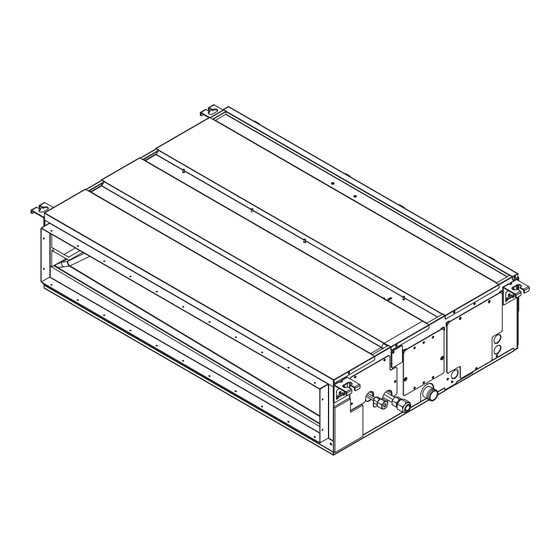
OUTLINES & DIMENSIONS 6. OUTLINES & DIMENSIONS 6-1. Indoor unit ■ PEY-P18, 24, 30, 36, 45JAG HWE18090... - Page 24 OUTLINES & DIMENSIONS HWE18090...
-
Page 25: Wiring Diagram
WIRING DIAGRAM 7. WIRING DIAGRAM ■ PEY-P18, 24, 30, 36, 45JAG HWE18090... -
Page 26: Refrigerant System Diagram
REFRIGERANT SYSTEM DIAGRAM 8. REFRIGERANT SYSTEM DIAGRAM ■ PEY-P18, 24, 30, 36, 45JAG Strainer (#50) Heat exchanger Refrigerant GAS pipe connection (Flare) Thermistor TH5 (Cond./ Eva.temperature) Refrigerant flow in cooling Refrigerant LIQUID pipe connection (Flare) Thermistor TH2 Pipe temperature(Liquid) Thermistor TH1 (Room temperature) Strainer (#50) Distributor... -
Page 27: Troubleshooting
TROUBLESHOOTING 9. TROUBLESHOOTING 9-1. Troubleshooting <1> Error code display by self-diagnosis and actions to be taken for service (summary) Present and past error codes are logged and displayed on the wired remote controller or controller board of outdoor unit. Actions to be taken for service and the trouble reoccurrence at field are summarized in the table below. Check the contents below before investigating details. -
Page 28: Malfunction-Diagnosis Method By Remote Controller
TROUBLESHOOTING 9-2. Malfunction-diagnosis method by remote controller <1> In case of trouble during operation When a malfunction occurs to air conditioner, both indoor unit and outdoor unit will stop and operation lamp blinks to inform unusual stop. <2> Malfunction-diagnosis method at maintenance service [Procedure] (1) Press the CHECK button twice. - Page 29 TROUBLESHOOTING • Refer to the following tables for details on the check codes. [Output pattern A] Beeper sounds Beep Beep Beep Beep Beep Beep Beep OPERATION · · · Repeated INDICATOR lamp flash pattern Approx. 2.5 sec. 0.5 sec. 0.5 sec. 0.5 sec.
- Page 30 TROUBLESHOOTING • On wireless remote controller The continuous buzzer sounds from receiving section of indoor unit. Blink of operation lamp • On wired remote controller 1 Check code displayed in the LCD. • If the unit cannot be operated properly after the test run, refer to the following table to find out the cause. Symptom Cause Wired remote controller...
-
Page 31: Self-Diagnosis Action Table
TROUBLESHOOTING 9-3. Self-diagnosis action table Note: Refer to the manual of outdoor unit for the details of display such as F, U, and other E. Error Code Abnormal point and detection method Cause Countermeasure Room temperature thermistor (TH1) 1 Defective thermistor 1–... - Page 32 TROUBLESHOOTING Error Code Abnormal point and detection method Cause Countermeasure Freezing/overheating protection is (Cooling or drying mode) (Cooling or drying mode) operating 1 Clogged filter (reduced airflow) 1 Check clogs of the filter. 1 Freezing protection (Cooling mode) 2 Short cycle of air path 2 Remove blockage.
- Page 33 TROUBLESHOOTING Error Code Abnormal point and detection method Cause Countermeasure Remote controller transmission error(E0)/ 1 Contact failure at transmission 1 Check disconnection or looseness of indoor signal receiving error(E4) wire of remote controller unit or transmission wire of remote controller. 1 Abnormal if main or sub remote controller 2 All remote controllers are set 2 Set one of the remote controllers “main”...
- Page 34 TROUBLESHOOTING Error Code Abnormal point and detection method Cause Countermeasure Indoor controller board 1 Defective indoor controller 1 Replace indoor controller board. Abnormal if data cannot be read normally from board (FB)* the nonvolatile memory of the indoor controller * The check code in the parenthesis indicates board.
-
Page 35: Troubleshooting Of Problems
TROUBLESHOOTING 9-4. Troubleshooting of problems Note: Refer to the manual of outdoor unit for the detail of remote controller. Phenomena Cause Countermeasure (1) LED2 on indoor controller board is • When LED1 on indoor controller board is also off. off. 1 Power supply of rated voltage is not 1 Check the voltage of outdoor power supply supplied to outdoor unit. - Page 36 TROUBLESHOOTING Note: Refer to the manual of outdoor unit for the detail of remote controller. Phenomena Cause Countermeasure (2) LED2 on indoor controller board is • When LED1 on indoor controller board is Check indoor/outdoor unit connecting wire for also blinking. connection failure.
-
Page 37: Emergency Operation
TROUBLESHOOTING 9-5. Emergency operation 9-5-1. When wireless remote controller fails or its battery is exhausted 1 ON/OFF lamp (lit when unit is operating; unlit when unit is not operating) 2 Emergency operation In cases where the remote control unit does not operate properly, use the ON/OFF COOL button on the wireless remote control signal receiver to toggle the unit on or off. -
Page 38: How To Check The Parts
TROUBLESHOOTING 9-6. How to check the parts Part name Check method and criterion Measure the resistance with a tester. Room temperature thermistor (Part temperature 10°C ~ 30°C) (TH1) Normal Abnormal Pipe temperature 4.3kΩ~9.6kΩ Opened or short-circuited thermistor/liquid (TH2) Condenser/evaporator temperature thermistor (TH5) Motor Motor winding... - Page 39 TROUBLESHOOTING 9-6-2. DC Fan motor (Fan motor/indoor controller board) <1> Check method of DC fan motor (fan motor/indoor controller circuit board) (1) Notes • High voltage is applied to the connecter (CNMF) for the fan motor. Give attention to the service. • Do not pull out the connector (CNMF) for the motor with the power supply on.
-
Page 40: Test Point Diagram
TROUBLESHOOTING 9-7. Test point diagram 9-7-1. Power supply board Power supply voltage (220 - 240VAC) CNMF Fan motor output 1 - 4: 310 - 340 VDC 5 - 4: 15 VDC 6 - 4: 0 - 6.5 VDC 7 - 4: Stop 0 or 15 VDC Run 7.5 VDC (0 - 15 pulse) Drain-up mechanism output (200VAC) - Page 41 TROUBLESHOOTING 9-7-2. Indoor controller board CN22 Emergency operation Model selection Capacity setting CN32 Remote start/stop adapter CN22 For MA remote controller cable con- nection (10 - 13 VDC (Between 1 and 3.)) CN51 Centralized control CN41 JAMA standard HA terminal A CN32 CN44 Thermistor (liquid/condenser/evaporator...
-
Page 42: Functions Of Dip Switch And Jumper Wire
TROUBLESHOOTING 9-8. Functions of dip switch and jumper wire Each function is controlled by the dip switch and the jumper wire on control p.c. board. SW1 and SW2 are equipped only for service parts. Model setting and capacity setting are memorized in the nonvolatile memory of the control p.c. board of the unit. (Marks in the table below) Jumper wire ( ○: Short ×: Open) Jumper wire Functions... -
Page 43: Disassembly Procedure
DISASSEMBLY PROCEDURE 10. DISASSEMBLY PROCEDURE Exercise caution when removing heavy parts. 10-1. Control box 1. Removing the control box cover (1) Remove the two fixing screws on the cover (A) to remove it. Fig. 1 Fig. 2 10-2. Thermistor (Intake air) 1. -
Page 44: Drainpan
DISASSEMBLY PROCEDURE Exercise caution when removing heavy parts. 10-3. Drainpan 1. Removing the filter and the bottom plate (1) Push up the tab on the filter, and pull out the filter in the direction of the arrow 1. (2) Remove the fixing screws on the bottom plate (D), (E) to remove it. -
Page 45: Thermistor (Condenser/Evaporator) (Liquid Pipe)
DISASSEMBLY PROCEDURE Exercise caution when removing heavy parts. 10-4. Thermistor (Condenser/evaporator) (Liquid pipe) 1. Remove the drain pan according to the procedure in section 10-3. Drainpan (page44). 2. Removing the Heat exchanger cover (1) Remove the four fixing screws on the heat exchanger cover (F) to remove it. -
Page 46: Fan And Fan Motor
DISASSEMBLY PROCEDURE Exercise caution when removing heavy parts. 10-5. Fan and fan motor 1. Removing the filter and the bottom plate (1) Push down the tab on the filter, and pull out the filter in the direction of the arrow 1. (2) Remove the fixing screws on the bottom plate (J) to remove it. -
Page 47: Heat Exchanger
DISASSEMBLY PROCEDURE Exercise caution when removing heavy parts. 10-6. Heat exchanger 1. Remove the drain pan according to the procedure in section 10-3. Drainpan (page44). 2. Remove the heat exchanger cover according to the procedure in section 10-4. 2. Removing the Heat exchanger cover (page45). - Page 48 www.MitsubishiElectric.com New publication effective Aug. 2018 Specifications subject to change without notice HWE18090...
Need help?
Do you have a question about the Mr.SLIM PEY Series and is the answer not in the manual?
Questions and answers