
Related Manuals for ASROCK Rack SP2C741D16X-2T


Summary of Contents for ASROCK Rack SP2C741D16X-2T
- Page 1 SP2C741D16X-2T User Manual Version 1.0 Published April 2023 Copyright©2023 ASRock Rack INC. All rights reserved.
-
Page 2: Copyright Notice
In no event shall ASRock Rack, its directors, officers, employees, or agents be liable for any indirect, special, incidental, or consequential damages (including damages for loss of... - Page 3 INTEL END USER SOFTWARE LICENSE AGREEMENT IMPORTANT - READ BEFORE COPYING, INSTALLING OR USING. LICENSE. Licensee has a license under Intel’s copyrights to reproduce Intel’s Software only in its unmodified and binary form, (with the accompanying documentation, the “Software”) for Licensee’s personal use only, and not commercial use, in connection with Intel-based products for which the Software has been provided, subject to the following conditions: (a) Licensee may not disclose, distribute or transfer any part of the Software, and You agree...
- Page 4 U.S. GOVERNMENT RESTRICTED RIGHTS. The Software is a commercial item (as defined in 48 C.F.R. 2.101) consisting of commercial computer software and commercial computer software documentation (as those terms are used in 48 C.F.R. 12.212), consistent with 48 C.F.R. 12.212 and 48 C.F.R 227.7202-1 through 227.7202-4. You will not provide the Software to the U.S.
- Page 5 ASRock Rack follows the green design concept to design and manufacture our products, and makes sure that each stage of the product life cycle of ASRock Rack product is in line with global environmental regulations. In addition, ASRock Rack disclose the relevant in- formation based on regulation requirements.
-
Page 6: Table Of Contents
Contents Chapter 1 Introduction Package Contents Specifications Unique Features Motherboard Layout Onboard LED Indicators I/O Panel Block Diagram Chapter 2 Installation Screw Holes Pre-installation Precautions Installing the CPU and Heatsink Installing Memory Modules (DIMM) 2.4.1 Memory Support 2.4.2 Memory Configurations Expansion Slots (PCI Express Slots) Jumper Setup Onboard Headers and Connectors... - Page 7 Chapter 3 UEFI Setup Utility Introduction 3.1.1 UEFI Menu Bar 3.1.2 Navigation Keys Main Screen 3.2.1 Motherboard Information 3.2.2 Processor Information 3.2.3 Memory Information Advanced Screen 3.3.1 CPU Configuration 3.3.2 Platform Power Configuration 3.3.3 DRAM Configuration 3.3.4 Chipset Configuration 3.3.5 Storage Configuration 3.3.6 NVMe Configuration 3.3.7 ACPI Configuration 3.3.8 USB Configuration...
- Page 8 3.3.16 Driver Health 3.3.17 Tls Auth Configuration 3.3.18 Instant Flash Server Mgmt 3.4.1 BMC Network Configuration 3.4.2 System Event Log 3.4.3 BMC Tools Security 3.5.1 Key Management Event Logs Boot Screen Exit Screen Chapter 4 Software Support Download and Install Operating System Download and Install Software Drivers Contact Information Chapter 5 Troubleshooting...
-
Page 9: Chapter 1 Introduction
In case any modifications of this manual occur, the updated version will be available on ASRock Rack website without further notice. Find the latest memory and CPU support lists on ASRock Rack website as well. ASRock Rack’s Website: www.ASRockRack.com About this motherboard technical support, please visit the website for specific information http://www.asrockrack.com/support/... -
Page 10: Specifications
1.2 Specifications SP2C741D16X-2T Physical Status Form Factor EEB like Dimension 12.4" x 14" (314.96 x 355.6mm) Processor System Supports 4 and 5 Gen Intel® Xeon® Scalable Processors Socket 1+1 Socket E (LGA 4677) Thermal Design 350W Power (TDP) Chipset Intel® C741... - Page 11 AMI UEFI BIOS; 512Mb SPI Flash ROM Features Plug and Play (PnP), ACPI 4.0 and above compliance wake up events, SMBIOS 3.4 and above , ASRock Rack Instant Flash Internal Connectors/Headers PSU Connectors 1 (24-pin, ATX main power), 2 (8-pin, ATX 12V) 2 (8-pin, add-on card power &...
- Page 12 80 Debug Port LED 1 Fan Fail LED BMC Heartbeat Supported OS Microsoft® Windows® - Server 2022 (64bit) Linux® - Red Hat Enterprise Linux Server 8.4 (64bit) / 8.5 (64bit) / 9.2 (64 bit) - SUSE Enterprise Linux Server 15 SP3 ( 64bit) - Ubuntu 21.10 (64bit) / 22.04 ( 64bit) Hypervisor - VMWare®...
-
Page 13: Unique Features
. With this utility, press the <F6> key during the POST or the <F2> key to enter into the BIOS setup menu to access ASRock Rack Instant Flash. Just launch this tool and save the new BIOS file to the USB flash drive, floppy disk or hard drive, then update the BIOS only in a few clicks without preparing an additional floppy diskette or other complicated flash utility. -
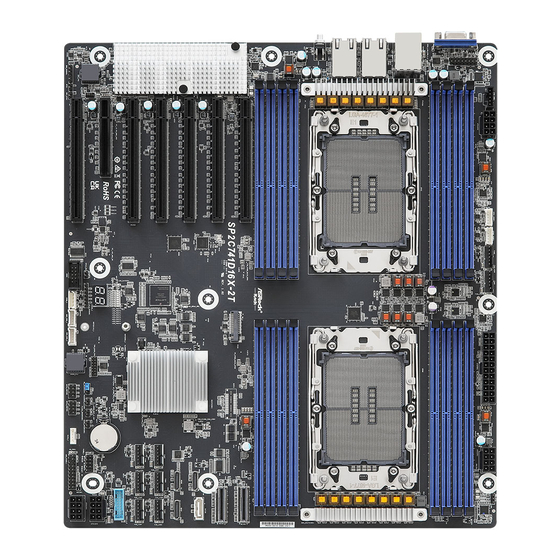
Page 14: Motherboard Layout
DDR5_B1 DDR5_M1 DDR5_A1 LAN1 CPU1 CPU0 LAN2 UID1 DDR5_I1 DDR5_E1 DDR5_J1 DDR5_F1 DDR5_K1 DDR5_G1 DDR5_L1 DDR5_H1 PCIE6 MCIO2 M2_1 SP2C741D16X-2T MCIO1 PCIE5 SATA0 X710-AT2 OCU3 PCIE4 OCU2 OCU1 PCIE3 Intel C741 FAN7 FAN5 FAN3 FAN8 FAN6 FAN4 ASPEED PCIE2 AST2600... - Page 15 SP2C741D16X-2T Description Front VGA Header (FRNT_VGA1) PSU SMBus Header (PSU_SMB1) ATX 12V Power Connector (ATX12V2) Backplane PCI Express Hot-Plug Connector (CPU1_HSBP1) Backplane PCI Express Hot-Plug Connector (CPU0_HSBP1) System Fan Connector (FAN2) System Fan Connector (FAN1) 2 x 288-pin DDR5 DIMM Slots (DDR5_N1, DDR5_P1)*...
- Page 16 Description System Panel Header (PANEL1) Virtual RAID On CPU Header (RAID_1) BIOS Swap Override Jumper (BIOS_OVERRIDE1) Flash Override Jumper (FLASH_OVERRIDE1) SATA SGPIO Connector (SATA_SGPIO1) Password Reset Jumper (PASSWORD_CLEAR1) SATA SGPIO Connector (SATA_SGPIO2) ME Recovery Jumper (ME_RECOVERY1) TPM-SPI Header (TPM_BIOS_PH1) BMC SMBus Header (BMC_SMB_2) BMC SMBus Header (BMC_SMB_1) Intelligent Platform Management Bus Header (IPMB_1) COM Header (COM1)
-
Page 17: Onboard Led Indicators
SP2C741D16X-2T 1.5 Onboard LED Indicators Item Status Description FAN_LED2 FAN2 failed FAN_LED1 FAN1 failed FAN_LED7 FAN7 failed FAN_LED5 FAN5 failed FAN_LED3 FAN3 failed FAN_LED8 FAN8 failed FAN_LED4 FAN4 failed FAN_LED6 FAN6 failed SB_PWR1 Green STB PWR ready BMC_LED1 Green BMC heartbeat LED... -
Page 18: I/O Panel
1.6 I/O Panel No. Description No. Description 10G LAN RJ-45 Port VGA Port (VGA1) (LAN1, shared NIC)** USB 2.0 Ports (USB_1_2) 10G LAN RJ-45 Port (LAN2)** LAN RJ-45 Port (IPMI_LAN)* UID Switch (UID1) IPMI LAN Port LED Indications *There is an LED on each side of IPMI LAN port. Please refer to the table below for the LAN port LED indications. - Page 19 SP2C741D16X-2T **There is an LED on each side of 10G LAN port. Please refer to the table below for the LAN port LED indications. ACT/LINK LED SPEED LED LAN Port 10G LAN Port LED Indications Activity / Link LED Speed LED...
-
Page 20: Block Diagram
1.7 Block Diagram... -
Page 21: Chapter 2 Installation
SP2C741D16X-2T Chapter 2 Installation This is a n EEB-li ke form factor (12.4" x 14") mot herboard. Before insta l ling t he motherboard, study the configuration of the chassis to ensure that the motherboard fits into it. Make sure to unplug the power cord before installing or removing the motherboard. Failure to do so may cause physical injuries and damages to motherboard components. -
Page 22: Installing The Cpu And Heatsink
2.3 Installing the CPU and Heatsink 1. Unplug all power cables before installing the CPU. 2. Illustration in this documentation are examples only. Carrier Used Carrier Type Xeon® SP XCC Xeon® SP MCC/LCC Carrier Code Shim 16.70mm 17.55mm Carrier Height XCC Carrier No Shim MCC Carrier... - Page 23 SP2C741D16X-2T Follow the steps below to finish the CPU installation and please save the Socket Dust Cover when returning for service. Socket Dust Cover CPU Carrier...
- Page 25 SP2C741D16X-2T...
- Page 26 CPU Carrier...
- Page 27 SP2C741D16X-2T Heatsink CPU Carrier Socket...
-
Page 29: Installing Memory Modules (Dimm)
SP2C741D16X-2T 2.4 Installing Memory Modules (DIMM) This motherboard provides sixteen 288-pin DDR5 (Double Data Rate 5) DIMM slots in two groups, and supports Single Channel Memory Technology. CPU0 CPU1 DDR5_A1, B1, C1, D1, E1, F1, G1 H1 DDR5_I1, J1, K1, L1, M1, N1, O1, P1 1. - Page 30 Gen Intel® Xeon® Scalable Processors - SP Speed (MT/s); Voltage (V); DRAM Density & DIMM Per Channel (DPC) Ranks Per DIMM DIMM Capacity Type and Data Width 1DPC 2DPC 16GB 24GB 32GB 1.1V SRx8 (RC D) 16GB 24GB SRx4 (RC C) 32GB 48GB SRx4 (RC F) 9x4...
-
Page 31: Memory Configurations
SP2C741D16X-2T 2.4.2 Memory Configurations 1 CPU Configurations (Single P) DIMM Number DIMM Slot CPU0 The symbol V indicates the slot is populated. - Page 32 2 CPU Configurations (Dual P) DIMM Number DIMM Slot CPU0 DIMM Number DIMM Slot CPU1 The symbol V indicates the slot is populated.
- Page 33 SP2C741D16X-2T...
-
Page 34: Expansion Slots (Pci Express Slots)
2.5 Expansion Slots (PCI Express Slots) There are 7 PCI Express slots on this motherboard. PCIE slots: PCIE0 (PCIE 5.0 x16 slot, from CPU1) is used for PCI Express x16 lane width cards. PCIE1 (PCIE 5.0 x8 slot, from CPU0) is used for PCI Express x8 lane width cards. PCIE2 (PCIE 5.0 x16 slot, from CPU1) is used for PCI Express x16 lane width cards. -
Page 35: Jumper Setup
SP2C741D16X-2T 2.6 Jumper Setup The illustration shows how jumpers are setup. When the jumper cap is placed on the pins, the jumper is “Short”. If no jumper cap is placed on the pins, the jumper is “Open”. The illustration shows a 3-pin jumper whose pin1 and pin2 are “Short” when a jumper cap is placed on these 2 pins. -
Page 36: Onboard Headers And Connectors
2.7 Onboard Headers and Connectors Onboard headers and connectors are NOT jumpers. Do NOT place jumper caps over these headers and connectors. Placing jumper caps over the headers and connectors will cause permanent damage to the motherboard. System Panel Header Connect the power switch, PLED+ PLED-... - Page 37 SP2C741D16X-2T Auxiliary Panel Header This header supports multiple (18-pin AUX PANEL1) functions on the front panel, (see p.6, No. 34) including the front panel SMB, internet status indicator and chassis intrusion pin. A. Front panel SMBus connecting pin (6-1 pin FPSMB) This header allows user to connect SMBus (System Management Bus) equipment.
- Page 38 PWM Configuration The header is used for PWM Header configurations. (3-pin PWM_CFG1) (see p.6, No. 12) Non Maskable Interrupt Please connect a NMI device Button Header to this header. (NMI_BTN1) CONTROL (see p.6, No. 50) TPM-SPI Header This connector supports SPI SPI_DQ3 SPI_PWR (13-pin TPM_BIOS_PH1)
- Page 39 SP2C741D16X-2T MCIO1 Pin Definition Defeinition Pin Defeinition RX_DP15 TX_DP15 RX_DN15 TX_DN15 RX_DP14 TX_DP14 RX_DN14 TX_DN14 MCIO1_BP_TYPE MCIO1_SCL1 MCIO1_2WIRE_RST_N MCIO1_SDA1 MCIO1A_CLKP MCIO1_PERST_BUF1_N MCIO1A_CLKN MCIO1_PRSNT1_N RX_DP13 TX_DP13 RX_DN13 TX_DN13 RX_DP12 TX_DP12 RX_DN12 TX_DN12 RX_DP11 TX_DP11 RX_DN11 TX_DN11 RX_DP10 TX_DP10 RX_DN10 TX_DN10 TP38...
- Page 40 MCIO2 Pin Definition Defeinition Pin Defeinition RX_DP7 TX_DP7 RX_DN7 TX_DN7 RX_DP6 TX_DP6 RX_DN6 TX_DN6 MCIO2_BP_TYPE MCIO2_SCL1 MCIO2_2WIRE_RST_N MCIO2_SDA1 MCIO2A_CLKP MCIO2_PERST_BUF1_N MCIO2A_CLKN MCIO2_PRSNT1_N RX_DP5 TX_DP5 RX_DN5 TX_DN5 RX_DP4 TX_DP4 RX_DN4 TX_DN4 RX_DP3 TX_DP3 RX_DN3 TX_DN3 RX_DP2 TX_DP2 RX_DN2 TX_DN2 TP40 MCIO2_SCL2 TP41 MCIO2_SDA2 MCIO2B_CLKP...
- Page 41 SP2C741D16X-2T Backplane PCI Express These headers are used for the CPU_HP_SCL Hot-Plug Connectors hot plug feature of HDDs on CPU_HP_SDA (5-pin CPU0_ HSBP1) P0_HP_ALERT_L the backplane. (see p.6, No. 5) (5-pin CPU1_ HSBP1) (see p.6, No. 4) BMC SMB Headers...
- Page 42 System Fan Connectors Please connect fan cables to (6-pin FAN1) the fan connectors and match (see p.6, No. 7) the black wire to the ground (6-pin FAN2) pin. All fans support Fan FAN_VOLTAGE FAN_SPEED_SENSOR1 (see p.6, No. 6) Control. FAN_SPEED_CONTROL (6-pin FAN3) FAN_SPEED_SENSOR2 (see p.6, No.
- Page 43 SP2C741D16X-2T ATX Power Connector This motherboard provides a (24-pin ATXPWR1) 24-pin ATX power connector. (see p.6, No. 10) To use a 20-pin ATX power supply, please plug it along Pin 1 and Pin 13. Front VGA Header Please connect either end...
- Page 44 SATA Connector The SATA connector (SATA0) support SATA data cables for (see p.6, No. 22) internal storage devices with up to 6.0 Gb/s data transfer rate. Virtual RAID On CPU This connector supports Intel® +3VSB Header Virtual RAID on CPU and (4-pin RAID_1) NVME/AHCI RAID on CPU VROC RAID KEY...
-
Page 45: Unit Identification Purpose Led/Switch
SP2C741D16X-2T 2.8 Unit Identification purpose LED/Switch With the UID button, user can locate the server working on from behind a rack of servers. Unit Identification When the UID button on the purpose LED/Switch front or rear panel is pressed, (UID1) the front/rear UID blue LED indicator will be turned on. -
Page 46: Dr. Debug
2.9 Dr. Debug Dr. Debug is used to provide code information, which makes troubleshooting even easier. Please see the diagrams below for reading the Dr. Debug codes. Code Description 0x10 PEI_CORE_STARTED 0x11 PEI_CAR_CPU_INIT 0x15 PEI_CAR_NB_INIT 0x19 PEI_CAR_SB_INIT 0x31 PEI_MEMORY_INSTALLED 0x32 PEI_CPU_INIT 0x33 PEI_CPU_CACHE_INIT... - Page 47 SP2C741D16X-2T 0x62 DXE_SBRUN_INIT 0x63 DXE_CPU_INIT 0x68 DXE_NB_HB_INIT 0x69 DXE_NB_INIT 0x6A DXE_NB_SMM_INIT 0x70 DXE_SB_INIT 0x71 DXE_SB_SMM_INIT 0x72 DXE_SB_DEVICES_INIT 0x78 DXE_ACPI_INIT 0x79 DXE_CSM_INIT 0x90 DXE_BDS_STARTED 0x91 DXE_BDS_CONNECT_DRIVERS 0x92 DXE_PCI_BUS_BEGIN 0x93 DXE_PCI_BUS_HPC_INIT 0x94 DXE_PCI_BUS_ENUM 0x95 DXE_PCI_BUS_REQUEST_RESOURCES 0x96 DXE_PCI_BUS_ASSIGN_RESOURCES 0x97 DXE_CON_OUT_CONNECT...
- Page 48 0x98 DXE_CON_IN_CONNECT 0x99 DXE_SIO_INIT 0x9A DXE_USB_BEGIN 0x9B DXE_USB_RESET 0x9C DXE_USB_DETECT 0x9D DXE_USB_ENABLE 0xA0 DXE_IDE_BEGIN 0xA1 DXE_IDE_RESET 0xA2 DXE_IDE_DETECT 0xA3 DXE_IDE_ENABLE 0xA4 DXE_SCSI_BEGIN 0xA5 DXE_SCSI_RESET 0xA6 DXE_SCSI_DETECT 0xA7 DXE_SCSI_ENABLE 0xA8 DXE_SETUP_VERIFYING_PASSWORD 0xA9 DXE_SETUP_START 0xAB DXE_SETUP_INPUT_WAIT 0xAD DXE_READY_TO_BOOT...
- Page 49 SP2C741D16X-2T 0xAE DXE_LEGACY_BOOT 0xAF DXE_EXIT_BOOT_SERVICES 0xB0 RT_SET_VIRTUAL_ADDRESS_MAP_BEGIN 0xB1 RT_SET_VIRTUAL_ADDRESS_MAP_END 0xB2 DXE_LEGACY_OPROM_INIT 0xB3 DXE_RESET_SYSTEM 0xB4 DXE_USB_HOTPLUG 0xB5 DXE_PCI_BUS_HOTPLUG 0xB6 DXE_NVRAM_CLEANUP 0xB7 DXE_CONFIGURATION_RESET 0xF0 PEI_RECOVERY_AUTO 0xF1 PEI_RECOVERY_USER 0xF2 PEI_RECOVERY_STARTED 0xF3 PEI_RECOVERY_CAPSULE_FOUND 0xF4 PEI_RECOVERY_CAPSULE_LOADED 0xE0 PEI_S3_STARTED 0xE1 PEI_S3_BOOT_SCRIPT...
- Page 50 0xE2 PEI_S3_VIDEO_REPOST 0xE3 PEI_S3_OS_WAKE 0x50 PEI_MEMORY_INVALID_TYPE 0x53 PEI_MEMORY_NOT_DETECTED 0x55 PEI_MEMORY_NOT_INSTALLED 0x57 PEI_CPU_MISMATCH 0x58 PEI_CPU_SELF_TEST_FAILED 0x59 PEI_CPU_NO_MICROCODE 0x5A PEI_CPU_ERROR 0x5B PEI_RESET_NOT_AVAILABLE 0xD0 DXE_CPU_ERROR 0xD1 DXE_NB_ERROR 0xD2 DXE_SB_ERROR 0xD3 DXE_ARCH_PROTOCOL_NOT_AVAILABLE 0xD4 DXE_PCI_BUS_OUT_OF_RESOURCES 0xD5 DXE_LEGACY_OPROM_NO_SPACE 0xD6 DXE_NO_CON_OUT...
- Page 51 SP2C741D16X-2T 0xD7 DXE_NO_CON_IN 0xD8 DXE_INVALID_PASSWORD 0xD9 DXE_BOOT_OPTION_LOAD_ERROR 0xDA DXE_BOOT_OPTION_FAILED 0xDB DXE_FLASH_UPDATE_FAILED 0xDC DXE_RESET_NOT_AVAILABLE 0xE8 PEI_MEMORY_S3_RESUME_FAILED 0xE9 PEI_S3_RESUME_PPI_NOT_FOUND 0xEA PEI_S3_BOOT_SCRIPT_ERROR 0xEB PEI_S3_OS_WAKE_ERROR...
-
Page 52: Ssd Module Installation Guide
2.10 M.2 SSD Module Installation Guide The M.2 Socket (M2_1, Key M) supports type 2280/22110 M.2 PCI Express module up to Gen5 x4 (32GT/s x4). Installing the M.2 SSD Module Step 1 Prepare a M.2_SSD module and the screw. Step 2 Depending on the PCB type and length of the M.2 SSD module, find the corresponding nut location to be... - Page 53 SP2C741D16X-2T Step 3 Move the standoff based on the module type and length. Skip Step 3 and 4 and go straight to Step 5 when using the default nut. Otherwise, release the standoff by hand. Step 4 Peel off the yellow protective film on the nut to be used.
-
Page 54: Dual Lan And Teaming Operation Guide
2.11 Dual LAN and Teaming Operation Guide Dual LAN with Teaming enabled on this motherboard allows two single connections to act as one single connection for twice the transmission bandwidth, making data transmission more effective and improving the quality of transmission of distant images. Fault tolerance on the dual LAN network prevents network downtime by transferring the workload from a failed port to a working port. -
Page 55: Chapter 3 Uefi Setup Utility
SP2C741D16X-2T Chapter 3 UEFI Setup Utility 3.1 Introduction This section explains how to use the UEFI SETUP UTILITY to configure the system. The UEFI chip on the motherboard stores the UEFI SETUP UTILITY. Run the UEFI SETUP UTILITY when starting up the computer. Please press <F2> or <Del> during the Power- On-Self-Test (POST) to enter the UEFI SETUP UTILITY;... -
Page 56: Navigation Keys
3.1.2 Navigation Keys Please check the following table for the function description of each navigation key. Navigation Key(s) Function Description Moves cursor left or right to select Screens Moves cursor up or down to select items + / - To change option for the selected items <Tab>... -
Page 57: Main Screen
SP2C741D16X-2T 3.2 Main Screen Once entering the UEFI SETUP UTILITY, the Main screen will appear and display the system overview. The Main screen provides system overview information and allows user to set the system time and date. -
Page 58: Motherboard Information
3.2.1 Motherboard Information Press [Enter] to view the information of the motheboard. 3.2.2 Processor Information Press [Enter] to view the information of the processor. -
Page 59: Memory Information
SP2C741D16X-2T 3.2.3 Memory Information Press [Enter] to view the information of the memory. -
Page 60: Advanced Screen
3.3 Advanced Screen In this section, set the configurations for the following items: CPU Configuration, Plat- form Power Configuration, DRAM Configuration, Chipset Configuration, Storage Con- figuration, NVMe Configuration, ACPI Configuration, USB Configuration, Super IO Con- figuration, Serial Port Console Redirection, H/W Monitor, Runtime Error Logging, Intel SPS Configuration, Network Stack Configuration, Intel VMD Technology, Drive Health, Tls Auth Configuration and Instant Flash. -
Page 61: Cpu Configuration
SP2C741D16X-2T 3.3.1 CPU Configuration Active Processor 1/2 Cores Select the number of cores to enable in each processor package. Intel Hyper Threading Technology Intel Hyper Threading Technology allows multiple threads to run on each core, so that the overall performance on threaded software is improved. -
Page 62: Dcu Streamer Prefetcher
SW Guard Extensions (SGX) Use this item to enable or disable Software Guard Extensions (SGX). DCU Streamer Prefetcher DCU streamer prefetcher is an L1 data cache prefetcher (MSR 1A4h [2]). Hardware Prefetcher Automatically prefetch data and code for the processor. Enable for better performance. Adjacent Cache Line Prefetch Automatically prefetch the subsequent cache line while retrieving the currently requested cache line. -
Page 63: Platform Power Configuration
SP2C741D16X-2T 3.3.2 Platform Power Configuration Intel SpeedStep Technology Intel SpeedStep technology allows processors to switch between multiple frequencies and voltage points for better power saving and heat dissipation. CPU turbo ratio can be fixed when Intel SpeedStep Technology set Disabled and Intel Turbo Boost Technology set En- abled. - Page 64 HWP Native Mode is a pre-requisite for enabling Dynamic SST-PP. Activate SST-BF Select this item to enable or disable the SST-BF. HWP Native Mode is a pre-requisite for enabling SST-BF; HWP Native Mode with No Legacy is a pre-requisite for configuring SST-BF. Configure SST-BF Select this item to enable or disable the BIOS to configure SST-BF High Priority Cores so that SW does not have to configure.
-
Page 65: Long Duration Maintained
SP2C741D16X-2T CPU Thermal Throttling Select this item to enable or disable Thermal Monitor. Power Performance Tuning This allows user to decides which controls EFB. OS Controls EPB: Specifies IA32_ENERGY_PERF_BIAS is used. BIOS Controls EPB: Specifies ENERGY_PERF_BIAS_CONFIG is used. PECI Controls EPB: Specifies PCS53 is used. -
Page 66: Dram Configuration
3.3.3 DRAM Configuration Enforce DDR Memory Frequency POR Enable to enforce POR restrictions for DDR frequency and voltage programming. DRAM Frequency If [Auto] is selected, the motherboard will detect the memory module(s) inserted and assign the appropriate frequency automatically. Numa Use this item to enable or disable Non Uniform Memory Access (NUMA). -
Page 67: Mirror Mode
SP2C741D16X-2T Max Rank Interleaving in IMC This item allows to select Rank Interleaving setting. Mirror Mode Mirror Mode will set entire 1LM/2LM memory in system to be mirrored, consequently reducing the memory capacity by half. Mirror Enable will disable XPT Prefetch. -
Page 68: Chipset Configuration
3.3.4 Chipset Configuration MMCFG Base Use this item to select MMCFG Base. MMCFG Size Use this item to select MMCFG Size. NOTE: To ensure sufficient resource for usage, it is recommended for users to disable hot-plug option when set- ting this option to 128M MMIO High Base Use this item to select MMIO High Base. - Page 69 SP2C741D16X-2T Onboard VGA Use this to enable or disable the Onboard VGA function. The default value is [Auto]. Onboard LAN Use this to enable or disable the Onboard LAN function. VT-d Intel Virtualization Technology for Directed I/O helps the virtual machine monitor better utilize hardware by improving application compatibility and reliability, and providing ad- ditional levels of manageability, security, isolation, and I/O performance.
- Page 70 PCIE0/1/2/3/4/5/6, MCIO1-1/1-2/2-1/2-2 Hot Plug Enable or disable PCIE and MCIO Hot Plug. PCIE0/1/2/3/4/5/6, MCIO1-1/1-2/2-1/2-2 Surprise Hot Plug Enable or disable PCIE and MCIO Surprise Hot Plug. PCIE ASPM Selec this item to configure the PCIE ASPM. PCI-E ASPM Support (Global) Select this item to disable ASPM Support in all PCIe root ports.
-
Page 71: Storage Configuration
SP2C741D16X-2T 3.3.5 Storage Configuration Hard Disk S.M.A.R.T. S.M.A.R.T stands for Self-Monitoring, Analysis, and Reporting Technology. It is a monitoring system for computer hard disk drives to detect and report on various indicators of reliability. SATA Controller 0/1 Use this item to enable or disable SATA Controllers. -
Page 72: Nvme Configuration
3.3.6 NVMe Configuration Launch NVMe driver Select this item to enable or disable launch NVMe driver. -
Page 73: Acpi Configuration
SP2C741D16X-2T 3.3.7 ACPI Configuration PCIe Devices Power On Allow the system to be waked up by a PCIE device and enable wake on LAN. Ring-In Power On Use this item to enable or disable Ring-In signals to turn on the system from the power- soft-off mode. -
Page 74: Usb Configuration
3.3.8 USB Configuration USB Configuration The USB Configuration displays the USB Controllers and USB Devices informations. -
Page 75: Super Io Configuration
SP2C741D16X-2T 3.3.9 Super IO Configuration Serial Port 1 Configuration Use this item to set parameters of Serial Port 1. Serial Port Use this item to enable or disable the serial port. Change Settings Use this item to select an optimal setting for Super IO device. -
Page 76: Serial Port Console Redirection
3.3.10 Serial Port Console Redirection COM1 / SOL Console Redirection Use this option to enable or disable Console Redirection. If this item is set to Enabled, it allows user to select a COM Port to be used for Console Redirection. Console Redirection Settings Use this option to configure Console Redirection Settings, and specify how the computer and the host computer to which are connected exchange information. -
Page 77: Flow Control
SP2C741D16X-2T Bits Per Second Use this item to select the serial port transmission speed. The speed used in the host computer and the client computer must be the same. Long or noisy lines may require lower transmission speed. The options include [9600], [19200], [38400], [57600] and [115200]. - Page 78 Out-of-Band Mgmt Port Microsof t Windows Emergency Management Services (EMS) allows for remote management of a Windows Server OS through a serial port. Terminal Type EMS Use this item to select the preferred terminal emulation type for out-of-band management. It is recommended to select [VT-UTF8]. Option Description VT100...
-
Page 79: H/W Monitor
SP2C741D16X-2T 3.3.11 H/W Monitor In this section, it allows user to monitor the status of the hardware on the system, includ- ing the parameters of the CPU temperature, motherboard temperature, CPU fan speed, chassis fan speed, and the critical voltage. -
Page 80: Runtime Error Logging
3.3.12 Runtime Error Logging System Error Use this item to enable or disable System Error feature. When it is set to [Enabled], it allows user to configure Memory Error and PCIE Error log features. WHEA Support Use this item to enable or disable Windows Hardware Error Architecture. EMCA Logging Support Use this item to enable or disable EMCA Logging. - Page 81 SP2C741D16X-2T PCIE Corrected Error Threshold PCIE Correctable Error Threshold (0x01-0xFF) used for sparing, tagging, and leaky bucket. PCIE Uncorrected Error Use this item to enable or disable PCIe Uncorrectable errors. PCIE Fatal Error Enable Use this item to enable or disable PCIe Ftal errors.
-
Page 82: Intel Sps Configuration
3.3.13 Intel SPS Configuration SPS screen displays the Intel SPS Configuration information, such as Operational Firmware Version and Firmware State. -
Page 83: Network Stack Configuration
SP2C741D16X-2T 3.3.14 Network Stack Configuration Network Stack Enable UEFI network stack can prevents to perform from the single-user network boots and network installation. If disabled, the host does not use the network interface. IPv4 PXE Support Enable IPv4 PXE Boot support. If disabled, IPv4 PXE Boot Option is not supported. -
Page 84: Intel Vmd Technology
3.3.15 Intel VMD technology Press <Enter> to bring up the Intel VMD for Volume Management Device Configuration menu. VMD Config for PCH ports Use this item to enable or disable Intel Volume Management Device Technology in specific Stack. When [Enabled], users are allowed to configure the options below. PCH Root Port X (OCU1/2/3) Use this item to enable or disable Intel Volume Management Device Technology on specific root port. -
Page 85: Driver Health
SP2C741D16X-2T 3.3.16 Driver Health Inter (R) Ethernet Controller X710 for 10GBASE-T Healthy Provides Health Status for the Drivers/Controllers... -
Page 86: Tls Auth Configuration
3.3.17 Tls Auth Configuration Server CA Configuration Press <Enter> to configure Server CA. Client Cert Configuration Press <Enter> to configure Client Cert. Enroll Cert Press <Enter> to enroll cert. Delete Cert Press <Enter> to delete cert. -
Page 87: Instant Flash
SP2C741D16X-2T 3.3.18 Instant Flash Instant Flash is a UEFI flash utility embedded in Flash ROM. This convenient UEFI update tool allows user to update system UEFI without entering operating systems first like MS- ® DOS or Windows . Just save the new UEFI file to the USB flash drive, floppy disk or hard drive and launch this tool, then update the UEFI only in a few clicks without preparing an additional floppy diskette or other complicated flash utility. -
Page 88: Server Mgmt
3.4 Server Mgmt Wait For BMC Wait For BMC response for specified time out. BMC starts at the same time when BIOS starts during AC power ON. It takes around 90 seconds to initialize Host to BMC interfaces. FRB-2 Timer Select this item to enable or disable FRB-2 timer (POST timer) FRB-2 Timer Timeout Select this item to define the FRB-2 Time Expiration between 1 to 30 value. - Page 89 SP2C741D16X-2T OS Wtd Timer Policy Configure how the system should respond if the OS Boot Watchdog Timer expires. If the OS Boot Watchdog Timer is disabled, this item is not available. BMC Network Configuration Select this item to configure BMC network parameters.
-
Page 90: Bmc Network Configuration
3.4.1 BMC Network Configuration Bonding Setting Select this item to enabled or disabled bonding. Please enable all lan channel first when want to enable bonding. Lan Channel (Failover) Manual Setting IPMI LAN If [No] is selected, the IP address is assigned by DHCP. Using a static IP address, toggle to [Yes], and the changes take effect after the system reboots. -
Page 91: Ipv6 Support
SP2C741D16X-2T When [DHCP] or [Static] is selected, do NOT modify the BMC network settings on the IPMI web page. The default login information for the IPMI web interface is: Username: admin Password: admin For more instructions on how to set up remote control environment and use the IPMI man- agement platform, please refer to the IPMI Configuration User Guide or go to the Support website at: http://www.asrockrack.com/support/ipmi.asp... -
Page 92: System Event Log
3.4.2 System Event Log SEL Components Change this to enable ro disable event logging for error/progress codes during boot. Erase SEL Use this to choose options for earsing SEL. When SEL is Full Use this to choose options for reactions to a full SEL. Log EFI Status Codes Use this item to disable the logging of EFI Status Codes or log only error code or only progress code or both. -
Page 93: Bmc Tools
SP2C741D16X-2T 3.4.3 BMC Tools KCS control Select the KSC interface state after POST end. If [Enabled] is selected, the BMC will remain KCS interface after POST stage. If [Disabled] is selected, the BMC will disable KCS interface after POST stage. -
Page 94: Security
3.5 Security This section allows user to set or change the supervisor/user password for the system. For the user password item is allowed user to clear it. Supervisor Password Set or change the password for the administrator account. Only the administrator has authority to change the settings in the UEFI Setup Utility. -
Page 95: Key Management
SP2C741D16X-2T 3.5.1 Key Management In this section, expert users can modify Secure Boot Policy variables without full authenti- cation. Factory Key Provision Install factory default Secure Boot keys after the platform reset and while the System is in Setup mode. -
Page 96: Platform Key(Pk)
Platform Key(PK) Enroll Factory Defaults or load certificates from a file: 1. Public Key Certificate in: a) EFI_SIGNATURE_LIST b) EFI_CERT_X509 (DER) c) EFI_CERT_RSA2048 (bin) d) EFI_CERT_SHAXXX 2. Authenticated UEFI Variable 3. EFI PE/COFF Image(SHA256) Key Source: Factory, Modified, Mixed Key Exchange Keys(KEK) Enroll Factory Defaults or load certificates from a file: 1. - Page 97 SP2C741D16X-2T 2. Authenticated UEFI Variable 3. EFI PE/COFF Image(SHA256) Key Source: Factory, Modified, Mixed Forbidden Signatures(dbx) Enroll Factory Defaults or load certificates from a file: 1. Public Key Certificate in: a) EFI_SIGNATURE_LIST b) EFI_CERT_X509 (DER) c) EFI_CERT_RSA2048 (bin) d) EFI_CERT_SHAXXX 2.
- Page 98 b) EFI_CERT_X509 (DER) c) EFI_CERT_RSA2048 (bin) d) EFI_CERT_SHAXXX 2. Authenticated UEFI Variable 3. EFI PE/COFF Image(SHA256) Key Source: Factory, Modified, Mixed...
-
Page 99: Event Logs
SP2C741D16X-2T 3.6 Event Logs Change Smbios Event Log Settings Select this item to configure the Smbios Event Log Settings. When entering the item, the screen displays following sub-items: Smbios Event Log Use this item to enable or disable all features of the SMBIOS Event Logging during system boot. -
Page 100: Boot Screen
3.7 Boot Screen In this section, it displays the available devices on the system and allows user to configure the boot settings and the boot priority. Boot Option #1/#2/#3/#4/#5/#6 Use this item to set the system boot order. UEFI Application Boot Priorities Specifies the Boot Device Priority sequence from available UEFI Application. -
Page 101: Exit Screen
SP2C741D16X-2T 3.8 Exit Screen Save Changes and Exit When selecting this option, the following message “Save configuration changes and exit setup?” will pop-out. Press <F10> key or select [Yes] to save the changes and exit the UEFI SETUP UTILITY. Discard Changes and Exit When selecting this option, the following message “Discard changes and exit setup?”... -
Page 102: Chapter 4 Software Support
Please download the operating system from the OS manufacturer. Please refer to the OS documentation for more instructions. * Please download the Intel® SATA Floppy Image driver from the ASRock Rack’s website (www.asrockrack.com) to the USB drive while installing OS in SATA RAID mode. -
Page 103: Chapter 5 Troubleshooting
SP2C741D16X-2T Chapter 5 Troubleshooting 5.1 Troubleshooting Procedures Follow the procedures below to troubleshoot the system. Always unplug the power cord before adding, removing or changing any hardware components. Failure to do so may cause physical injuries and damages to motherboard components. - Page 104 1. Verify if the battery on the motherboard provides ~3VDC. Install a new battery if it does not. 2. Confirm whether the power supply provides adaquate and stable power. Other problems... 1. Try searching keywords related to the related problem on ASRock Rack’s FAQ page: http://www.asrockrack.com/support...
-
Page 105: Technical Support Procedures
SP2C741D16X-2T 5.2 Technical Support Procedures If the problems are still unsolved, please contact ASRock Rack’s technical support with the following information: 1. Contact information 2. Model name, BIOS version and problem type. 3. System configuration. 4. Problem description. Contact ASRock Rack’s technical support at: http://www.asrockrack.com/support/tsd.asp... -
Page 106: Contact Information
Contact Information If it needs to contact ASRock Rack or want to know more about ASRock Rack, you’re welcome to visit ASRock Rack’s website at http://www.asrockrack.com; or contact the dealer for further information. For technical questions, please submit a support request form at https://event.asrockrack.com/tsd.asp...
Need help?
Do you have a question about the SP2C741D16X-2T and is the answer not in the manual?
Questions and answers