Table of Contents
Advertisement
Quick Links
Advertisement
Table of Contents

Related Manuals for Nibe KVR 11


Summary of Contents for Nibe KVR 11
- Page 1 Installer manual Condensation water pipe KVR 11 IHB EN 2228-2 631516...
-
Page 3: Table Of Contents
Table of Contents Important information Safety information Symbols Marking 2 General Different versions of KVR 11 3 Pipe connections General Drain indoors Stone caisson Gutter drainage 4 Electrical connection F2120 / S2125 Contact information KVR 11 Table of Contents... -
Page 4: Important Information
Cleaning and user maintenance shall not be made by children without supervision. This is an original manual. It may not be translated without the approval of NIBE. Rights to make any design or technical modifications are reserved. ©NIBE 2022. -
Page 5: General
General The accessory KVR 11 is used to safely divert most of the condensation from the air/water heat pump to a frost-free collection point. The accessory is suitable to following products from NIBE: • F2120 • S2125 NOTE It is important to the heat pump function that... -
Page 6: Different Versions Of Kvr 11
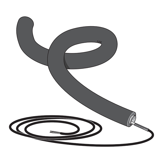
Different versions of KVR 11 KVR 11 is available in three lengths. Here you can see an ex- ample of the installation length. Installationslängd Installation length F2120 / S2125 KVR 11 KVR 11 2x230V Part No. Part No. Hose length 1 metre (installation length 1 m without water seal) -
Page 7: Pipe Connections
(subject to local rules and regu- lations), stone caisson, gutter drainage or other frost free collection point. • When casting the base, the holes for KVR 11 must have an Water seal internal diameter of 110 mm. •... -
Page 8: Stone Caisson
Route the pipe downward from the air/water heat pump. • The condensation water pipe must have a water seal to prevent air circulation in the pipe. • The installation length can be adjusted by the size of the water seal. Chapter 3 | Pipe connections KVR 11... -
Page 9: Electrical Connection
All electrical connections must be carried out by an authorised electrician. EB14 F2120 / S2125 KVR 11 is connected to the base board AA2-X9 in Connecting automatic protection F2120 / S2125. The connection is fused with 250 mA via fuse F3 at the factory. - Page 10 Secure the insulation with a cable tie. 4. Route the heating cable through the condensation water connection on the rear of KVR 11. Pull the insulation down slightly. 8. Route the heating cable to the electrical connection. 5. Lay the heating cable and ensure that the marking on the heating cable is as close to the condensation water connection as possible.
- Page 11 10. Connect the cable as illustrated in "Electrical connec- tion", see page Electrical connection. (Check the fuse according to the table, see page "Fuse".) 11. Reinstall the side panel, the top insulation and the top panel. KVR 11 Chapter 4 | Electrical connection...
-
Page 15: Contact Information
Tel: +48 (0)85 66 28 490 Hannabadsvägen 5, 285 21 Markaryd Tel. +41 (0)58 252 21 00 biawar.com.pl Tel: +46 (0)433-27 30 00 info@nibe.ch info@nibe.se nibe.ch nibe.se For countries not mentioned in this list, contact NIBE Sweden or check nibe.eu for more information. - Page 16 WS release date: 2022-06-21 07:12 Publish date: 2022-07-05 09:04 This is a publication from NIBE Energy Systems. All product illustrations, facts and data are based on the available information at the time of the publication’s approval. NIBE Energy Systems makes reservations for any factual or printing errors in this publication.
Need help?
Do you have a question about the KVR 11 and is the answer not in the manual?
Questions and answers