
Subscribe to Our Youtube Channel
Related Manuals for ASROCK SBC-262M-WT


Summary of Contents for ASROCK SBC-262M-WT
- Page 1 SBC-262M-WT User Manual Version 1.0 Published October 4, 2024 Copyright©2024 ASRockInd INC. All rights reserved.
-
Page 2: Copyright Notice
Version 1.0 Published October 4, 2024 Copyright©2024 ASRockInd INC. All rights reserved. Copyright Notice: No part of this documentation may be reproduced, transcribed, transmitted, or translated in any language, in any form or by any means, except duplication of documentation by the purchaser for backup purpose, without written consent of ASRockInd Inc. - Page 3 WARNING THIS PRODUCT CONTAINS A BUTTON BATTERY If swallowed, a button battery can cause serious injury or death. Please keep batteries out of sight or reach of children. CALIFORNIA, USA ONLY The Lithium battery adopted on this motherboard contains Perchlorate, a toxic substance controlled in Perchlorate Best Management Practices (BMP) regulations passed by the California Legislature.
- Page 4 *15G062470003AI* P/N: 15G062470003AI V1.2 Button Battery Safety Notice Button Battery Safety Notice WARNING • INGESTION HAZARD: This product contains a button cell or coin battery. • DEATH or serious injury can occur if ingested. • A swallowed button cell or coin battery can cause Internal Chemical Burns in as little as 2 hours.
-
Page 5: Table Of Contents
Contents Chapter 1 Introduction Package Contents Specifications Motherboard Layout I/O Panel Block Diagram Chapter 2 Installation Screw Holes Pre-installation Precautions Installation of Memory Modules (SO-DIMM) Expansion Slots Jumpers Setup Onboard Headers and Connectors Chapter 3 UEFI SETUP UTILITY Introduction 3.1.1 Entering BIOS Setup 3.1.2 UEFI Menu Bar... - Page 6 3.3.4 Super IO Configuration 3.3.5 ACPI Configuration 3.3.6 USB Configuration 3.3.7 Trusted Computing Hardware Health Event Monitoring Screen Security Screen Boot Screen Exit Screen...
-
Page 7: Chapter 1 Introduction
If you require technical support related to this motherboard, please visit our website for specific information about the model you are using. https://www.asrockind.com/technical-support 1.1 Package Contents ASRockInd SBC-262M-WT Motherboard (3.5" SBC (5.8-in x 4-in x 1.03-in, 14.7 cm x 10.2 cm x 2.6 cm)) ASRockInd SBC-262M-WT Jumper Setting Instruction Gift Package:... -
Page 8: Specifications
1.2 Specifications Form 3.5" SBC (5.8-in x 4-in x 1.03-in, 14.7 cm x 10.2 cm x Dimensions Factor 2.6 cm) Intel® Amston Lake Processors Processor X7433RE, QC, Max Speed Up to 3.4GHz, 9W System BIOS AMI SPI 256 Mbit Technology Single Channel DDR5 4800 MHz Memory Capacity... - Page 9 SBC-262M-WT 4 x USB 2.0 (2 x 2.54 pitch header) COM3, COM4 (RS-232) COM1, COM2 (RS-232/422/485) GPIO 4 x GPI, 4 x GPO LVDS Internal Connector SATA PWR Output Speaker Header MIPI Camera Header 1 x M.2 (Key M, 2242/2280) with PCIe Gen3 x1...
-
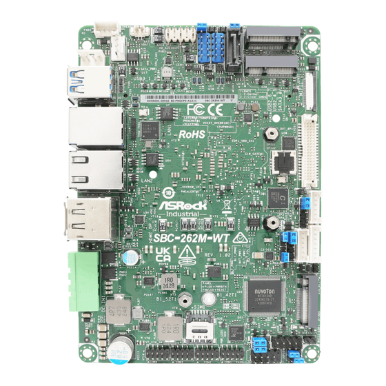
Page 10: Motherboard Layout
BAT1 SPEAKER1 HD_AUDIO1 SATA_PWR1 M2_E1 CPU_FAN1 USB2_6_7 USB2_ _ SATA3_0 USB 3.2 Gen2 MIPI1 Top: USB3_1 Bottom: USB3_2 LAN1 BIOS LAN2 HDMI SBC-262M-WT SIO_AT1 DC_IN1 M2_ 1 SIM1 PWR_ PWR_COM2 JGPIO1 BUZZ2 COM4 COM3 COM2 COM1 PLED PWRBTN JGPIO_SET1 HDLED... - Page 11 SBC-262M-WT Bottom : DDR5_A1 EDP1 BUZZ1 ESPI1...
- Page 12 1 : SATA Power Output Connector (SATA_PWR1) 2 : 2W Audio AMP Output Wafer (SPEAKER1) 3 : CPU FAN Connector (+12V) (CPU_FAN1) 4 : Battery Connector (BAT1) 5 : SATA3 Connector (SATA3_0) 6 : USB 2.0 Connectors (USB2_4_5, USB2_6_7) 7 : Front Panel Audio Header (HD_AUDIO1) 8 : DACC1 9 : Chassis Intrusion Header (CI1) 10 : Clear CMOS Headers (CLRMOS1, CLRMOS2)
-
Page 13: I/O Panel
SBC-262M-WT 1.4 I/O Panel USB 3.2 Gen2 (USB3_1) Phoenix Connector (DC_IN1) (9~36V)*** RJ45 2.5G LAN Port (LAN1)* HDMI Port (HDMI1) RJ45 1G LAN Port (LAN2)** USB 3.2 Gen2 (USB3_2) DisplayPort (DP) * There are two LEDs next to the LAN1 port. Please refer to the table below for the LAN1 port LED indications. -
Page 14: Block Diagram
1.5 Block Diagram SBC-262-WT DDIA Connector DDR5 4800MHZ SO-DIMM LVDS LVDS/eDP DDIB Chrontel connector CH7513A SATA3 SATA Port TCP0 DisplayPort PCIe Gen3 x1 HDMI TCP1 USB 2.0 connector M.2 Key E CNVi Rear 2 x USB 3.2 Gen2 2 x USB 3.2 Intel Gen2 2 x USB 2.0... -
Page 15: Chapter 2 Installation
SBC-262M-WT Chapter 2 Installation This is a 3.5" SBC (5.8-in x 4-in x 1.03-in, 14.7 cm x 10.2 cm x 2.6 cm) form factor mother- board. Before you install the motherboard, study the configuration of your chassis to ensure that the motherboard fits into it. -
Page 16: Installation Of Memory Modules (So-Dimm)
2.3 Installation of Memory Modules (SO-DIMM) SBC-262M-WT provides one 262-pin DDR5 (Double Data Rate 5) SO-DIMM slot, and supports Single Channel Memory Technology. Step 1. Align a SO-DIMM on the slot such that the notch on the SO-DIMM matches the break on the slot. -
Page 17: Expansion Slots
SBC-262M-WT 2.4 Expansion Slots There are three M.2 sockets and one SIM socket on this motherboard. M.2 sockets: 1 x M.2 (Key E, 2230) with PCIe Gen3 x1 and USB 2.0 for Wireless 1 x M.2 (Key B, 3042/3052) with PCIe Gen3 x1, USB 3.2 Gen1, USB 2.0 and SIM for 4G/5G 1 x M.2 (Key M, 2242/2280) with PCIe Gen3 x1 and SATA3 for SSD... -
Page 18: Jumpers Setup
2.5 Jumpers Setup The illustration shows how jumpers are setup. When the jumper cap is placed on pins, the jumper is “Short.” If no jumper cap is placed on pins, the jumper is “Open. ” The illustration shows a 3-pin jumper whose pin1 and pin2 are “Short”... - Page 19 SBC-262M-WT (2-pin CLRMOS2) Setting Description Open Normal (Default) (see p. 4, No. 10) Auto Clear CMOS Short When AC Power Off NOTE: CLRMOS2 allows you to clear the data in CMOS automatically when AC power on. The data in CMOS includes system setup information such as system password and system setup parameters.
- Page 20 ATX/AT Mode Jumper Setting Description Open ATX Mode (Default) (2-pin SIO_AT1) Short AT Mode (see p. 4, No. 22) COM Port Pin9 PWR Setting Jumpers Setting Description +5V (Default) (3-pin PWR_COM1 (For COM Port1)) +12V (3-pin PWR_COM2 (For COM Port2)) Open (see p.
-
Page 21: Onboard Headers And Connectors
SBC-262M-WT 2.6 Onboard Headers and Connectors Onboard headers and connectors are NOT jumpers. Do NOT place jumper caps over these headers and connectors. Placing jumper caps over the headers and connectors will cause per- manent damage of the motherboard! SATA Power Output Connector... - Page 22 SATA3 Connector Signal Name (7-pin SATA3_0) SATA-A+ (see p. 4, No. 5) SATA-A- SATA-B- SATA-B+ The Serial ATA3 (SATA3) connector supports SATA data cables for internal storage de- vices. The current SATA3 interface allows up to 6.0 Gb/s data transfer rate. USB 2.0 Connectors Signal Name Signal Name...
- Page 23 SBC-262M-WT MIPI Header Signal Name (22-pin MIPI1) I2C0_SDA (see p. 4, No. 13) I2C0_SCL CSI_E_D3_DP CSI_E_D3_DN CSI_E_D2_DP CSI_E_D2_DN CSI_E_CK_DP CSI_E_CK_DN CSI_E_D1_DP CSI_E_D1_DN CSI_E_D0_DP CSI_E_D0_DN LVDS Panel Connector Signal Name Signal Name LCD_VCC LCD_VCC (40-pin LVDS1) +3.3V LVDS_A_DATA0# (see p. 4, No. 14)
- Page 24 Inverter Power Control Wafer Signal Name (6-pin BLT_PWR1) (see p. 4, No. 19) BL CTL BL EN LCD_BLT_VCC LCD_BLT_VCC Backlight & Amp Volume Control Signal Name GPIO (7-pin BLT_VOL1) GPIO (see p. 4, No. 20) PWRDN BRIGHTNESS_UP BRIGHTNESS_DW Buzzer Header Signal Name BUZZ+ (2-pin BUZZ2)
- Page 25 SBC-262M-WT PWRBTN (Power Switch): Connect to the power switch on the chassis front panel. You may configure the way to turn off your system using the power switch. RESET (Reset Switch): Connect to the reset switch on the chassis front panel. Press the reset switch to restart the computer if the computer freezes and fails to perform a normal restart.
- Page 26 Back Side: ESPI Connector Signal Name (20-pin ESPI1) ESPI_CLK (see p. 5 No. 31) ESPI_CS# ESPI_RESET# ESPI_CS#1 The header is reserved for Port 80 code PLTRST# display and debugging purposes. COM_RST# ESPI_IO0 ESPI_IO1 ESPI_IO2 ESPI_IO3 ALERT#1 +3VSB Internal Use +5VSB ESPI_ALERT# EDP1 Signal Name...
-
Page 27: Chapter 3 Uefi Setup Utility
Chapter 3 UEFI SETUP UTILITY 3.1 Introduction ASRock Industrial UEFI (Unified Extensible Firmware Interface) is a BIOS utility which offers tweak-friendly options in an advanced viewing interface. The UEFI system works with a USB mouse and offers users a faster, sleeker experience. -
Page 28: Uefi Menu Bar
3.1.2 UEFI Menu Bar The top of the screen has a menu bar with the following selections: Main For setting system time/date information For advanced system configurations Advanced H/W Monitor Displays current hardware status Security For security settings Boot For configuring boot settings and boot priority Exit Exit the current screen or the UEFI Setup Utility Because the UEFI software is constantly being updated, the following UEFI setup... -
Page 29: Navigation Keys
SBC-262M-WT 3.1.3 Navigation Keys Use < > key or < > key to choose among the selections on the menu bar, and use < > key or < > key to move the cursor up or down to select items, then press <Enter>... -
Page 30: Main Screen
3.2 Main Screen When you enter the UEFI SETUP UTILITY, the Main screen will appear and display the system overview. Because the UEFI software is constantly being updated, the following UEFI setup screens and descriptions are for reference purpose only, and they may not exactly match what you see on your screen. -
Page 31: Advanced Screen
SBC-262M-WT 3.3 Advanced Screen I n t h i s s ec t ion, you may s et t he con f ig u r at ions for t he fol low i ng items: CPU Configuration, Chipset Configuration, Intel(R) Time Coordinated Computing, Storage... -
Page 32: Cpu Configuration
3.3.1 CPU Configuration Active Processor E-Cores Allows you to select the number of E-Cores to enable in each processor package. NOTE: Number of P-Cores and E-Cores are looked at together. When both are {0,0}, Pcode will enable all cores. CPU C States Support Allows you to enable CPU C States Support for power saving. - Page 33 SBC-262M-WT CFG Lock The option allows you to enable or disable the CFG Lock. Configuration options: [Enabled] [Disabled] Intel Virtualization Technology Intel Virtualization Technology allows a platform to run multiple operating systems and applications in independent partitions, so that one computer system can function as mul- tiple virtual systems.
-
Page 34: Power Limit
Power Limit 1 "Power Limit 1 in Milli Watts. BIOS will round to the nearest 1/8W when programming. 0 = no custom override. For 12.50W, enter 12500. Overclocking SKU: Value must be between Max and Min Power Limits (specified by PACKAGE_POWER_SKU_MSR). Other SKUs: This value must be between Min Power Limit and Processor Base Power (TDP) Limit. -
Page 35: Chipset Configuration
SBC-262M-WT 3.3.2 Chipset Configuration VT-d Intel® Virtualization Technology for Directed I/O helps your virtual machine monitor better utilize hardware by improving application compatibility and reliability, and provid- ing additional levels of manageability, security, isolation, and I/O performance. Configuration options: [Enabled] [Disabled]... - Page 36 Render Standby Power down the render unit when the GPU is idle for lower power consumption. Active LVDS Use this to enable or disable the LVDS. The default value is [Disabled]. Set the item to [Enabled]. Then press <F10> to save the setting and restart the system. Now the default value of Active LVDS is changed to [Enabled] (F9 load default is also set to [Enabled]).
- Page 37 SBC-262M-WT Restore on AC/Power Loss Allows you to select the power state after a power failure. [Power Off] sets the power to remain off when the power recovers. [Power On] sets the system to start to boot up when the power recovers.
- Page 38 3.3.3 Intel(R) Time Coordinated Computing #AC Split Lock Enable or Disable Alignment Check Exception (#AC). When enabled, this will assert an #AC when any atomic operation has an operand that crisses two cache lines. #GP Fault UC Lock Enable or Disable GP Fault Exception (GP#). When enabled, this will assert an GP# when encountering a Lock to un-cacheable memory before the bus is locked.
- Page 39 SBC-262M-WT GT CLOS The item enables or disables Graphics Technology(GT) Class of Service. Enable will reduce Gfx LLC allocation to minimize impact of Gfx workload on LLC.
-
Page 40: Storage Configuration
3.3.4 Storage Configuration SATA Controller(s) Allows you to enable or disable the SATA controllers. Configuration options: [Enabled] [Disabled] SATA Mode Selection AHCI: Supports new features that improve performance. Configuration option: [AHCI] Hybrid Storage Detection and Configuration Mode Hybrid Storage Detection and Configuration Mode allows you to select Hybrid Storage Detection and Configuration Mode. - Page 41 SBC-262M-WT Hard Disk S.M.A.R.T. S.M.A.R.T stands for Self-Monitoring, Analysis, and Reporting Technology. It is a monitoring system for computer hard disk drives to detect and report on various indica- tors of reliability. Configuration options: [Enabled] [Disabled]...
-
Page 42: Super Io Configuration
3.3.5 Super IO Configuration COM1 Configuration Use this to set parameters of COM1. Type Select Use this to select COM1 port type: [RS232], [RS422] or [RS485]. COM2 Configuration Use this to set parameters of COM2. Type Select Use this to select COM2 port type: [RS232], [RS422] or [RS485]. COM3 Configuration Use this to set parameters of COM3. -
Page 43: Acpi Configuration
SBC-262M-WT 3.3.6 ACPI Configuration Suspend to RAM Suspend to R A M a l lows you to select [Disabled] for ACPI suspend t y pe S1. It is recommended to select [Auto] for ACPI S3 power saving. Configuration options: [Auto] [Disabled]... -
Page 44: Usb Configuration
3.3.7 USB Configuration USB Power Control Use this option to control USB power. M.2 Key_B USB Function The item enables or disables M.2 Key_B USB function. -
Page 45: Trusted Computing
SBC-262M-WT 3.3.8 Trusted Computing NOTE: Options vary depending on the version of your connected TPM module. Security Device Support Security Device Support allows you to enable or disable BIOS support for security device. O.S. will not show Security Device. TCG EFI protocol and INT1A interface will not be available. -
Page 46: Pending Operation
Pending Operation Pending Operation allows you to schedule an Operation for the Security Device. NOTE: Your computer will reboot during restart in order to change State of the Device. Configuration options: [None] [TPM Clear] Platform Hierarchy This item allows you to enable or disable Platform Hierarchy. Configuration options: [Enabled] [Disabled] Storage Hierarchy This item allows you to enable or disable Storage Hierarchy. -
Page 47: Hardware Health Event Monitoring Screen
SBC-262M-WT 3.4 Hardware Health Event Monitoring Screen This section allows you to monitor the status of the hardware on your system, including the parameters of the CPU temperature, motherboard temperature, CPU fan speed, and the critical voltage. NOTE: Options vary depending on the features of your motherboard. -
Page 48: Security Screen
3.5 Security Screen In this section you may set or change the supervisor/user password for the system. You may also clear the user password. Supervisor Password Set or change the password for the administrator account. Only the administrator has authority to change the settings in the UEFI Setup Utility. Leave it blank and press enter to remove the password. -
Page 49: Boot Screen
SBC-262M-WT 3.6 Boot Screen This section displays the available devices on your system for you to configure the boot settings and the boot priority. Boot From Onboard LAN The item allows the system to be waked up by the onboard LAN. -
Page 50: Exit Screen
3.7 Exit Screen Save Changes and Exit When you select this option, the following message “Save configuration changes and exit setup?” will pop out. Press <F10> key or select [Yes] to save the changes and exit the UEFI SETUP UTILITY. Discard Changes and Exit When you select this option, the following message “Discard changes and exit setup?”...
Need help?
Do you have a question about the SBC-262M-WT and is the answer not in the manual?
Questions and answers