Advertisement
Quick Links
High-Efficiency Horizontal Discharge Variable Speed Heat Pump
!
Risk of fire
This unit uses a mildly flammable (A2L) refrigerant. Refer to A2L refrigerant safety consider-
ations in the Installation Manual to ensure safe installation, operation, and servicing of this unit.
Low-voltage wiring
JHE air handler
Thermostat
mitigation control
R
R
Control wiring diagram - standard ECM air handler and HH8 heat pump
Figure 1:
NOTICE
The mitigation control board has a bank of DIP switches. For use with a JHE air handler indoor
model, both DIP switches must be in the 0 or off position.
Mitigation control
Thermostat
R
R
A2L
Control wiring diagram - standard ECM gas furnace and HH8 heat pump
Figure 2:
NOTICE
The mitigation control board has a bank of DIP switches. Both DIP switches must be in the 1 or
on position. The room thermostat must control fossil fuel operation. W2 is applicable on only
multi-stage gas furnace models. Use the mitigation control A2L output instead of the G output for
Y81E, Z8ES, RL18,Y82E, Z8ET, Y91E, Z9ES, RG19, Y92E, and Z9ET gas furnace models.
Quick Reference Guide
CAUTION
JHE air handler
outdoor unit
harness leads
RED
YEL (Y2 IN)
YEL/BLK (Y1 OUT)
YEL (Y2 OUT)
YEL/BLK (Y1 IN)
WHT
ORG
BLU
HH8 heat pump
Furnace control
R
G
Y/Y2
Y/Y2
Y1
Note: Use the O terminal on the thermostat for the reversing valve connection (energized in cool-
ing mode). The room thermostat must control fossil fuel operation if matched with a gas furnace.
This equipment uses an inverter drive that stores hazardous energy up to 5 min after power is
removed. Wait for more than 5 min before performing electrical work after power is removed.
Clearance
During installation, maintain the required clearance from walls and adjacent equipment. See Figure
HH8 heat pump
3. When installing multiple units, be careful to avoid intake of discharged air from adjacent units.
Y/Y2
Y1
A2079-001
Minimum clearance
Figure 3:
Fasten this equipment to a sturdy base for protection against vibration, a strong breeze, or an
earthquake. Use anchors and a base adequate to protect the unit against tipping or dislocation.
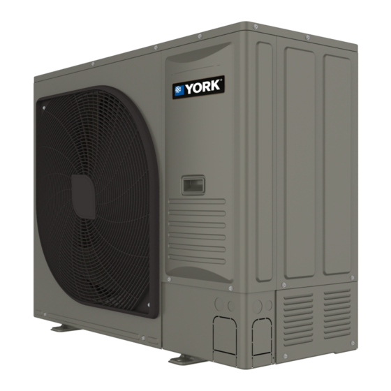
Connection and access points
Fan guard
(removable)
A2080-001
Mounting points
(4 points)
Figure 4:
Connection and access points
CAUTION
!
24k/36k: Over 12 in. (300 mm)
60k: Over 24 in. (600 mm)
Over 6 in.
(150 mm)
Over 20 in.
(500 mm)
NOTICE
High-voltage
connection
Low-voltage
connection
Vapor
connection
Service valve
connections
Over 8 in.
(200 mm)
Over 14 in.
(350 mm)
A2030-001
Liquid
connection
A2158-001
Advertisement

Related Manuals for York HH824E2S11


Summary of Contents for York HH824E2S11
- Page 1 Quick Reference Guide High-Efficiency Horizontal Discharge Variable Speed Heat Pump Note: Use the O terminal on the thermostat for the reversing valve connection (energized in cool- CAUTION ing mode). The room thermostat must control fossil fuel operation if matched with a gas furnace. CAUTION Risk of fire This unit uses a mildly flammable (A2L) refrigerant.
- Page 2 Attempting to braze a line under A1451-002 Electrical connections for HH824E2S11 models Figure 5: refrigerant pressure can cause the line to rupture. A rupture can propel hot solder and oil caus- ing injury to the technician attempting to braze the line.
Need help?
Do you have a question about the HH824E2S11 and is the answer not in the manual?
Questions and answers