Table of Contents
Advertisement
Quick Links
STUDIOMASTER PROFESSIONAL SERVICE MANUAL
AUDIOPLUS: A1, A2, GIRIRAJ INDUSTRIAL ESTATE, MAHAKALI CAVES ROAD, ANDHERI (EAST),
MUMBAI-400093, TEL No: 022-30880743, 30880749, 30880757.
Web site:- www.audioplus-india.com, www.studiomasterprofessional.com E mail:- support@audioplus-
india.com
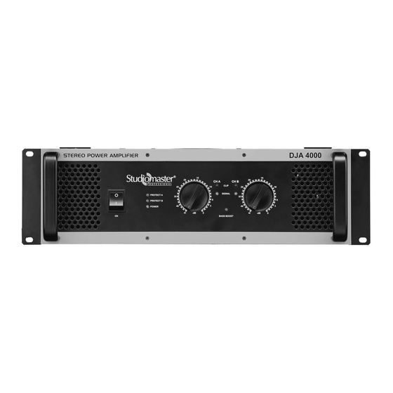
DJA2500/DJA4000
1
Advertisement
Table of Contents

Related Manuals for Studiomaster Professional DJA2500


Summary of Contents for Studiomaster Professional DJA2500
- Page 1 STUDIOMASTER PROFESSIONAL SERVICE MANUAL DJA2500/DJA4000 AUDIOPLUS: A1, A2, GIRIRAJ INDUSTRIAL ESTATE, MAHAKALI CAVES ROAD, ANDHERI (EAST), MUMBAI-400093, TEL No: 022-30880743, 30880749, 30880757. Web site:- www.audioplus-india.com, www.studiomasterprofessional.com E mail:- support@audioplus- india.com...
- Page 2 ...
-
Page 3: Table Of Contents
TABLE OF CONTENTS • INTRODUCTION ………………………………………………………………..…….4 • TOOLS & EQUIPMENTS REQUIRED………………………………………..………5 • SPECIFICATIONS………………………………………………………….…….…….6 • SAFETY INFORMATION……………………………………………….……….…….7 • AMPLIFIER BLOCK DIAGRAM……………………………………..…….………….8 • AMPLIFIER WIRING DIAGRAM………………………………….…………….……9 • DISASSEMBLY/ASSEMBLY PROCEDURE………………………….……….…..11 • TEST PROCEDURES…………………………………………………….…………….17 • COMPONENT PIN CONFIGURATION…………………………….…………………26 • TROUBLESHOOTING & FAULT CHART……………………………………………27 •... -
Page 4: Introduction
The information presented in this manual is intended for competent technical personnel to carry out service and product support for the Studiomaster Professional DJA series Amplifiers who is familiar to these amplifiers and who has knowledge related to electronic theory, and is able to carry out servicing, fault finding and repair of this amplifier series. -
Page 5: Important Note
TOOLS AND EQUIPMENT REQUIRED 1. Multi-bit screwdriver set, M3, M4 & M17 Spanner and good quality hand tools. 2. A set of short medium bristled artist or horsehair brushes. 3. Methanol alcohol or a non-corrosive, non-lubricant solvent. 4. Digital multimeter with a 20 kHz bandwidth. 5. -
Page 6: Specifications
SPECIFICATIONS DJA4000 DJA2500 Output Power Continuous Power @ 1% THD Single Channel 4Ω, 1x 1100W RMS 4Ω, 1x 1700W RMS 8Ω, 1x 700W RMS 8Ω, 1x 1000W RMS Stereo 4Ω, 2x 900W RMS 4Ω, 2x 1400W RMS 8Ω, 2x 600W RMS 8Ω, 2x 900W RMS... -
Page 7: Safety Information
SAFETY INFORMATION 1. Parts that have special safety characteristics are identified by the symbol On schematics or by special notes on the parts list. Use only replacement parts that have critical characteristics recommended by the manufacturer. 2. Make leakage current or resistance measurements to determine that exposed parts are acceptably insulated from the supply circuit before returning the unit to the customer. -
Page 8: Amplifier Block Diagram
AMPLIFIER BLOCK DIAGRAM ... -
Page 9: Amplifier Wiring Diagram
AMPLIFIER WIRING DIAGRAM ... - Page 10 ...
-
Page 11: Disassembly/Assembly Procedure
3.1 Perform procedure 1. 3.2 Disconnect the wire looms going to power amp pcb. 3.3 Remove bottom heatsink fitting screws M4X10 Self Tap Black. (DJA2500 – 3 nos/heatsink, DJA4000 – 5 nos./heatsink) 3.4 Lift the board upward carefully. 4. Power Amplifier PCB Replacement 4.1 Re-connect the wire harness as mentioned in 3.2. - Page 12 Screws from bottom side Screws from bottom side 5.0 PSU PCB removal Perform procedure 1. 5.2 Disconnect the wire harness going from PSU to Power amp, Input board, Output board, Front Control board & Transformer. Also remove fan tunnel. 5.3 Remove 4 X M3X6 Pan Head Black Machine screws fitted at corners. 5.4 Lift the board upward carefully.
- Page 13 7.0 Input PCB removal Perform procedure 1. 7.2 Remove M3X6 Pan Head Black Machine screws (2 nos.) fitted from inside. 7.3 Remove XLR to chassis screws M3X8 Pan Head Self Tap screws (qty 4 nos.), jack nuts (2 nos.) on rear. 7.4 Push the board backward and lift it carefully.
- Page 14 Transformer Mtg. screws DJA2500 DJA4000 11.0 LED PCB (DJA2500) removal 11.1 Perform procedure 1. 11.4 Disconnect the wire harness going to Led pcb. 11.5 Remove mounting screws M3X6 Pan Head Machine screws (qty 2 nos.) 11.6 Push the board backward & then lift it upward carefully.
- Page 15 Binding Post soldering leads 16.0. Fan Removal 16.1 Perform procedure 1. 16.2 For DJA2500, remove bottom screws M4X10 Self Tap Black screws black (4nos.) & in DJA4000, remove rear screws M4X10 Self Tap Black screws black (8nos.) 16.3 Lift the fan upward. .
- Page 16 18.0 Transformer Removal 18.1 Perform procedure 1. 18.2 Remove all transformer connections. 18.3 Remove transformer mounting hex Bolt & plain washer from chassis bottom. 18.4 Remove transformer by lifting it upward. 19.0 Transformer Replacement 19.1 Place the transformer in the chassis & align mounting hole. 19.2 Fit bottom bolt &...
-
Page 17: Test Procedures
Switch on the power supply. Mains voltage: 240V, 50Hz. Check that mains voltage is not less than 175V If there is no loading then switch Variac to parallel mode. Check the AC/DC voltages as mentioned below. DJA2500: AC VOLATGES A) AC1, AC5: 13V B) AC2: 88V... - Page 18 E) DC2, DC4: HV= +/-143V, LV=+/-70V F) DC3: +/- 11.7V Switch off the mains supply. B. AMPLIFIER UNIT TEST PROCEDURE DJA2500 Select the Amplifier in pre setting using switch on the Back plate. Amplifier in Stereo Mode. CROSSOVER/LOWCUT switch in OFF position.
- Page 19 4 Ω 8 Ω Stereo Mode Dual Channel Driven Both channels driven in various conditions Gain pot MAX. Feed 1KHz signal & adjust output at just clipping level. Power Output in V Load Ch 1 Ch 2 4 Ω 8 Ω III.
- Page 20 Connect the amplifier in stereo mode with 4Ω loads at 1 kHz. Drive single channel, Put the switch @ the rear into subwoofer mode Feed input to Left channel at rated sensitivity and Set output to 30V at 10Hz @ 4Ω loads using gain control pot.
- Page 21 Stereo mode single channel driven at 4 ohms:- During short circuit test output signal reduces & becomes square wave. Primary current CH1 Primary current CH2 POWER(V) Before Before short After short After short short 9A(±0.5A) 4A(±0.5A) 9A(±0.5A) 4A(±0.5A) Bridge Mode @ 8 OHM LOAD Primary Current POWER(V) Before short...
- Page 22 should be 1.5V (±0.2V) measured. If not adjust preset on the power amp PCB to get 1.3V (±0.2V) AMP PERFORMANCE MEASUREMENT: SENSITIVITY Drive single channel into 4 ohms load in Stereo mode at 1 kHz. Increase the input to get 82V (1680 W) just clipped output. The input required to get 82V output is the rated sensitivity.
- Page 23 Load connected to Bridge connector with load as specified. Channel 1 control MAX. Bridge mode selected from the Back Plate mode selection switch. Power Output Load 8 Ω 150V SIGNAL TO NOISE LEVEL MEASUREMENT: Connect the Amplifier in Stereo Mode with 4 Ω loads. Check the output power level with the given frequency filters and observe the readings for both the channel.
- Page 24 Output boost to 30V (+/-1V) X TALK MEASUREMENT: Connect the amplifier in stereo mode with 4Ω loads at 1 kHz. Connect input to both the channel feeding input of rated sensitivity. Set the gain pot of both the channels to MAX position. Set output to 66V. Feed input to channel 1KHz and take readings of the both channel.
- Page 25 FAN TEST FAN speed increases when the temperature on the heat-sink goes above 60 °C. BURN IN TEST. Settings: Amplifier in stereo mode with music signal, output clipping level driven into 4 ohm load. Observe that amplifier doesn’t go in to protect even after 4 hrs. Factory settings.
-
Page 26: Component Pin Configuration
COMPONENT PIN CONFIGURATION IC 4558 /LM358 2. IC 7812/7912 3. Bridge Rectifier 4. Transistor 2SA1943 CO LLE CTO R BASE E MITTE R 2SA1943 5. Transistor 2SC5200 6. 2SA1837/2SC4793 CO LLE CTO R BASE E MITTE R... -
Page 27: Troubleshooting & Fault Chart
TROUBLESHOOTING Fault Possible Causes/Rectification • Make sure the power cord is securely seated in the IEC socket and plugged all the way into the AC outlet. • Make sure the AC outlet is live (check with a tester or lamp). •... - Page 28 • Check the polarity of the speaker cable connections. You may have your positive and negative reversed at one end of one speaker cable. • Make sure the Clip LEDs are not lighting continuously. If so, turn down the Poor Bass response signal source or the amp Level controls.
-
Page 29: Spares List
Chassis Power cord Front Panel Power Switch Chassis Input Board Chassis DJA2500 Mains transformer Chassis DJA2500 Power Supply (PSU) Board Chassis DJA2500 Power Amp Module Front Panel DJA2500 Led/Control Board Chassis DJA2500 Output Board Chassis Power cord for DJA4000 Chassis... -
Page 30: Pcb Layouts
LAYOUTS & LEGENDS Input Pcb ... - Page 31 DJA2500 Led-Control Pcb DJA4000 Led-Control Pcb ...
- Page 32 DJA2500 Output Pcb DJA4000 Output Pcb ...
- Page 33 Power Amp Pcb DJA2500 DJA4000 33 ...
-
Page 34: Schematics With Ac & Dc Volatges
PCB SCHEMATICS Input Pcb 34 ... - Page 35 LED & OUTPUT Pcb 3. DJA2500 PSU 35 ...
- Page 36 4. DJA400 PSU 5. DJA2500 Power Amp 36 ...
- Page 37 6. DJA4000 Power Amp 37 ...
- Page 38 A1 & A2, Giriraj Ind. Estate, Mahakali Caves Road, Andheri (E), Mumbai-400093 (India). Phone.: +91-22-4286 9000 / 4286 9001 Fax +91-22-26871453 E-mail: info@audioplus-india.com Studiomaster Professional reserves the right to make modification to its manual without notice. REV. 001/DJA2500_4000 SERVICE/AUG 2013 ...
Need help?
Do you have a question about the DJA2500 and is the answer not in the manual?
Questions and answers