Table of Contents
Advertisement
Quick Links
Index
1...........................................................................................................................................................................................Warranty Information
2...........................................................................................................................................................................................................Introduction
3...........................................................................................................................................................................................Features at a Glance
4...........................................................................................................................................................................Front & Rear Panel Description
5..............................................................................................................................................................................................Wiring Information
6..............................................................................................................................................................................................System Application
7......................................................................................................................................................................................................Block Diagram
8...................................................................................................................................................................................Protections & Installations
9.................................................................................................................................................................................................Trouble Shooting
10.....................................................................................................................................................................................Technical Specifications
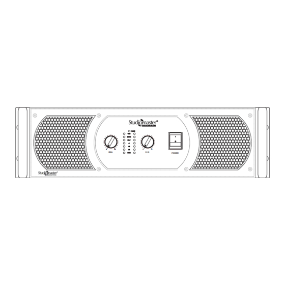
XPA Series
Professional Power Amplifier
TMS
MUTE
CILP
-10
0
0
10
10
-20
CH A
CH A
SIGN
Models: XPA 30, 40, 60
BASS
-3
0
10
CH B
POWER
Advertisement
Table of Contents

Related Manuals for Studiomaster Professional XPA Series


Summary of Contents for Studiomaster Professional XPA Series
- Page 1 XPA Series Professional Power Amplifier BASS MUTE CILP CH A CH A CH B SIGN POWER Models: XPA 30, 40, 60 Index 1......................................Warranty Information 2...........................................Introduction 3......................................Features at a Glance 4...................................Front & Rear Panel Description 5......................................Wiring Information 6......................................System Application 7........................................Block Diagram 8....................................Protections &...
-
Page 2: Important Safety Instructions
Explanation of Graphical Symbols CAUTION The lightning flash with arrowhead symbol within an equilateral triangle is intended to RISK OF ELECTRIC SHOCK alert the user to the presence of uninsulated DO NOT OPEN “dangerous voltage” within the product’s enclosure that may be of sufficient magnitude to constitute a risk of electric shock to persons. -
Page 3: For Safe Operation
Precautions For safe operation WARNING Do not modify the unit. Doing so is a re and electrical shock Installation hazard. If lightning begins to occur, turn off the power switch of the unit Connect this unit’s power cord only to an AC outlet of the type as soon as possible, and unplug the power cable from the electrical stated in this Owner’s Manual or as marked on the unit. -
Page 4: Warranty Information
Unpacking As part of our quality control system, every Studiomaster Professional product is thoroughly inspected before leaving the factory to ensure a flawless performance. After unpacking, please inspect the unit for any physical damages. In the event that a damage has occurred, kindly notify your Studiomaster Professional dealer immediately. -
Page 5: Signal & Clip Indicator
Signal & Clip Indicator These 4-segment Green LED lights show the output level of the amplifier. When the Clip LED turns Red, it means that the signal is distorting/clipping. Kindly reduce the output level from the mixer or other connected devices to avoid any damages. Bass/Boost Indicator This Red LED lights up when the Bass/Boost Function is activated or is in use. - Page 6 8 Sensitivity This switch is used to set the input sensitivity either at 0.775V or at 1.2V depending on the source. 9 Frequency Adjustment Knob When the filter switch is at SUB or at the LOW CUT position, use this knob to adjust the frequency. 10 Filter Switch Use this switch to select between the following two filter types.
- Page 7 6. System Application. Stereo Mode Configuration Output Connections ST & MO Mode BR Mode CH A only +1 = speaker + +1 = speaker + -1 = speaker - +2 = speaker - BASS/BOOST FREQUENCY (Hz) FREQUENCY (Hz) BRIDGE 0.775V 1.2V MONO BRIDGE...
- Page 8 Mono Mode Configuration Output Connections ST & MO Mode BR Mode CH A only +1 = speaker + +1 = speaker + -1 = speaker - +2 = speaker - BASS/BOOST FREQUENCY (Hz) FREQUENCY (Hz) BRIDGE 0.775V 1.2V MONO BRIDGE XPA 40 SENSITIVITY STEREO...
-
Page 9: Bridge: Mode Configuration
Bridge: Mode Configuration Output Connections ST & MO Mode BR Mode CH A only +1 = speaker + +1 = speaker + -1 = speaker - +2 = speaker - BASS/BOOST FREQUENCY (Hz) FREQUENCY (Hz) BRIDGE 0.775V 1.2V MONO BRIDGE XPA 40 SENSITIVITY STEREO... - Page 10 Stereo Mix Plus Subwoofer Configuration Output Connections ST & MO Mode BR Mode CH A only +1 = speaker + +1 = speaker + -1 = speaker - +2 = speaker - BASS/BOOST FREQUENCY (Hz) FREQUENCY (Hz) 0.775V 1.2V MONO BRIDGE BRIDGE XPA 40...
- Page 11 Stereo Mode: Cascade Configuration Output Connections ST & MO Mode BR Mode CH A only +1 = speaker + +1 = speaker + -1 = speaker - +2 = speaker - BASS/BOOST FREQUENCY (Hz) FREQUENCY (Hz) 0.775V 1.2V MONO BRIDGE BRIDGE XPA 40 SENSITIVITY...
- Page 12 Mono Mode - High Power Dual Channel Configuration AMPLIFIER 2 (Mono Mode) Output Connections ST & MO Mode BR Mode CH A only +1 = speaker + +1 = speaker + -1 = speaker - +2 = speaker - BASS/BOOST FREQUENCY (Hz) FREQUENCY (Hz) 0.775V...
- Page 13 Mono Mode + Subwoofer Configuration Output Connections ST & MO Mode BR Mode CH A only +1 = speaker + +1 = speaker + -1 = speaker - +2 = speaker - BASS/BOOST FREQUENCY (Hz) FREQUENCY (Hz) BRIDGE 0.775V 1.2V MONO BRIDGE XPA 40...
-
Page 14: Block Diagram
7. Block Diagram. -
Page 15: Overvoltage Protection
8. Protections & Installations. Thermal Protection 19” Rack Installation TMS (Thermal Management System) The amplifier is designed for use in a standard 19” rack This amplifier features an innovative temperature controlled with height of 3U units. gain variation technology called the Thermal Management System (TMS). -
Page 16: Troubleshooting
9. Trouble Shooting: Key to LED symbols: BLINKING GLOWING Indication Possible Reason 1. Normal operation BASS 1. The amplifier is in normal operation. MUTE CILP -3dB -10dB -20dB SIGN 1. Normal operation with TMS LED ON BASS 1.The amplifier is in normal operation. TMS LED shows gain is controlled due to increase in heatsink temperature. - Page 17 4. No Sound BASS 1. The amplifier goes in mute mode due to excessive input signal, speaker impedance mismatch or output short circuit. MUTE 2. Check the speaker impedance & speaker wiring for stray strands or breaks in the CILP insulation.
-
Page 18: Technical Specification
10. Technical Specification: Model XPA 30 XPA 40 XPA 60 2Ω (2 x 1500W RMS) 2Ω (2 x 2000W RMS) 2Ω (2 x 3000W RMS) Output power 4Ω (2 x 1100W RMS) 4Ω (2 x 1400W RMS) 4Ω (2 x 2000W RMS) Stereo @ THD 1% 8Ω... -
Page 19: For Your Records
For Your Records Model No............................● Serial No............................● Dealer’s Name..........................● Dealer’s Phone No........Fax No................● Date of Purchase..........................● Note... -
Page 20: Range Of Products
F15.40 FIRE 92 Kit Mini 6U PA 7.5 F15.50X S 9022 Mini 8 F15.40X S 9022 Kit Mini 8U ~ XPA Series F12.30X XPA 30 Stabilizers Passive Speakers ~ Air Series XPA 40 SVC - S1000 AiR 2 XPA 60...
Need help?
Do you have a question about the XPA Series and is the answer not in the manual?
Questions and answers