Table of Contents
Advertisement
Quick Links
Owner's Manual
I
POWER
O
POWER
I
O
POWER
I
O
DUAL CHANNEL
POWER AMPLIFIERS
DPA 2000
DPA 3200
DPA 4500
CH 1
-6
-10
-3
-15
-1
-30
-80
0dB
-6
-10
-3
CH 1
-15
-1
-30
-80
0dB
-6
-10
-3
CH 1
-15
-1
-30
-80
0dB
R
CH 2
PROTECT
-6
-10
-3
CLIP
-15
SIGNAL
-1
-30
-80
0dB
Class H Professional Power Amplifier
POWER
PROTECT
CLIP
SIGNAL
-6
-10
-3
POWER
-15
CH 2
-1
-30
Class H Professional Power Amplifier
-80
0dB
PROTECT
CLIP
SIGNAL
-6
-10
-3
POWER
-15
CH 2
-1
-30
Class H Professional Power Amplifier
-80
0dB
Advertisement
Table of Contents

Related Manuals for Studiomaster Professional DPA 2000


Summary of Contents for Studiomaster Professional DPA 2000
- Page 1 DUAL CHANNEL POWER AMPLIFIERS DPA 2000 DPA 3200 DPA 4500 Owner’s Manual CH 1 CH 2 PROTECT CLIP POWER SIGNAL Class H Professional Power Amplifier POWER PROTECT POWER CLIP SIGNAL POWER CH 1 CH 2 Class H Professional Power Amplifier...
- Page 2 Explanation of Graphical Symbols The lightning flash with arrowhead CAUTION symbol within an equilateral triangle is RISK OF ELECTRIC SHOCK intended to alert the user to the presence DO NOT OPEN of uninsulated “dangerous voltage” within the product’s enclosure that may be of sufficient magnitude to constitute a risk of electric shock to persons.
- Page 3 Precautions — — For safe operation WARNING Do not modify the unit. Doing so is a fire and electrical Installation shock hazard. If lightning begins to occur, turn off the power switch of Connect this unit’s power cord only to an AC outlet of the the unit as soon as possible, and unplug the power cable type stated in this Owner’s Manual or as marked on the unit.
- Page 4 Tips for Safe Operation The 3 core AC mains cable should be terminated with this For 2 ohm/4 ohm applications, it is recommended AC mains plug by connecting brown/red wire on live pin to use speakon connectors only. Use of cable 40/36 (L), black/blue wire on neutral pin (N) and yellow/green or thicker is recommended to prevent power wire on earth pin (E).
-
Page 5: Table Of Contents
Page No. Contents Features / General Description of Product..............6 Front Panel Controls & Features...................7 Rear Panel Controls & Features..................8 Input-Output Connections...................10 Setup & Operations.....................11 Typical Applications....................14 Protections & Installations..................17 Trouble Shooting......................18 Specifications......................20 Notes..........................23... -
Page 6: Features / General Description Of Product
5) Limiter 6) HF Limiter Twin tunnel cooling with front to back airflow. This owners Manual covers 4 models, DPA 2000, DPA 3200, DPA 4500 & DPA 5000 power amplifiers. Please read through this manual carefully before beginning use, so that you will be able to take full advantage of amplifier’s superlative features... -
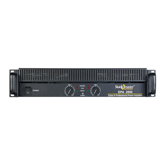
Page 7: Front Panel Controls & Features
CH 1 CH 2 PROTECT CLIP POWER SIGNAL Class H Professional Power Amplier POWER PROTECT POWER CLIP SIGNAL POWER CH 1 CH 2 Class H Professional Power Amplier Front Panel Controls & Features Master switch Switches the unit on and off, interrupting both phases. Power ON indicator light When lit, this blue LED indicates that amplifier is ON. -
Page 8: Rear Panel Controls & Features
DPA-2000 0 9 0 3 0 1 0 8 0 LIMITER INPUT 30Hz GROUND PROTECTION LOWCUT LIFT DPA-3200,4500 & 5000 LIMITER INPUT 30Hz GROUND LOWCUT PROTECTION LIFT 0 9 0 3 0 1 0 8 0 Rear Panel Controls & Features Balanced XLR input This XLR connector takes the signal (balanced/unbalanced) for driving the channel. - Page 9 10 Sensitivity This switch is used to select sensitivity to either 0.775V, 1V or 1.2V depending on the source. 11 Ground lift Allows circuit & chassis grounds to be separated in case of ground loops. 12 Low cut Low cut switch filters the low frequencies from the input signal. Cut off frequency is 30 Hz when it is selected. The filter protects the cone of the speakers against unwanted and inaudible low frequencies.
-
Page 10: Input-Output Connections
Input-Output Connections FIG. 1 FIG. 2 BALANCED INPUT CONNECTIONS UNBALANCED INPUT CONNECTIONS FIG. 3 FIG. 4 BRIDGE OUTPUT CONNECTIONS PARALLEL / STEREO OUTPUT CONNECTIONS (CH 1 OUTPUT CONNECTOR) FIG. 5 FIG. 6 PARALLEL / STEREO BINDING POST CONNECTIONS BRIDGE MODE BINDING POST CONNECTIONS -VE OUTPUT -STEREO -STEREO... -
Page 11: Setup & Operations
Setup & Operation Stereo Mode Configuration 0 9 0 3 0 1 0 8 0 SPEAKER SYSTEM SPEAKER SYSTEM LIMITER (IMP 8Ω / 4Ω / 2Ω) (IMP 8Ω / 4Ω / 2Ω) INPUT 30Hz GROUND PROTECTION LOWCUT LIFT MICROPHONES WIRELESS MICROPHONE SERIES CD PLAYER... - Page 12 Setup & Operation Parallel Mode Configuration 0 9 0 3 0 1 0 8 0 SPEAKER SYSTEM SPEAKER SYSTEM (IMP 8Ω / 4Ω / 2Ω) LIMITER (IMP 8Ω / 4Ω / 2Ω) INPUT 30Hz GROUND PROTECTION LOWCUT LIFT MICROPHONES ‘Y’- Cable WIRELESS MICROPHONE SERIES...
- Page 13 Setup & Operation Bridge Mode Configuration 0 9 0 3 0 1 0 8 0 SPEAKER SYSTEM LIMITER (IMP 8Ω / 4Ω) INPUT 30Hz GROUND PROTECTION LOWCUT LIFT MICROPHONES ‘Y’- Cable WIRELESS MICROPHONE SERIES CD PLAYER P A MIXER Note:- ‘Y’ cable to be used to make mono cable or use mono output of mixer. For BRIDGE mode operation, the signal source should be connected to the balanced / unbalanced inputs of channel 1 only.
-
Page 14: Typical Applications
Typical Applications Stereo Mix Plus Subwoofers AMPLIFIER 1 (Stereo Mode) (Fullrange (Fullrange 2/3 way system) 2/3 way system) 0 9 0 3 0 1 0 8 0 LIMITER INPUT 30Hz GROUND PROTECTION LOWCUT LIFT AMPLIFIER 2 (Bridge Mode) 0 9 0 3 0 1 0 8 0 LIMITER INPUT 30Hz... - Page 15 Typical Applications Stereo Mode - Cascade Configuration AMPLIFIER 2 (Stereo Mode) (Resultant Imp = not < 2Ω) (Resultant Imp = not < 2Ω) 0 9 0 3 0 1 0 8 0 LIMITER INPUT 30Hz GROUND PROTECTION LOWCUT LIFT (Resultant Imp = not < 2Ω) (Resultant Imp = not <...
- Page 16 Typical Applications Parallel Mode - High Power Dual Channel Configuration SPEAKER SPEAKER AMPLIFIER 2 (Parallel Mode) 0 9 0 3 0 1 0 8 0 LIMITER INPUT 30Hz GROUND PROTECTION LOWCUT LIFT LEFT BACK SPEAKER SPEAKER AMPLIFIER 1 (Parallel Mode) 0 9 0 3 0 1 0 8 0 LIMITER INPUT...
-
Page 17: Protections & Installations
19” Rack Installation The amplifier is designed for use in a standard 19” rack with height of 2U units (DPA 2000) and 3U units (DPA 3200, DPA 4500 & DPA 5000). In order to provide sufficient support base to the heavy amplifier, it is essential to use the 19”... -
Page 18: Trouble Shooting
Trouble Shooting Key to LED symbols: GLOWING BLINKING Indication: PROTECT CLIP SIGNAL POWER Condition: Normal operation Possible Reason: The amplifier is in normal operation Indication: PROTECT CLIP SIGNAL POWER Condition: No power to the amplifier Possible Reason: The amplifier power switch may be off. The amplifier may not be plugged into the power receptacle. Confirm that the AC outlet works by plugging in another device. - Page 19 Indication: PROTECT CLIP SIGNAL POWER Condition: Distorted Sound Possible Reason: The input signal level may be too high. So turn down the amplifier level controls. Check the level of the input source. If it is high then reduce the input signal level. The amplifier should never be operated at a level which causes the CLIP LED to illuminate constantly.
-
Page 20: Specifications
Specifications MODELS DPA 2000 DPA 3200 DPA 4500 Output power 2Ω 2 x 1040 W RMS 2Ω 2 x 1600W RMS 2Ω 2 x 2200W RMS Stereo @ THD 1% 4Ω 2 x W RMS 4Ω 2 x 1200W RMS 4Ω... - Page 21 Other Recommended Studiomaster Professional Products: Wired Microphones: • SM100XLR • SM200XLR • SM500XLR Wireless Microphones: • MR 12 Series: • GR Series • DR Series • KR Series • AR Series • ER 11 Series • ER 58 Series • BR 12 Series •...
- Page 22 Power Supply Stabilizers: • SVC – S1000 • SVC – S2000 • SVC – S3000 • SVC – S5000 • SVC – S8000 Processors: • SEQ 152 – Dual 15 Band Graphic Equalizer • Multi III – 8-Channels Splitter / Mixer / DI Box •...
-
Page 23: Notes
Notes... - Page 24 For Your Records Model No............................... Serial No..............................Dealer’s name............................Dealer’s Phone No............Fax No............Date of Purchase............................ *Design and specification are subject to change without notice is a registered trademark of Audioplus in India. © Copyright Audioplus, 2008. All rights reserved. Any unauthorised reproduction or use of logos, images or design elements is strictly prohibited by law.
Need help?
Do you have a question about the DPA 2000 and is the answer not in the manual?
Questions and answers
Dpa 3200 ka daigram