
Related Manuals for Tenmars TM-2012


Summary of Contents for Tenmars TM-2012
- Page 1 TM-2012/3012 AC CLAMP METER TM-2013/3014 AC/DC CLAMP METER User’s manual HB2TM2012001 TENMARS ELECTRONICS CO., LTD...
-
Page 2: Table Of Contents
TM- 2012/2013/3012/3014 CONTENTS: 1. SAFETY PRECAUTIONS AND PROCEDURES ......4 2. THE FOLLOWINGS SYMBOLS ARE USED: .......5 2.1. Preliminary..................5 2.2. During Use ..................6 2.3. After Use..................7 2.4. DEFINITION OF MEASURING (OVERVOLTAGE) CATEGORY ……………………………………………………………………..7 3. GENERAL DESCRIPTION............8 4. PREPARATION FOR USE............9 4.1. - Page 3 TM- 2012/2013/3012/3014 8. WAVEFORM COMPARISON............15 9. DESCRIPTION OF ROTARY SWITCH FUNCTIONDC....16 9.1. dc CURRENT (DCA) measurement of (TM-3014/TM-2013) ..16 9.2. AC Current (ACA) measurement..........17 9.3. AC Voltage (ACV) measurement..........19 9.4. DC Voltage (DCV) measurement..........20 9.5. RESISTANCE MEASUREMENT ..........21 9.6.
-
Page 4: Safety Precautions And Procedures
TM- 2012/2013/3012/3014 1. SAFETY PRECAUTIONS AND PROCEDURES This apparatus conforms to safety standard EN 61010, relating to electronic measuring instruments. For your own safety and that of the apparatus, you must follow the procedures described in this instruction manual and especially read all the notes proceeded by the symbol carefully. -
Page 5: The Followings Symbols Are Used
CAT IV 600 V, CAT III up to 1000 voltage between Phase and Earth (fixed installations) and for current measures up to CATIII 1000V/660A and CAT IV 600V/660A for (TM-2012/2013) and CAT III 1000V/1200A CATIV 600V/1200A for (TM-3012/TM- 3014)。... -
Page 6: During Use
TM- 2012/2013/3012/3014 • Do not perform any test with environmental condition exceeding the limits indicated in paragraphs 13.1.1 • Check if the batteries are installed correctly. • Prior to connecting the test probes to the installation, check that the function selector is positioned on the required measurement. -
Page 7: After Use
TM- 2012/2013/3012/3014 2.3. AFTER USE • Once the measurements are completed, turn the rotary switch to OFF. • If the instruments is not be used for a long period, remove the battery. 2.4. DEFINITION OF MEASURING (OVERVOLTAGE) CATEGORY The norm EN 61010: Safety requirements for electrical equipment for measurement, Control and laboratory use, Part 1: General requirements, defines what a measuring... -
Page 8: General Description
TM- 2012/2013/3012/3014 that reason, the norm requires that the transient withstand capability of the equipment is made known to the user. 3. GENERAL DESCRIPTION Dear customer, we thank you for your patronage. The clamp you have just purchased will grant you accurate and reliable measurements provided that it is used according to the present manual’s instructions. -
Page 9: Preparation For Use
TM- 2012/2013/3012/3014 4. PREPARATION FOR USE 4.1. INITIAL All the equipment has been checked mechanically and electrically prior to shipment. Every care has been taken to ensure that the instrument reaches you undamaged. However, it is wise to carry out a rapid check in order to detect any possible damage, which might have been caused during transport. -
Page 10: Storage
TM- 2012/2013/3012/3014 4.4. STORAGE In order to guarantee the accuracy of the measurements, after a period of storage in extreme environment condition, wait for the time necessary so that the apparatus returns to normal measuring conditions (see environments specifications paragraph 18.1.1. 5. -
Page 11: Alignment Marks
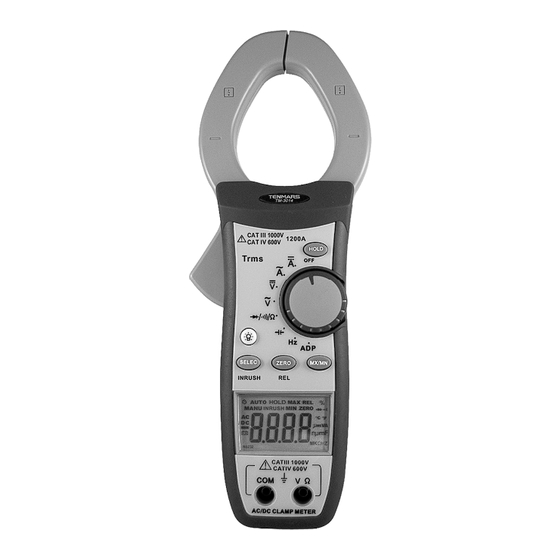
TM- 2012/2013/3012/3014 Fig. 1: Instrument description 5.1.2.Alignment marks Put the conductor within the jaws on intersection of the indicated marks as much as possible (see Fig. 2) In order to meet the meter accuracy specifications. LEGEND: 1. Alignment marks. 2. Conductor. Fig. -
Page 12: Auto Power Off Function
TM- 2012/2013/3012/3014 5.1.3.AUTO POWER OFF function 1. In order to save the battery the clamp will be switched off 30 minutes later last selecting a function or changing range operation. 2. If this function is enabled the symbol is displayed. 3. -
Page 13: Hold Key: Hold Function
TM- 2012/2013/3012/3014 This function can’t be enabled if the functions HOLD are already selected. Pressing the ZERO key the instrument will automatically set the MANUAL Range selection. 5.2.3.HOLD key: HOLD function The HOLD function allows operator to hold the displayed digital values. -
Page 14: True Rms Measurement
TM- 2012/2013/3012/3014 6. TRUE RMS MEASUREMENT The meter measures the true RMS value of AC voltages and currents. In physical terms, the RMS (root-mean-square) value of a waveform is the equivalent DC value that causes the same amount of heat to be dissipated in a resistor. True RMS measurement greatly simplifies the analysis of complex AC signals. -
Page 15: Waveform Comparison
TM- 2012/2013/3012/3014 8. WAVEFORM COMPARISON Table 1.illustrates the relationship between AC and DC components for common waveforms, and compares readings for true RMS meters and average-responding meters. For example, consider the first waveform, a 1.414V (zero-to-peak) sine wave. Both the RMS-calibrated average-responding meters display the correct RMS reading of 1.000V(the DC component equals 0). -
Page 16: Description Of Rotary Switch Functiondc
TM- 2012/2013/3012/3014 Triangle Sawtooth 3.464 1.732 0.962 1.000 0.000 1.000 (*) RMS CAL is the displayed value for average responding meter that are calibrated to display RMS for sine waves. Crest Factor = Peak value/True value 9. DESCRIPTION OF ROTARY SWITCH FUNCTIONDC 9.1. -
Page 17: Ac Current (Aca) Measurement
TM- 2012/2013/3012/3014 1. Set the rotary switch to A 2. Check if the display shows zero in advance. If the display doesn’t show zero, press ZERO key. 3. Open the clamp and put the tested conductor in the center of the clamp jaw taking care to comply with the current flow shown in the label placed inside the Inductive clamp jaw and indicates.FIG.3. - Page 18 TM- 2012/2013/3012/3014 Fig. 4: Use of clamp during AC current measurement 1. Set the rotary switch to A ~. 2. Open the clamp and put the tested conductor in the center of the clamp jaw. 3. The current value will be indicating on the display with automatic detection of the appropriate range.
-
Page 19: Ac Voltage (Acv) Measurement
TM- 2012/2013/3012/3014 9.3. AC VOLTAGE (ACV) MEASUREMENT WWARNING Maximum input for AC Voltage measurements is DC 1000V AC750Vrms. Do not attempt to take any voltage measurement that exceeds the limits. Exceeding the limits could cause electrical shock and damage the clamp meter. Fig. -
Page 20: Dc Voltage (Dcv) Measurement
TM- 2012/2013/3012/3014 9.4. DC VOLTAGE (DCV) MEASUREMENT WARNING Max. Input for DCV or ACV is DC 1000V AC750Vrms. Do not attempt to take any voltage measurement which exceeds the limits. Exceeding the limits could cause electrical shock and damage the clamp meter. Fig. -
Page 21: Resistance Measurement
TM- 2012/2013/3012/3014 5. If the reading is difficult, press the HOLD key to hold the obtained value. To exit from this function press HOLD key again. The analogy barograph isn’t affected of enabling of this function. 9.5. RESISTANCE MEASUREMENT WARNING Before taking any in circuit resistance measurement, remove power from the circuit being tested and discharge all the capacitors. -
Page 22: Diode Measurement
TM- 2012/2013/3012/3014 4. Connect the two long ends of test leads with the desired circuit, and then the reading will be displayed with automatic detection of the appropriate range. 5. If the reading is difficult, press the HOLD key to hold the obtained value. -
Page 23: Continuity Measurement
TM- 2012/2013/3012/3014 1. Set the rotary switch to /Ω. 2. Press the Inrush/select key to 3. Plug the test leads into the jacks. The red test lead plugs into V/Ω jack, and the black test lead plugs into COM jack. 4. -
Page 24: Frequency Measurements
TM- 2012/2013/3012/3014 1. Set the rotary switch to /Ω. 2. Press the Inrush/select key to 3. Plug the test leads into the jacks. The red test lead plugs into V/Ω jack, and the black test lead plugs into COM jack. 4. -
Page 25: Adp Measurements
TM- 2012/2013/3012/3014 1. Set the rotary switch to Hz. 2. Plug the test leads into the jacks. The red test lead plugs into V/Ω jack and the black test lead plugs into COM jack. 3. Connect the two long ends of test leads with the desired circuit, and then the reading will be displayed with automatic detection of the appropriate range. -
Page 26: Capacitance Measurements
TM- 2012/2013/3012/3014 1. Set the rotary switch to ADP. 2. Plug the test leads into the jacks. The red test lead plugs into V/Ω jack and the black test lead plugs into COM jack. 3. Connect the two long ends of test leads with the desired circuit, and then the reading will be displayed with automatic detection of the appropriate range. - Page 27 TM- 2012/2013/3012/3014 Fig. 11: Use of clamp for” Frequency” measures 1. Set the rotary switch to 2. Plug the test leads into the jacks. The red test lead plugs into V/Ω jack and the black test lead plugs into COM jack. 3.
-
Page 28: Preventive Maintenance
TM- 2012/2013/3012/3014 12. PREVENTIVE MAINTENANCE 12.1. GENERAL INFORMATION 1. This digital clamp meter is a precision instrument. Whether in use or in storage, please do not exceed the specification requirements to avoid any possible damage or danger during use. 2. Do not place this meter in high temperature or humidity or expose to direct sunlight. -
Page 29: Cleaning
DC Current of (TM-3014) Range Resolution Accuracy Overload Protection ± (1.5%+5) 660A 0.1A 1200A rms ( 60 second) ± (2.0%+5) 1200A AC Current of (TM-2012/TM-2013) Accuracy Range Resolution Overload Protection (50~60 Hz) ± 0.01A (2.0%+10) 660A rms ( 60 second) ± (2.0%+5) 660A 0.1A... - Page 30 TM- 2012/2013/3012/3014 DC Voltage Input Overload Range Resolution Accuracy impedance Protection 6.6V 11MΩ ±(0.5%rdg + 10mV 3 dgt) DC 1000V 660V 100mV AC750Vrms 10MΩ ±(0.8%rdg + 1000V 3 dgt) AC voltage Accuracy Overload Input (50 ~ Range Resolution Impedance Protection 500Hz) 6.6V 11MΩ...
- Page 31 TM- 2012/2013/3012/3014 Resistance Max. Open Overload Range Resolution Accuracy Loop protection voltage ±(1.0% rdg About 660Ω 0.1Ω 3.0VDC + 5 dgt) 6.6KΩ 1Ω ±(1.0% rdg 66 KΩ 10Ω DC 1000V AC750Vrms 660 KΩ 100Ω + 3 dgt) About 0.45VDC 6.6MΩ 1 KΩ...
-
Page 32: Safety
Pollution: Level 2 For inside use, maxes height: 2000m Over voltage: IEC61010-1 for CAT III 1000V CAT IV 600V IEC61010-2-032 for CATIII 1000V/660A and CAT IV600V/660A (TM-2012/2013) IEC61010-2-032 for CAT III 1000V/1200A and CATIV 600V/1200A (TM-3012/TM-3014) EN - 32... -
Page 33: General Data
TM- 2012/2013/3012/3014 17. GENERAL DATA Mechanical characteristics Jaws opening: 40mm(TM-2012/2013) 50mm (TM-3012/3014) Max conductor size: 42mm(TM-2012/2013) 52mm (TM-3012/3014) Supply Batteries type: V NEDA 1604 IEC 6F22JIS 006P battery x 1pc. Low battery indication: Symbol " " is displayed when battery level is too low. -
Page 34: Environmental Conditions
TM- 2012/2013/3012/3014 18. ENVIRONMENTAL CONDITIONS 18.1.1. Climatic conditions Reference temperature: 23° ± 5°C Operating temperature: 5 to 40 °C Operating humidity: <80% relative humidity for temperatures up to 31 °C decreasing linearly to 50% relative humidity at 40 °C. Storage temperature: -10 to 60 °C Storage humidity: 0 to 80% RH... - Page 36 Solar power meter, Radiation meter, Clamp meter, Multimeter Phase Rotation tester, Digital Insulation tester Our products of high quality are selling well all over the world TENMARS ELECTRONICS CO., LTD 6F, 586, RUI GUANG ROAD, NEIHU, TAIPEI 114, TAIWAN. E-mail: service@tenmars.com http://www.tenmars.com...
Need help?
Do you have a question about the TM-2012 and is the answer not in the manual?
Questions and answers