Table of Contents
Advertisement
Quick Links
TI01805F/00/EN/01.24-00
71670074
2024-09-01
Products
Technical Information
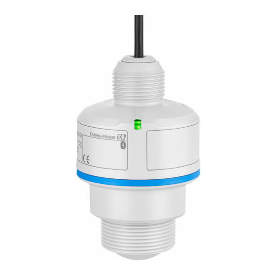
Micropilot FMR10B
Free-space radar
Level measurement in liquids and bulk solids
Application
• Continuous, non-contact level measurement of liquids and bulk solids
• Degree of protection: IP66/68 / NEMA Type 4X/6P
• Maximum measuring range up to 10 m (33 ft)
• Process temperature: –40 to 60 °C (–40 to 140 °F)
• Process pressure: –1 to 3 bar (–14 to 43 psi)
• Accuracy: Up to ± 5 mm (0.2 in)
Your benefits
• LED indicator for fast status detection
• Easy, guided commissioning with intuitive user interface
• Radar measuring device with Bluetooth® wireless technology
• Simple, safe and secure wireless remote access – ideal for installation in places
difficult to reach
• Commissioning, operation and maintenance via free iOS/Android app SmartBlue –
saves time and reduces costs
• Flow measurement in open channels or weirs with totalizer
Solutions
Services
Advertisement
Table of Contents

Related Manuals for Endress+Hauser Micropilot FMR10B


Summary of Contents for Endress+Hauser Micropilot FMR10B
- Page 1 Solutions Services TI01805F/00/EN/01.24-00 71670074 2024-09-01 Technical Information Micropilot FMR10B Free-space radar Level measurement in liquids and bulk solids Application • Continuous, non-contact level measurement of liquids and bulk solids • Degree of protection: IP66/68 / NEMA Type 4X/6P • Maximum measuring range up to 10 m (33 ft) •...
-
Page 2: Table Of Contents
Micropilot FMR10B Table of contents About this document ......4 Climate class ....... 19 Operating height . - Page 3 Micropilot FMR10B Documentation ......44 Standard documentation ......44 Supplementary device-dependent documentation .
-
Page 4: About This Document
Micropilot FMR10B About this document Symbols Safety symbols DANGER This symbol alerts you to a dangerous situation. Failure to avoid this situation will result in serious or fatal injury. WARNING This symbol alerts you to a dangerous situation. Failure to avoid this situation can result in serious or fatal injury. -
Page 5: Graphic Conventions
Micropilot FMR10B The term "operating tool" is used in place of the following operating software: • FieldCare / DeviceCare, for operation via HART communication and PC • SmartBlue app, for operation using an Android or iOS smartphone or tablet Programmable logic controller (PLC) Graphic conventions •... -
Page 6: Measuring System
Micropilot FMR10B ∆f = k ∆t where ∆t is the run time and k is the specified increase in frequency modulation. ∆t is given by the distance D between the reference point R and the product surface: D = (c ∆t) / 2 where c is the wave velocity. - Page 7 Micropilot FMR10B Maximum measuring range The maximum measuring range is 10 m (33 ft). Usable measuring range The usable measuring range depends on the medium' s reflective properties, the installation position and any possible interference echoes. In principle, measurement is possible up to the tip of the antenna.
- Page 8 • Relative permittivity (ε value), Compendium CP01076F • The Endress+Hauser "DC Values app" (available for Android and iOS) Measurement in storage vessel Storage vessel - measuring conditions Calm medium surface (e.g. bottom filling, filling via immersion tube or rare filling from above)
- Page 9 Micropilot FMR10B 40 mm (1.5 in) antenna in storage vessel Media group Measuring range A (ε 1.4 to 1.9) 10 m (33 ft) B (ε 1.9 to 4) 10 m (33 ft) C (ε 4 to 10) 10 m (33 ft) D (ε...
-
Page 10: Operating Frequency
Micropilot FMR10B Operating frequency approx. 80 GHz Up to eight devices can be installed in a tank without the devices mutually influencing one another. Transmission power • Peak power: <1.5 mW • Average output power: <70 µW Output Output signal •... -
Page 11: Totalizer
Micropilot FMR10B Linearization tables for calculating the volume in the following vessels are pre-programmed into the device: • Pyramid bottom • Conical bottom • Angled bottom • Horizontal cylinder • Sphere Linearization tables for calculating the flow rate are pre-programmed into the device and include the following: •... -
Page 12: Overvoltage Protection
Micropilot FMR10B Overvoltage protection The device satisfies the IEC/DIN EN 61326-1 product standard (Table 2 Industrial environment). Depending on the type of connection (DC power supply, input line, output line), different test levels are used to prevent transient overvoltages (IEC/DIN EN 61000-4-5 Surge) in accordance with IEC/DIN EN 61326-1: Test level for DC power supply lines and IO lines: 1 000 V wire to ground. -
Page 13: Influence Of Ambient Temperature
Micropilot FMR10B Differing values in near-range applications for liquids ∆ [mm (in)] 10 (0.39) 5 (0.2) -5 (-0.2) -10(-0.39) D [m ( )] 0.25 (0.8) A0055954 4 Maximum measurement error in near-range applications Δ Maximum measurement error Reference point of the distance measurement... -
Page 14: Response Time
Micropilot FMR10B Digital Average T = ±2 mm (±0.08 in)/10 K Analog (current output) • Zero point (4 mA): average T = 0.02 %/10 K • Span (20 mA): average T = 0.05 %/10 K Response time According to DIN EN IEC 61298-2 / DIN EN IEC 60770-1 , the step response time is the time following an abrupt change in the input signal up until the changed output signal has adopted 90 % of the steady-state value for the first time. -
Page 15: Mounting Location
Micropilot FMR10B Mounting location A0055811 Use of a weather protection cover; protection from direct sunlight or rain Installation in the center, interference can cause incorrect signal evaluation Do not install above the filling curtain Orientation Internal vessel fittings α A0031777 Avoid internal fittings (point level switches, temperature sensors, struts, vacuum rings, heating coils, baffles etc.) inside the signal beam. -
Page 16: Beam Angle
Micropilot FMR10B A0055958 7 Nozzle installation, 40 mm (1.5 in) antenna The maximum nozzle length L depends on the nozzle diameter D. Please note the limits for the diameter and length of the nozzle. 40 mm (1.5 in) antenna, installation outside nozzle •... -
Page 17: Flooding Protection Tube
Micropilot FMR10B A0055999 9 Weather protective cover, cable entry from above The sensor is not completely covered by the weather protective cover. Flooding protection tube The flooding protection tube ensures the sensor measures the maximum level even if it is completely flooded. -
Page 18: Cantilever Installation, With Pivot
Micropilot FMR10B A0056001 11 Installation with mounting bracket, adjustable Mounting bracket, adjustable for 40 mm (1.5 in) antenna, wall mounting Mounting bracket, adjustable for 40 mm (1.5 in) antenna, ceiling mounting • Wall or ceiling installation is possible. • Using the mounting bracket, position the antenna so that it is perpendicular to the product surface. -
Page 19: Mounting With A Pivotable Mounting Bracket
Micropilot FMR10B A0028412 13 Cantilever installation, with pivot Cantilever with wall bracket (side view) Cantilever with mounting frame (side view) Cantilever can be turned, e.g. in order to position the device over the center of the flume (top view) NOTICE There is no conductive connection between the mounting bracket and transmitter housing. -
Page 20: Degree Of Protection
Micropilot FMR10B Degree of protection Test as per IEC 60529 Edition 2.2 2013-08/DIN EN 60529 2014-09 and NEMA 250-2014: • IP66, NEMA Type 4X • IP68, NEMA Type 6P (24 h at 1.83 m (6.00 ft) under water) Vibration resistance •... -
Page 21: Process
• Contact Endress+Hauser for lower ε values For bulk solids ε ≥ 1.6 For applications with a lower relative permittivity than indicated, contact Endress+Hauser. For the relative permittivity values (ε values) of many media commonly used in industry, please refer to: • Relative permittivity (ε... -
Page 22: Mechanical Construction
Micropilot FMR10B Mechanical construction Dimensions 40 mm (1.5 in) antenna, cable entry from above 77 (3.03) 38.3 (1.51) A0055109 16 Dimensions; 40 mm (1.5 in) antenna with cable entry from above. Unit of measurement mm (in) Reference point of the measurement... -
Page 23: Materials
Micropilot FMR10B Materials A0056009 18 Overview of materials; 40 mm (1.5 in) antenna, cable entry thread Antenna end process connection; PVDF EPDM seal (for G 1½" thread) PBT/PC design ring PBT/PC sensor housing EPDM seal Cable entry process connection: PBT/PC Counter nut;... -
Page 24: Led Indicator
Operation via Bluetooth® wireless technology Prerequisite: Smartphone or tablet with Endress+Hauser SmartBlue app or PC with DeviceCare from version 1.07.07 or FieldXpert SMT70/SMT77 The connection has a range of up to 25 m (82 ft). The range can vary depending on environmental conditions such as attachments, walls or ceilings. -
Page 25: Certificates And Approvals
Micropilot FMR10B Certificates and approvals Current certificates and approvals for the product are available at www.endress.com on the relevant product page: Select the product using the filters and search field. Open the product page. Select Downloads. Radio standard EN 302729 The devices are approved for unrestricted use inside and outside closed containers in countries of the EU and the EFTA. -
Page 26: Fcc
Micropilot FMR10B Country Name of the station Latitude Longitude Spain Yebes 40° 31' 27" North 03° 05' 22" West Robledo 40° 25' 38" North 04° 14' 57" West Hungary Penc 47° 47' 22" North 19° 16' 53" East As a general rule, the requirements outlined in EN 302729 must be observed. -
Page 27: Identification
• Automatic verification of exclusion criteria • Automatic creation of the order code and its breakdown in PDF or Excel output format • Ability to order directly in the Endress+Hauser Online Shop Identification Measuring point (TAG) The device can be ordered with a tag name. -
Page 28: Securing Nut G 1½
Micropilot FMR10B 107.6 (4.24) 112.8 (4.44) A0055295 20 Dimensions for weather protective cover G1/NPT1, cable entry from above. Unit of measurement mm (in) Material PBT/PC Order code 71662413 Securing nut G 1½" Suitable for devices with G 1½" and MNPT 1½" process connection. -
Page 29: Uni Adapter G 1½">G 2
Micropilot FMR10B Material Order code 52000598 Uni adapter G 1½">G 2" Temperature range –40 to 45 °C (–40 to 113 °F) 40 (1.57) A0055848 23 Dimensions of Uni adapter Material Order code 71662415 Uni adapter MNPT 1½" > Temperature range –40 to 65 °C (–40 to 150 °F) MNPT 2"... -
Page 30: Mounting Bracket, Adjustable, Wall/Rope/Ceiling, 75 Mm
Micropilot FMR10B 60 (2.36) G1 1/2" 69 (2.72) A0055301 25 Flooding protection tube dimensions 40 mm (1.5 in). Unit of measurement mm (in) Material Order code 71091216 Mounting bracket, The mounting bracket can be used for mounting on a wall, a rope or a ceiling. -
Page 31: Mounting Bracket, Adjustable, Wall, 200 Mm
Micropilot FMR10B Antenna end process connection G 1½"/NPT 1½" 92.5 (3.64) 75 (2.95) 70 (2.76) 9 (0.35) 12 (0.47) 9 (0.35) A0055372 27 Dimensions of mounting bracket. Unit of measurement mm (in) Consists of: • 1 × mounting bracket, 316L (1.4404) •... -
Page 32: Angle Bracket For Wall Mounting
Micropilot FMR10B Antenna end process connection G 1½"/NPT 1½" 217.5 (8.56) 200 (7.87) 70 (2.76) 9 (0.35) 12 (0.47) 9 (0.35) A0055373 29 Dimensions of mounting bracket. Unit of measurement mm (in) Consists of: • 1 × mounting bracket, 316L (1.4404) •... -
Page 33: Cantilever, Pivotable
Micropilot FMR10B Cantilever, pivotable Installation type sensor cable entry process connection A0028885 31 Installation type sensor cable entry process connection Installation with cantilever and wall bracket Installation with cantilever and mounting frame Cantilever Wall bracket Mounting frame 500 mm cantilever with pivot, sensor cable entry process connection 585 (23) 35 (1.4) - Page 34 Micropilot FMR10B 1 000 mm cantilever with pivot, sensor cable entry process connection 1085 (42.7) 35 (1.4) 300 (11.8) 75 (2.9) 75 (2.9) 100 (3.9) 750 (29.5) 35 (1.4) A0037807 33 Dimensions of 1 000 mm cantilever with pivot, for sensor cable entry process connection. Unit of...
- Page 35 Micropilot FMR10B 500 mm cantilever with pivot, sensor antenna end process connection G 1½" 585 (23) 35 (1.4) 200 (7.87) 75 (2.9) 75 (2.9) 100 (3.9) 250 (9.84) 35 (1.4) A0037802 35 Dimensions of 500 mm cantilever with pivot, for sensor antenna end process connection G 1½". Unit of...
- Page 36 Micropilot FMR10B Weight: 4.4 kg (9.7 lb) Material 316L (1.4404) Order code 71452319 • 50 mm (2.17 in) openings for all G 1½" or MNPT 1½" antenna end thread process connections • 22 mm (0.87 in) opening can be used for any additional sensor •...
- Page 37 Micropilot FMR10B Mounting stand, 1 400 mm (55.1 in) for cantilever with pivot 3.2 (0.13) 60 (2.36) ø33.7 (1.3) 4 (0.16) 20 (0.8) 55 (2.17) 109 (4.29) (3.94) 130 (5.12) 150 (5.91) A0037800 38 Dimensions. Unit of measurement mm (in) Weight: 6 kg (13.23 lb)
-
Page 38: Pivotable Mounting Bracket
Micropilot FMR10B Pivotable mounting bracket The pivotable mounting bracket is used, for example, to install the device in a manhole over a sewer channel. 100 (3.94) 6.8 (0.27) 177 (6.97) 358 (14.1) A0038143 40 Dimensions of pivotable mounting bracket. Unit of measurement mm (in) 34 mm (1.34 in) openings for all G 1"... - Page 39 Micropilot FMR10B 15° 15° (0.39) <360 NPT ¾ (14.2) NPT 1 70 (2.76) 500 (19.7) (0.8) (1.18) 19 (0.75) A0045330 41 Dimensions. Unit of measurement mm (in) Welding flange UNI flange Material • Flange: 304 • Pipe: Steel, galvanized •...
-
Page 40: Uni Flange 2"/Dn50/50, Pp
Micropilot FMR10B UNI flange 2"/DN50/50, PP 120 (4.72) 125 (4.92) 165 (6.5) A0037946 42 Dimensions of UNI flange 2"/DN50/50. Unit of measurement mm (in) Sensor connection in accordance with the product structure "Antenna end process connection" Material Order code... -
Page 41: Uni Flange 3"/Dn80/80, Pp
Micropilot FMR10B UNI flange 3"/DN80/80, PP 150 (5.91) 160 (6.3) 200 (7.87) A0037947 43 Dimensions of UNI flange 3"/DN80/80. Unit of measurement mm (in) Sensor connection in accordance with the product structure "Antenna end process connection" or "Cable entry process connection"... -
Page 42: Uni Flange 4"/Dn100/100, Pp
Micropilot FMR10B UNI flange 4"/DN100/100, 175 (6.89) 190.5 (7.5) 228.6 (9.0) A0037948 44 Dimensions of UNI flange 4"/DN100/100. Unit of measurement mm (in) Sensor connection in accordance with the product structure "Antenna end process connection" or "Cable entry process connection"... -
Page 43: Adjustable Flange Seal
DeviceCare SFE100 Configuration tool for IO-Link, HART, PROFIBUS and FOUNDATION Fieldbusfield devices DeviceCare is available for download free of charge at www.software-products.endress.com. You need to register in the Endress+Hauser software portal to download the application. Technical Information TI01134S Device Viewer All the spare parts for the device, along with the order code, are listed in the Device Viewer (www.endress.com/deviceviewer). -
Page 44: Rn22
For an overview of the scope of the associated Technical Documentation, refer to the following: • Device Viewer (www.endress.com/deviceviewer): Enter the serial number from the nameplate • Endress+Hauser Operations app: Enter serial number from nameplate or scan matrix code on nameplate. Standard documentation Document type: Operating Instructions (BA) Installation and initial commissioning ‒... - Page 45 Micropilot FMR10B Bluetooth® The Bluetooth® word mark and logos are registered trademarks owned by the Bluetooth SIG, Inc. and any use of such marks by Endress+Hauser is under license. Other trademarks and trade names are those of their respective owners. Endress+Hauser...
- Page 48 *71670074* 71670074 www.addresses.endress.com...
Need help?
Do you have a question about the Micropilot FMR10B and is the answer not in the manual?
Questions and answers