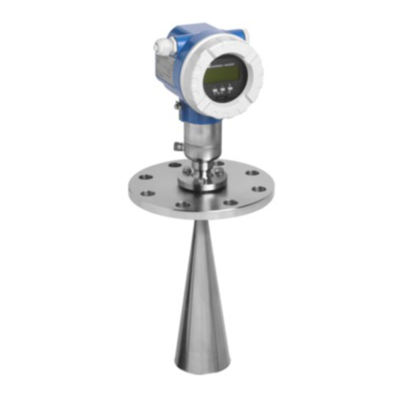
Endress+Hauser micropilot M FMR 240 Operating Instructions Manual
Profibus pa level-radar
Hide thumbs
Also See for micropilot M FMR 240:
- Technical information (44 pages) ,
- Operating instructions manual (88 pages)
Table of Contents
Advertisement
Quick Links
Download this manual
See also:
Technical Information
BA 227F/00/en/12.03
Nr. 52008596
Valid as of software version:
V 01.02.00 (amplifier)
V 01.02.00 (communication)
micropilot M
FMR 240
PROFIBUS PA
Level-Radar
Operating Instructions
E N
E N
D R
D R
M IC
M IC
E S
E S
O rd
O rd
e r
e r
R O
R O
S +
S +
H A
H A
S e
S e
C o
C o
P IL
P IL
r. -N
r. -N
d e :
d e :
U S
U S
o .:
o .:
O T
O T
E R
E R
II
II
M e
M e
s s b
s s b
M e
M e
e re
e re
a s u
a s u
ic h
ic h
ri n g
ri n g
ra n
ra n
g e
g e
U 1
U 1
m a
6 .. .3
6 .. .3
4 .. .2
4 .. .2
x . 2
6 V
6 V
0 m
0 m
0 m
D C
D C
A
A
IP
IP
6 5
6 5
T
T
A
A
> 7 0
> 7 0
°C
°C
:
:
t > 85
t > 85
°C
°C
Advertisement
Table of Contents

Subscribe to Our Youtube Channel
Related Manuals for Endress+Hauser micropilot M FMR 240


Summary of Contents for Endress+Hauser micropilot M FMR 240
- Page 1 micropilot M BA 227F/00/en/12.03 Nr. 52008596 Valid as of software version: FMR 240 V 01.02.00 (amplifier) V 01.02.00 (communication) PROFIBUS PA Level-Radar Operating Instructions M IC M IC O rd O rd P IL P IL r. -N r. -N d e : d e : o .:...
- Page 2 Micropilot M FMR 240 with PROFIBUS PA Brief operating instructions KA 159F/00/a2/05.02 Micropilot M - Brief operating instructions 52006292 Contrast: measured value dist./ meas value Group selection basic setup tank shape medium process empty full pipe dist./ check range of start cond.
-
Page 3: Table Of Contents
Designated use ......4 Contact addresses of Endress+Hauser ..95 Installation, commissioning and operation . . . 4 Operational safety . -
Page 4: Safety Instructions
Safety instructions Designated use The Micropilot M FMR 240 is a compact radar level transmitter for the continuous, contactless measurement of liquids, pastes and sludge. The device can also be freely mounted outside closed metal vessels because of its operating frequency of about 26 GHz and a maximum radiated pulsed energy of 1mW (average power output 1 µW). -
Page 5: Notes On Safety Conventions And Symbols
Micropilot M FMR 240 with PROFIBUS PA Safety instructions Notes on safety conventions and symbols In order to highlight safety-relevant or alternative operating procedures in the manual, the following conventions have been used, each indicated by a corresponding symbol in the margin. -
Page 6: Identification
Identification Micropilot M FMR 240 with PROFIBUS PA Identification Device designation 2.1.1 Nameplate The following technical data are given on the instrument nameplate: L00-FMR2xxxx-18-00-00-en-002 Fig. 1: Information on the nameplate of the Micropilot M with PROFIBUS-PA (example) 2.1.2 Ordering structure... - Page 7 Micropilot M FMR 240 with PROFIBUS PA Identification Ordering structure Micropilot M FMR 240 (continued) Type of antenna, sealing, temperature Type Sealing Temperature range V Standard Viton/FKM -20° C…150° C / -4 °F…+302 °F E Standard Viton GLT -40° C…150° C / -40 °F…+302 °F...
- Page 8 Identification Micropilot M FMR 240 with PROFIBUS PA Ordering structure Micropilot M FMR 240 (continued) Output and menu based operation A 4…20 mA HART with VU 331 (4-line alphanumeric display) B 4…20 mA HART K 4...20 mA HART, prepared for FHX40, mounting of remote display (accessory)
-
Page 9: Scope Of Delivery
"Protection Measures for Electrical Equipment for Measurement, Control, Regulation and Laboratory Procedures". The instrument described in this manual thus complies with the statutory requirements of the EG directives. Endress+Hauser confirms the successful testing of the instrument by affixing to it the CE mark. -
Page 10: Mounting
Mounting Micropilot M FMR 240 with PROFIBUS PA Mounting Quick installation guide Observe orientation when installing! Turn housing Installation in tank (free space): The housing can be turned 350° in order to simplify access to the Mark on process connector facing the nearest tank wall! -
Page 11: Incoming Acceptance, Transport, Storage
Micropilot M FMR 240 with PROFIBUS PA Mounting Incoming acceptance, transport, storage 3.2.1 Incoming acceptance Check the packing and contents for any signs of damage. Check the shipment, make sure nothing is missing and that the scope of supply matches your order. -
Page 12: Installation Conditions
Mounting Micropilot M FMR 240 with PROFIBUS PA Installation conditions 3.3.1 Dimensions Housing dimensions max. 110 ENDRESS+HAUSER F12 housing (Aluminium) L00-F12xxxx-06-00-00-en-001 max. 100 ENDRESS+HAUSER T12 housing (Aluminium) L00-T12xxxx-06-00-00-en-001 max. 94 F23 housing (316L) L00-F23xxxx-06-00-00-en-001 Endress + Hauser... - Page 13 Micropilot M FMR 240 with PROFIBUS PA Mounting Micropilot M FMR 240 - process connection, type of antenna F12 / T12 / F23 housing Threaded connection Flange DN 50…150 1 ½” BSPT (R 1 ½”) or equivalent or 1 ½ NPT 3"...
- Page 14 Mounting Micropilot M FMR 240 with PROFIBUS PA 3.3.2 Engineering hints Orientation • Recommended distance (1) wall – outer edge of nozzle: ~1/6 of tank diameter. Nevertheless the device should not be installed closer than 15 cm (6“) to the tankwall.
- Page 15 Micropilot M FMR 240 with PROFIBUS PA Mounting Beam angle The beam angle is defined as the angle a where the energy density of the radar waves reaches half the value of the maximum energy density (3dB-width). Microwaves are also emitted outside the signal beam and can be reflected off interfering installations.
- Page 16 Mounting Micropilot M FMR 240 with PROFIBUS PA Measuring conditions Note! Please use FMR 230 respectively FMR 231 for boiling surfaces or in case of a tendency for foaming. The maximum measuring range of the FMR244 may decrease in case of heavy steam development, depending on density, temperature and composition of the steam (→...
- Page 17 Micropilot M FMR 240 with PROFIBUS PA Mounting Measuring range The usable measuring range depends on the size of the antenna, the reflectivity of the medium, the mounting location and eventual interference reflections. The maximum configurable range is 20 m (65 ft) for all Micropilot M (larger ranges up to 35 m (114 ft) on request).
- Page 18 Mounting Micropilot M FMR 240 with PROFIBUS PA Measuring range depending on vessel type, conditions, and product for Micropilot M FMR 240 (continued): Product class Stilling well Bypass Wave Guide antenna Measuring range Measuring range Measuring range FMR 240 (horn dia): 40mm/1½"...
-
Page 19: Installation Instructions
Micropilot M FMR 240 with PROFIBUS PA Mounting Installation instructions 3.4.1 Mounting kit In addition to the tool needed for flange mounting resp. a key AF60, you will require the following tool: • 4 mm/0.1" Allen wrench for turning the housing. - Page 20 Mounting Micropilot M FMR 240 with PROFIBUS PA Standard installation When mounting in a tank, please observe engineering hints on Page 14 and the following points: • Marker is aligned towards tank wall. • The marker is always exactly in the middle between two bolt-holes in the flange.
- Page 21 Micropilot M FMR 240 with PROFIBUS PA Mounting 3.4.3 Installation in stilling well Optimum mounting position marker at instrument flange or threaded boss 1½” BSPT (R 1½”), G 1½" (FMR 244) DN50 DN80…150 1½ NPT ANSI 2” ANSI 3…6” L00-FMR244xx-17-00-00-en-004...
- Page 22 Mounting Micropilot M FMR 240 with PROFIBUS PA Examples for the construction of stilling wells Micropilot M Micropilot M FMR 240 FMR 240 marker threaded connection marker e.g. welding neck flange 1½” BSPT ( R 1½”), DIN 2633 G 1½" (FMR 244) or 1½...
- Page 23 Micropilot M FMR 240 with PROFIBUS PA Mounting 3.4.4 Installation in bypass Optimum mounting position L00-FMR230xx-17-00-00-en-007 Standard installation For installations in a stilling well, follow the engineering hints on Page 14 and note the following points: • Marker is aligned perpendicular (90°) to tank connectors.
- Page 24 Mounting Micropilot M FMR 240 with PROFIBUS PA Example for the construction of a bypass. Micropilot M FMR 230, FMR 240, FMR 245 marker e.g. welding neck flange DIN 2633 full bore ball valve 20 cm 8” 100 % 20 cm 8”...
- Page 25 Micropilot M FMR 240 with PROFIBUS PA Mounting 3.4.5 Installation FMR 240 with Wave Guide antenna Optimum mounting position L00-FMR240xx-17-00-00-de-003 Standard installation For installations in a stilling well, follow the engineering hints on Page 14 and note the following points: •...
-
Page 26: Post-Installation Check
Mounting Micropilot M FMR 240 with PROFIBUS PA 3.4.6 Turn housing After mounting, the housing can be turned 350° in order to simplify access to the display and the terminal compartment. Proceed as follows to turn the housing to the required position: •... -
Page 27: Wiring
Micropilot M FMR 240 with PROFIBUS PA Wiring Wiring Quick wiring guide Wiring in F12/F23 housing Before connection please note the following: " ENDRESS+HAUSER MICROPILOT M PROFIBUS devices are marked on the nameplate (1). The IP65 Order Code: voltage is determined by the PROFIBUS standard and the... - Page 28 Wiring Micropilot M FMR 240 with PROFIBUS PA Wiring in T12 housing Before connection please note the following: " ENDRESS+HAUSER MICROPILOT M PROFIBUS devices are marked on the nameplate (1). The IP65 Order Code: voltage is determined by the PROFIBUS standard and the...
- Page 29 Micropilot M FMR 240 with PROFIBUS PA Wiring Wiring with M12 connector Before connection please note the following: " ENDRESS+HAUSER PROFIBUS devices are marked on the nameplate (1). The MICROPILOT M voltage is determined by the PROFIBUS PA standard and the...
-
Page 30: Connecting The Measuring Unit
Wiring Micropilot M FMR 240 with PROFIBUS PA Connecting the measuring unit Cable entry • Cable gland: M20x1.5 • Cable entry: G ½ or ½ NPT • PROFIBUS PA M12 plug Supply voltage The following values are the voltages across the terminals directly at the instrument:... -
Page 31: Recommanded Connection
Micropilot M FMR 240 with PROFIBUS PA Wiring Recommanded connection For maximum EMC protection please observe the following points: • The external ground terminal on the transmitter must be connected to ground. • The continuity of the cable screening between tapping points must be ensured. -
Page 32: Operation
Operation Micropilot M FMR 240 with PROFIBUS PA Operation Quick operation guide ENDRESS + HAUSER – >3 s Return to basic setup tank shape medium property Group Selection dome ceiling unknown safety settings horizontal cyl DC: < 1.9 bypass DC: 1.9 ... 4... - Page 33 Micropilot M FMR 240 with PROFIBUS PA Operation 5.1.1 General structure of the operating menu The operating menu is made up of two levels: • Function groups (00, 01, 03, …, 0C, 0D): The individual operating options of the instrument are split up roughly into different function groups. The function groups that are available include, e.g.: "basic setup", "safety settings", "output", "display", etc.
-
Page 34: Display And Operating Elements
Operation Micropilot M FMR 240 with PROFIBUS PA Display and operating elements L00-FMR2xxxx-07-00-00-en-002 Fig. 2: Layout of the display and operating elements Note! To access the display the cover of the electronic compartment may be removed even in hazardous area (IS and XP). - Page 35 Micropilot M FMR 240 with PROFIBUS PA Operation 5.2.2 Display symbols The following table describes the symbols that appear on the liquid crystal display: Sybmol Meaning ALARM_SYMBOL This alarm symbol appears when the instrument is in an alarm state. If the symbol flashes, this indicates a warning.
-
Page 36: Local Operation
Operation Micropilot M FMR 240 with PROFIBUS PA Local operation 5.3.1 Locking of the configuration mode The Micropilot can be protected in two ways against unauthorised changing of instrument data, numerical values or factory settings: "unlock parameter" (0A4): A value <> 2457 (e.g. 2450) must be entered in "unlock parameter" (0A4) in the "diagnostics"... - Page 37 There is no need to change these parameters under normal circumstances and consequently, they are protected by a special code known only to the E+H service organization. Please contact Endress+Hauser if you have any questions. Endress + Hauser...
- Page 38 Operation Micropilot M FMR 240 with PROFIBUS PA 5.3.3 Factory settings (Reset) " Caution! A reset sets the instrument back to the factory settings. This can lead to an impairment of the measurement. Generally, you should perform a basic setup again following a reset.
-
Page 39: Display And Acknowledging Error Messages
Micropilot M FMR 240 with PROFIBUS PA Operation Display and acknowledging error messages Type of error Errors that occur during commissioning or measuring are displayed immediately on the local display. If two or more system or process errors occur, the error with the highest priority is the one shown on the display. -
Page 40: Profibus Pa Communication
Operation Micropilot M FMR 240 with PROFIBUS PA PROFIBUS PA communication 5.5.1 Synopsis personal computer e.g. with Commuwin II or ToF Tool and Profiboard resp. Proficard segment coupler PROFIBUS DP ENDRESS + HAUSER PROFIBUS PA operating and display module VU 331 ENDRESS + HAUSER –... - Page 41 Micropilot M FMR 240 with PROFIBUS PA Operation 5.5.2 Device address Selecting the device address • Every PROFIBUS-PA device must be given an address. If the address is not set correctly, the device will not be recognised by the process control system.
- Page 42 Operation Micropilot M FMR 240 with PROFIBUS PA 5.5.3 Device database and type files (GSD) A device database file (GSD) contains a description of the properties of the PROFIBUS- PA device, e.g. the supported transmission rates and the type and format of the digital information output to the PLC.
- Page 43 Micropilot M FMR 240 with PROFIBUS PA Operation 5.5.4 Cyclic data exchange Block model of the Micropilot M L00-FMR230xx-02-00-00-en-001 The block model shows, which data are exchanged continously (i.e. by cyclic data transfer) between the Micropilot M and the PLC. The numbers refer to the function groups and functions: •...
- Page 44 Operation Micropilot M FMR 240 with PROFIBUS PA Configuration of the cyclic data telegram Use the configuration software of your PLC in order to compose the data telegram from these modules in one of the following ways: Main value In order to transmit the main measured value, selct the module "Main Process Value".
- Page 45 Micropilot M FMR 240 with PROFIBUS PA Operation IEEE-745 Floating Point Number The measured value is transmitted as a IEEE 754 floating point number, whereby (E-127) Measured value = (-1) x (1+F) Byte 1 Byte 2 Bit 7 Bit 6 Bit 5 Bit 4 Bit 3 Bit 2 Bit 1 Bit 0 Bit 7 Bit 6 Bit 5 Bit 4 Bit 3 Bit 2 Bit 1 Bit 0...
- Page 46 Operation Micropilot M FMR 240 with PROFIBUS PA Status codes The status codes comprise one byte and have got the following meaning: Status- Device status Significance Primary value Secondary Code value 0C Hex device error 0F Hex device error 1F Hex...
- Page 47 Micropilot M FMR 240 with PROFIBUS PA Operation 5.5.5 Acyclic data exchange Acyclic data exchange allows device parameters to be changed independently of the communication between the device and a PLC. Acyclic data exchange is used • to transmit device parameters during commissioning and maintenance;...
- Page 48 Operation Micropilot M FMR 240 with PROFIBUS PA 5.5.6 Slot/index tables The device parameters are listed in the following tables. The parameters are accessed via the slot and index number. The Analog-Input and physical blocks contain standard parameters, block parameters and manufacturer-specific parameters.
- Page 49 Micropilot M FMR 240 with PROFIBUS PA Operation Parameter E+H Matrix Slot Index Size Type Read Write Storage (CW II) [bytes] Class Fail safe value FLOAT static Alarm Hysteresis FLOAT static HI HI Limit FLOAT static HI Limit FLOAT static...
- Page 50 Operation Micropilot M FMR 240 with PROFIBUS PA Parameter E+H Matrix Slot Index Size Type Read Write Storage (CW II) [bytes] Class Diagnosis extension OSTRING dynamic Diagnosis mask OSTRING constant Diagnosis mask ext. OSTRING constant Device certification OSTRING constant Security locking...
- Page 51 Micropilot M FMR 240 with PROFIBUS PA Operation E+H specific level transducer block Parameter E+H Matrix Slot Index Size Type Read Write Storage (CW II) [bytes] Class Standard parameters Block data DS-32* constant Static revision UNSIGNED16 non-vol. Device tag OSTRING...
- Page 52 Operation Micropilot M FMR 240 with PROFIBUS PA Parameter E+H Matrix Slot Index Size Type Read Write Storage (CW II) [bytes] Class start mapping V4H3 UNSIGNED8 static pres. map. dist. V4H4 FLOAT dynamic cust. Tank map V4H5 UNSIGNED8 static echo quality...
- Page 53 Micropilot M FMR 240 with PROFIBUS PA Operation Parameter E+H Matrix Slot Index Size Type Read Write Storage (CW II) [bytes] Class 244- download mode VAH8 UNSIGNED8 static antenna ext. VAH9 FLOAT static input level semi auto V3H4 FLOAT dynamic...
- Page 54 Operation Micropilot M FMR 240 with PROFIBUS PA 5.5.7 Parameter access via Commuwin II The block parameters can be accessed by a PROFIBUS-DP Class 2 master, for example, Commuwin II. Commuwin II runs on an IBM-compatible computer or laptop. The computer must be equipped with a PROFIBUS interface, i.e. PROFIBOARD for PCs and PROFICARD for laptops.
- Page 55 5.5.8 ToF Tool operating program The ToF Tool is a graphical operating software for instruments from Endress+Hauser that operate based on the time-of-flight principle. It is used to support commissioning, securing of data, signal analysis and documentation of the instruments. It is compatible with the following operating systems: Win95, Win98, WinNT4.0 and Win2000.
- Page 56 Operation Micropilot M FMR 240 with PROFIBUS PA Signal analysis via envelope curve: L00-FMR2xxxx-20-00-00-en-008 Connection options • Service-interface with adapter FXA 193 • Proficard for connection to a Laptop • Profiboard for connection to a PC Endress + Hauser...
- Page 57 Micropilot M FMR 240 with PROFIBUS PA Operation 5.5.9 Commuwin II-Operating Programm Commuwin II is an operating software with graphical support for intelligent transmitters with the communication protocols Rackbus, Rackbus RS 485, INTENSOR, HART or PROFIBUS PA. It is compatible with the operating systems Win 3.1/3.11, Win95, Win98 and WinNT4.0.
-
Page 58: Commissioning
Commissioning Micropilot M FMR 240 with PROFIBUS PA Commissioning Function check Make sure that all final checks have been completed before you start up your measuring point: • Checklist “Post installation check” (see Page 26). • Checklist “Post connection check” (see Page 31). -
Page 59: Basic Setup
Micropilot M FMR 240 with PROFIBUS PA Commissioning Basic Setup tank shape flange: dome ceiling reference point of measurement measuring cond. Unknown measuring cond. Standard empty calibr. full calibr. pipe diameter (for bypass/stilling well) mapping E = empty calibr. (= zero) setting in 005 F = full calibr. - Page 60 Commissioning Micropilot M FMR 240 with PROFIBUS PA The basic setup is sufficient for successful commissioning in most applications. Complex measuring operations necessitate additional functions that the user can use to customise the Micropilot as necessary to suit his specific requirements. The functions available to do this are described in detail in the BA 221F.
-
Page 61: Basic Setup With The Vu 331
Micropilot M FMR 240 with PROFIBUS PA Commissioning Basic Setup with the VU 331 Function "measured value" (000) ⇒ This function displays the current measured value in the selected unit (see "customer unit" (042) function). The number of digits after decimal point can be selected in the "no.of decimals"... - Page 62 Commissioning Micropilot M FMR 240 with PROFIBUS PA L00-FMR2xxxx-14-00-06-en-007 Function "medium property" (003) ⇒ This function is used to select the dielectric constant. Selection: • unknown • DC: < 1.9 • DC: 1.9 ... 4 • DC: 4 ... 10 •...
- Page 63 Micropilot M FMR 240 with PROFIBUS PA Commissioning Function "process cond." (004) ⇒ This function is used to select the process conditions. Selection: • standard • calm surface • turb. surface • agitator • fast change • test:no filter standard calm surface turb.
- Page 64 Commissioning Micropilot M FMR 240 with PROFIBUS PA Function "empty calibr." (005) ⇒ This function is used to enter the distance from the flange (reference point of the measurement) to the minimum level (=zero). L00-FMR2xxxx-14-00-06-en-008 " Caution! For dish bottoms or conical outlets, the zero point should be no lower than the point at which the radar beam hits the bottom of the tank.
- Page 65 Micropilot M FMR 240 with PROFIBUS PA Commissioning Function "full calibr." (006) ⇒ This function is used to enter the distance from the minimum level to the maximum level (=span). L00-FMR2xxxx-14-00-06-en-009 Note! If bypass or stilling well was selected in the "tank shape" (002) function, the pipe diameter is requested in the following step.
- Page 66 Commissioning Micropilot M FMR 240 with PROFIBUS PA Function "pipe diameter" (007) ⇒ This function is used to enter the pipe diameter of the stilling well or bypass pipe. L00-FMR2xxxx-14-00-00-en-011 Microwaves propagate more slowly in pipes than in free space. This effect depends on the inside diameter of the pipe and is automatically taken into account by the Micropilot.
- Page 67 Micropilot M FMR 240 with PROFIBUS PA Commissioning display (008) ⇒ The distance measured from the reference point to the product surface and the level calculated with the aid of the empty adjustment are displayed. Check whether the values correspond to the actual level or the actual distance. The following cases can occur: •...
- Page 68 Commissioning Micropilot M FMR 240 with PROFIBUS PA dist. too small • At the moment, an interference is being evaluated • Therefore, a mapping is carried out including the presently measured echoes • The range to be suppressed is suggested in the "range of mapping" (052) function dist.
- Page 69 Micropilot M FMR 240 with PROFIBUS PA Commissioning display (008) ⇒ The distance measured from the reference point to the product surface and the level calculated with the aid of the empty adjustment are displayed. Check whether the values correspond to the actual level or the actual distance. The following cases can occur: •...
- Page 70 Commissioning Micropilot M FMR 240 with PROFIBUS PA 6.4.2 Envelope curve with VU 331 After the basic setup, an evaluation of the measurement with the aid of the envelope curve ("envelope curve" (0E) function group) is recommended. Function "plot settings" (0E1) ⇒...
- Page 71 Micropilot M FMR 240 with PROFIBUS PA Commissioning Function "envelope curve display" (0E3) The envelope curve is displayed in this function. You can use it to obtain the following information: quality of evaluated echo full calibr. evaluated echo is marked empty calibr.
- Page 72 Commissioning Micropilot M FMR 240 with PROFIBUS PA Move mode Then press to switch to Move mode. Either is displayed. • shifts the curve to the right. • shifts the curve to the left. L00-FMxxxxxx-07-00-00-yy-008 Vertical Zoom mode Press once more to switch to Vertical Zoom mode.
-
Page 73: Basic Setup With The Tof Tool
Micropilot M FMR 240 with PROFIBUS PA Commissioning Basic Setup with the ToF Tool To carry out the basic setup with the ToF Tool operating program, proceed as follows: • Start the ToF Tool operating program and establish a connection •... - Page 74 Commissioning Micropilot M FMR 240 with PROFIBUS PA Basic Setup step 2/4: • Enter the application parameters: – tank shape (for a description, see Page 61) – medium property (for a description, see Page 62) – process cond. (for a description, see Page 63)
- Page 75 Micropilot M FMR 240 with PROFIBUS PA Commissioning If "horizontal cyl" or "sphere" is selected in the "tank shape" function, the following display appears on the screen: • empty calibr. (for a description, see Page 64) • full calibr.(for a description, see Page 65) L00-FMR2xxxx-20-00-00-en-004 If "stilling well"...
- Page 76 Commissioning Micropilot M FMR 240 with PROFIBUS PA Note! You can also specify the pipe diameter in this display. If "flat ceiling" is selected in the "tank shape" function, the following display appears on the screen: • empty calibr. (for a description, see Page 64) •...
- Page 77 Micropilot M FMR 240 with PROFIBUS PA Commissioning 6.5.1 Envelope curve with the ToF Tool After the basic setup, an evaluation of the measurement using the envelope curve is recommended. L00-FMR2xxxx-20-00--00-en-008 Note! If the level of echo is very weak or there is a heavy interference echo, an orientation of the Micropilot can help optimise the measurement (increase of the useful echo/ reduction of the interference echo) (see "Orientation of the Micropilot"...
-
Page 78: Maintenance
They contain the related replacement instructions. All the spare parts kits which you can order from Endress+Hauser for repairs to the Micropilot M are listed with their order numbers on and . Please contact Endress+Hauser Service for further information on service and spare parts. -
Page 79: Accessories
Micropilot M FMR 240 with PROFIBUS PA Accessories Accessories Various accessories, which can be ordered separately from Endress+Hauser, are available for the Micropilot M. Weather protection cover A Weather protection cover made of stainless steel is available for outdoor mounting (order code: 543199-0001). - Page 80 Accessories Micropilot M FMR 240 with PROFIBUS PA Remote display FHX 40 Dimensions Wall-mounting Pipe-mounting (without mounting bracket) (mounting bracket and plate F12/F23 housing (IP 68) supplied optionally, s. product structure) Separate housing FHX 40 (IP 65) O rd O rd...
-
Page 81: Trouble-Shooting
Micropilot M FMR 240 with PROFIBUS PA Trouble-shooting Trouble-shooting Trouble-shooting instructions Micropilot M FMR 2xx -Trouble Shooting Check voltage and Not ok Instrument does compare it with the Connect the Instrument works? Ready not respond specifications on the correct voltage nameplate. -
Page 82: System Error Messages
Trouble-shooting Micropilot M FMR 240 with PROFIBUS PA System error messages Code Description Possible cause Remedy A102 checksum error device has been powered off before reset; general reset & new data could be stored; avoid emc problem; calibr.required emc problem;... - Page 83 Micropilot M FMR 240 with PROFIBUS PA Trouble-shooting Code Description Possible cause Remedy W621 simulation ch. 1 on simulation mode is active switch off simulation mode E641 no usable echo echo lost due to application check installation; channel 1 conditions or built up on antenna optimize orientation of antenna;...
-
Page 84: Application Errors
Trouble-shooting Micropilot M FMR 240 with PROFIBUS PA Application errors Error Output Possible cause Remedy A warning or Depending on the configuration See table of error 1. See table of error messages alarm has occur- messages (see Page 82) red. - Page 85 Micropilot M FMR 240 with PROFIBUS PA Trouble-shooting Error Output Possible cause Remedy → If the surface is Signal is weakened 1. Carry out tank mapping by the rough surface basic setup not calm (e.g. fil- ling, emptying, – the interference 100% 2.
-
Page 86: Orientation Of The Micropilot
Trouble-shooting Micropilot M FMR 240 with PROFIBUS PA Orientation of the Micropilot For orientation a marker is found on the flange or threaded boss of the Micropilot. During installation this must be oriented as follows (see Page 10): • In tanks: to the vessel wall •... - Page 87 Micropilot M FMR 240 with PROFIBUS PA Trouble-shooting L00-FMRxxxxx-19-00-00-en-004 Fig. 6: Vessel empty, no interference echo L00-FMRxxxxx-19-00-00-en-005 Fig. 7: Vessel empty, interference echo obtained Fix the flange or threaded boss in this position. If necessary, replace the seal. Carry out tank mapping, see Page 67.
-
Page 88: Spare Parts
(see Page 6). The corresponding spare part number also appears on each spare part. Installation instructions are given on the instruction card that is also delivered. Spare parts Micropilot M FMR 240, F12 housing with combined wiring and electronics compartment O rd d e : r. - Page 89 Micropilot M FMR 240 with PROFIBUS PA Trouble-shooting 10 Housing 543120-0022 Housing F12, Aluminium, G1/2 543120-0023 Housing F12, Aluminium, NPT1/2 543120-0024 Housing F12, Aluminium, M20 52001992 Housing F12, Aluminium, M20, PA-plug 52008556 Housing F12, Aluminium, M20, FF-plug 11 Hood for terminal compartment...
- Page 90 Trouble-shooting Micropilot M FMR 240 with PROFIBUS PA 55 Horn antenna 52006035 Horn, 40 mm/1½", SS, 316L, with screws M4x10 and spring washers 52006036 Horn, 50 mm/2", SS, 316L, with screws M4x10 and spring washers 52006037 Horn, 80 mm/3", SS, 316L, with screws M4x10 and spring washers 52006038 Horn, 100 mm/4", SS, 316L, with screws M4x10 and spring washers...
- Page 91 Micropilot M FMR 240 with PROFIBUS PA Trouble-shooting Spare parts Micropilot M FMR 240, T12 housing with separate wiring and electronics compartment O rd d e : r. -N I L O o .: s s b e re a s u...
- Page 92 Trouble-shooting Micropilot M FMR 240 with PROFIBUS PA 10 Housing 543180-0022 Housing T12, Aluminium, coated, G1/2, PAL 543180-0023 Housing T12, Aluminium, coated, NPT1/2, PAL 543180-0024 Housing T12, Aluminium, coated, M20, PAL 543180-1023 Housing T12, Aluminium, NPT1/2, PAL, cover, EEx d...
- Page 93 Micropilot M FMR 240 with PROFIBUS PA Trouble-shooting 55 Horn antenna 52006035 Horn, 40 mm/1½", SS, 316L, with screws M4x10 and spring washers 52006036 Horn, 50 mm/2", SS, 316L, with screws M4x10 and spring washers 52006037 Horn, 80 mm/3", SS, 316L, with screws M4x10 and spring washers 52006038 Horn, 100 mm/4", SS, 316L, with screws M4x10 and spring washers...
- Page 94 Trouble-shooting Micropilot M FMR 240 with PROFIBUS PA Spare parts Micropilot M FMR 240, F23 housing with combined wiring and electrinics compartment Stainless steel housing on request! 20 Cover 52018670 Cover F23, 316L, sight glass, gasket 52018671 DeCoverckel F23, 316L, gasket...
-
Page 95: Return
– HART communicator DXR 375 with Rev. 1, DD 1. Contact addresses of Endress+Hauser The addresses of Endress+Hauser are given on the back cover of this operating manual. If you have any questions, please do not hesitate to contact your E+H representative. -
Page 96: Technical Data
Technical data Micropilot M FMR 240 with PROFIBUS PA Technical data 10.1 Additional technical data 10.1.1 Input Measured variable The measured variable is the distance between a reference point and a reflective surface (i.e. medium surface). The level is calculated based on the tank height entered. - Page 97 Micropilot M FMR 240 with PROFIBUS PA Technical data Influence of ambiente The measurements are carried out in accordance with EN 61298-3: • digital output (HART, PROFIBUS PA, Foundation Fieldbus): temperature – FMR 240 average T : 2 mm/10 K, max. 5 mm over the entire temperature range -40 °C...+80 °C...
- Page 98 • F23 housing: approx 7.4 kg + weight of flange 10.1.7 Certificates and approvals CE approval The measuring system meets the legal requirements of the EC-guidelines. Endress+Hauser confirms the instrument passing the required tests by attaching the CE-mark. RF approvals R&TTE, FCC Overspill protection german WHG, see ZE 244F/00/de.
- Page 99 Micropilot M FMR 240 with PROFIBUS PA Technical data Ex approval XA 100F-C Installation Micropilot M FMR 2xx (T12 / EEx em [ia] IIC T6) PTB 00 ATEX 2118, Equipment marking: (II 1/2 G) XA 101F-C Installation Micropilot M FMR 2xx (T12 / EEx d [ia] IIC T6)
-
Page 100: Appendix
Appendix Micropilot M FMR 240 with PROFIBUS PA Appendix 11.1 Operating menu PA (display modul), ToF Tool basic setup tank shape medium cond. process cond. empty calibr. full calibr. dome ceiling unknown standard enter value enter value horizontal cyl. DK: < 1.9 calm surface DK: 1.9 …... - Page 101 Micropilot M FMR 240 with PROFIBUS PA Appendix dist./meas.value check distance range of mapping start mapping dist./meas.value distance = ok input of D and L dist. too small mapping range are displayed D and L manual are displayed dist. unknown dist.
-
Page 102: Operating Matrix Pa / Commuwin Ii
Appendix Micropilot M FMR 240 with PROFIBUS PA 11.2 Operating matrix PA / Commuwin II L00-FMR2xxxx-19-00-00-en-100 Endress + Hauser... -
Page 103: Description Of Functions
Micropilot M FMR 240 with PROFIBUS PA Appendix 11.3 Description of functions Note! A detailed description of the function groups, functions and parameters is given in the documentation BA 221F/00/en "Description of the instrument functions of the Micropilot M" on the enclosed CD-ROM. -
Page 104: Function And System Design
Appendix Micropilot M FMR 240 with PROFIBUS PA 11.4 Function and system design 11.4.1 Function (Measuring principle) The Micropilot is a "downward-looking" measuring system, operating based on the time- of-flight method. It measures the distance from the reference point (process connection) to the product surface. - Page 105 Micropilot M FMR 240 with PROFIBUS PA Appendix Output The Micropilot is commissioned by entering an empty distance E (=zero), a full distance F (=span) and an application parameter. The application parameter automatically adapts the instrument to the process cond.. The data points “E” and “F” correspond with 4mA and 20mA for instruments with current output.
- Page 106 • with display and operating module VU 331, • with a Personal Computer, FXA 193 and the operating software ToF Tool. The ToF Tool is a graphical operating software for instruments from Endress+Hauser that operate based on the time-of-flight principle (radar, ultrasonic, guided micro- impulse).
-
Page 107: Index
Micropilot M FMR 240 with PROFIBUS PA Endress + Hauser Index accessories....... . 79 level . - Page 108 Micropilot M FMR 240 with PROFIBUS PA Endress + Hauser trouble-shooting ......81 trouble-shooting instructions .
- Page 111 Declaration of contamination Dear customer, Because of legal determinations and for the safety of our employes and operating equipment we need this “Declaration of contamination” with your signature before your order can be handled. Please put the completely filled in declaration to the instrument and to the shipping documents in any case. Add also safety sheets and/or specific handling instructions if necessary.
- Page 112 Poland – Wroclaw Costa Rica – San Jose ❑ Sakura Endress Co. Ltd. ❑ Endress+Hauser Polska Sp. z o.o. Tel. (01) 88 05 60, Fax (01) 88 05 63 35 Euro-Tec S.A. Tel. (0422) 54 06 11, Fax (0422) 55 02 75 Tel.
Need help?
Do you have a question about the micropilot M FMR 240 and is the answer not in the manual?
Questions and answers