
Related Manuals for API 2500+


Summary of Contents for API 2500+
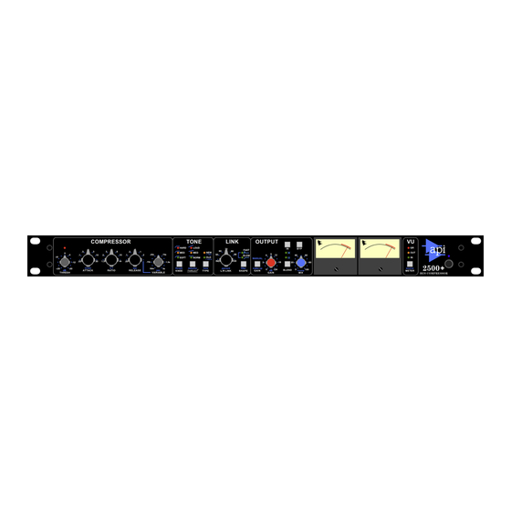
- Page 1 2500+ Stereo Bus Compressor OPERATOR’S MANUAL Written for Automated Processes Incorporated by Dan Pfeifer Rev. 23-01-09...
- Page 2 ©2019 8301 Patuxent Range Road Jessup, MD 20794 USA 301-776-7879 http://www.apiaudio.com...
-
Page 3: Table Of Contents
10.1 Power Switch ..................24 10.2 Rear Panel ....................24 10.2.1 Audio Connections ....................24 10.2.2 AC Power ......................25 APPENDIX....................26 A1 Specifications and Block Diagram............... 27 A2 Recall Chart ....................28 A3 API Limited Warranty and Service.............. 29... -
Page 4: About This Manual
About This Manual This manual explains the operation and applications of the API 2500+ Stereo Bus Compressor. This manual is organized in sections that correspond to the front panel controls and rear panel interface. Legend: • UPPER-CASE BOLD = POTS, SWITCHES, BUTTONS •... -
Page 5: Important Safety Instructions
Important Safety Instructions Please read these instructions Keep this information in a safe place Do not use this device near water Clean only with a dry cloth Do not block any ventilation openings Do not install near any heat sources such as radiators, heat registers, stoves, or other devices that produce heat Do not defeat the safety purpose of the polarized or grounding type AC plug Protect the AC power cord from being walked on or pinched... -
Page 6: Introduction
The L/R LINK feature is also unique to the API 2500+. First, there is a variable link control, ranging from IND (independent) to 50% through 100% in six steps. Variable linking allows combining of the Left/Right control voltages over a range, minimizing the interaction between channels, while still linking them to retain the stereo image. -
Page 7: Quick Start
VCA's to minimize noise and distortion found in single VCA compressors. The input and output stages are ALL DISCRETE, using the API 2510 and the API 2520 op amps. A TYPE switch that lets you choose between classic and modern compression characteristics: OLD for vintage-style feedback compression and NEW for today's more common feed-forward compression. -
Page 8: Overview
3.0 Overview The 2500+ Bus Compressor provides a comprehensive suite of controls: • THRESH (Threshold): The level at which compression begins (+20dBu to -20dBu) • Threshold LED: Indicates when the input audio crosses the selected threshold level • RATIO: The amount of compression applied after threshold 1.5:1, 2:1, 3:1, 4:1, 6:1, 10:1, and ∞:1 •... -
Page 9: Compressor Section
4.0 Compressor Section The COMPRESSOR section of the 2500+ sets the basic compression parameters for both the Left and Right channels. 4.1 Compressor Section Controls 4.1.1 THRESHOLD Threshold LED: Illuminates when the input audio crosses the level set by the THRESHOLD control •... -
Page 10: Attack
4.1.2 ATTACK ATTACK: Sets the time it takes the compressor to react when the level exceeds the set THRESHOLD Fixed attack times: .03, .1, .3, 1, 3, 10, and 30 milliseconds (m/sec) • 4.1.3 RATIO RATIO: Sets the ratio of input vs. output levels for signals that fall above the set THRESHOLD •... -
Page 11: Tone Section
5.0 Tone Section The TONE section of the 2500+ controls the shape of the response curve at the onset of compression THRUST (KNEE), inserts the patented ® filter before the detector, and set the detector path routing (TYPE). These controls all influence the tonal characteristics the compression applies to the audio. 5.1 Tone Section Controls 5.1.1 KNEE The KNEE function determines the shape of the 2500+’s response curve when the... - Page 12 HARD: Sharp response curve • Immediate onset of compression (sudden transition to set ratio) • More aggressive and noticeable • The red LED illuminates when engaged MED (Medium): Slightly rounded response curve • Moderate onset of compression (firm, but less sudden transition to set ratio) •...
-
Page 13: Thrust
The patented ® circuit has been used for many years in the famed API 2500+ Stereo Compressor, ATI Paragon and Paragon II consoles, as well as the Pro6 Input Strip. This circuit places a filter in front of the RMS detector with a slope of 10dB per decade (-3dB/8va), which is the inverse of the pink noise energy curve. -
Page 14: Type
based upon those louder low frequencies, resulting in a control voltage that favors the low frequencies of the signal, causing pumping and a loss of punch. Sometimes, this is not desirable. By engaging the THRUST ® switch, this inverse filter is placed in front of the RMS detector, evening out the energy by lowering the energy in the low frequencies and increasing the energy in the high frequencies, so each octave has the same energy instead of each octave having half the energy as the one lower. - Page 15 In a feed-back compressor, the RMS detector gets its signal from the output of the gain reduction device (VCA). This is how older API 525, 1176 type, and 660 type compressors work. This yields a smoother, softer, more transparent sound.
-
Page 16: Link Section
6.0 Link Section The LINK section of the 2500+ controls the amount each channel will influence the gain reduction of the opposite channel. This allows “center-image shifting” caused by differing amounts of gain reduction on each channel to be reduced or eliminated. Most stereo compressors only allow 100% linking between channels. -
Page 17: Link Shape
6.1.2 Link Shape The speed of the control voltage link between the Left and Right channels is selected using the SHAPE switch. SHAPE: Cycle to select the speed of the Left/Right control voltage link • FAST: Peak acting: RMS control voltage influence attenuated Green LED •... -
Page 18: Output Section
7.0 Output Section The output section of the 2500+ controls make-up gain, input/output blending, and compressor IN/out and bypass functions. 7.1 Output Section Controls 7.1.1 Make-up Gain MANUAL make-up GAIN: Toggle to select manual or auto make-up gain • Disengages “auto” make-up gain •... -
Page 19: Blend And Mix
7.1.2 Blend and Mix The output section of the 2500+ allows 100% of the compressed signal to be sent to the output, to be crossfaded with the input signal, or to be “blended” in parallel with the input signal. BLEND: Cycles to select the output mixing function •... - Page 20 The BYP (Bypass) switch is a relay hard-wired bypass that routes the signal directly from the INPUT XLR to the OUTPUT XLR, without going through any electronics. If the power fails to the 2500+, the BYP automatically engages, preventing any loss of signal during the power fault. BYP (Bypass): Toggle to engaged the hard-wired bypass Illuminates in red when engaged •...
-
Page 21: Stereo Vu Meters
8.0 Stereo VU Meters The Left and Right stereo VU meters can indicate gain reduction and the signal level at the INPUT and OUTPUT connectors. 8.1 VU Meter Controls 8.1.1 Stereo VU Meters The Left and Right stereo VU meters indicate the amount of gain reduction being applied, as well as the signal level at the INPUT and OUTPUT connectors. -
Page 22: Vu Meter Source
8.1.2 VU Meter Source The METER switch selects gain reduction, output, or input levels to be displayed on the VU meters. It is a silent function and is isolated so the VU selection does not affect or load the signal in any way. METER source: Cycle to select VU meter source signal •... -
Page 23: Side Chain Input
9.0 Side Chain Input The 2500+ provides access to the side chain to allow external keying of the gain reduction via the SIDE CHAIN input jack on the rear panel. SIDE CHAIN: Balanced, line-level input • ¼” TRS connector • Tip=+, Ring=-, Sleeve=ground NOTE: Only active when TYPE is set to NEW. -
Page 24: Power Switch & Rear Panel Connections
10.0 Power Switch & Rear Panel Connections 10.1 Power Switch The power switch for the 2500+ is located on the right side of the front panel. Power: Toggle to power the 2500+ ON and off • Blue LED illuminates when powered ON 10.2 Rear Panel The rear panel of the 2500+ provides the Left and Right audio input, output, and side chain connections, as well as AC power connections, voltage selection, and fuse. -
Page 25: Ac Power
10.2.2 AC Power The AC power connection, fuse, and voltage selection switch is located on the rear panel of the 2500+. 115/230V~: Voltage selection switch Fuse: 0.5A/0.25A 250V AC Power Connection: Standard IEC power cable 2500+ Bus Compressor... -
Page 26: Appendix
APPENDIX A1 Specifications and Block Diagram A2 Recall Chart A3 API Limited Warranty and Service 2500+ Bus Compressor... -
Page 27: A1 Specifications And Block Diagram
A1 Specifications and Block Diagram 2500+ Bus Compressor... -
Page 28: A2 Recall Chart
A2 Recall Chart 2500+ Bus Compressor... -
Page 29: A3 Api Limited Warranty And Service
API. Accordingly service or modification of any API unit except by an authorized API representative may VOID this warranty. API reserves the right to inspect any products that may be the subject of any warranty claims before repair or replacement is carried out. Final determination of warranty coverage lies solely with API. - Page 30 Dan Pfeifer is a Professor of Recording Industry at Middle Tennessee State University 2500+ Bus Compressor...
- Page 31 8301 Patuxent Range Road Jessup, MD 20794 USA 301-776-7879 http://www.apiaudio.com...
Need help?
Do you have a question about the 2500+ and is the answer not in the manual?
Questions and answers