Table of Contents
Advertisement
Quick Links
Download this manual
See also:
Manual
Advertisement
Table of Contents

Related Manuals for API 2500


Summary of Contents for API 2500
- Page 1 2500 Stereo Bus Compressor Anniversary Edition OPERATOR’S MANUAL Written for Automated Processes Incorporated by Dan Pfeifer Rev. 19-07-18...
- Page 2 ©2019 8301 Patuxent Range Road Jessup, MD 20794 USA 301-776-7879 http://www.apiaudio.com...
-
Page 3: Table Of Contents
Table of Contents About This Manual ..................4 Important Safety Instructions ..............5 1.0 Introduction ..................6 1.1 Features ..................... 6 2.0 Quick Start .................... 7 3.0 Overview ....................8 4.0 Compressor Section ................10 4.1 Compressor Section Controls ..............11 4.1.1 THRESHOLD ...................... -
Page 4: About This Manual
A3 API Limited Warranty and Service.............. 31 About This Manual This manual explains the operation and applications of the 50 Anniversary Edition of the API 2500 Stereo Bus Compressor. This manual is organized in sections that correspond to the front panel controls and rear panel interface. -
Page 5: Important Safety Instructions
Important Safety Instructions Please read these instructions Keep this information in a safe place Do not use this device near water Clean only with a dry cloth Do not block any ventilation openings Do not install near any heat sources such as radiators, heat registers, stoves, or other devices that produce heat Do not defeat the safety purpose of the polarized or grounding type AC plug Protect the AC power cord from being walked on or pinched... -
Page 6: Introduction
10-segment stereo gain reduction meter • Full hard-wired relay bypass • Commemorative serial number plate The 50th Anniversary 2500 has several unique features that will allow you to tailor the sound of the compression in many different directions. THRUST The patented ®... -
Page 7: Quick Start
The L/R LINK feature is also unique to the API 2500. First, there is a variable link control, ranging from IND (independent) to 50% through 100% in six steps. Variable linking allows combining of the Left/Right control voltages over a range, minimizing the interaction between channels, while still linking them to retain the stereo image. -
Page 8: Overview
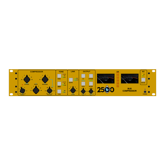
3.0 Overview The 50th Anniversary Edition of the API 2500 Stereo Bus Compressor provides a comprehensive suite of controls: • THRESH (Threshold): The level at which compression begins (+20dBu to -20dBu) • Threshold LED: Indicates when the input audio crosses the selected threshold level •... - Page 9 VU (stereo VU meters): Stereo Left and Right analog VU meters METER: Selects output or input as the source for the stereo VU meters • GR (gain reduction meters): Stereo Left and Right 10-segment gain reduction meters Anniversary 2500 Bus Compressor...
-
Page 10: Compressor Section
4.0 Compressor Section The COMPRESSOR section of the 50th Anniversary 2500 sets the basic compression parameters for both the Left and Right channels. Anniversary 2500 Bus Compressor... -
Page 11: Compressor Section Controls
RATIO: Sets the ratio of input vs. output levels for signals that fall above the set THRESHOLD • Fixed ratios: 1.5:1, 2:1, 3:1, 4:1, 6:1, 10:1, and ∞:1 (x:1) • Compression with ratios of 10:1 or greater is generally considered to be limiting Anniversary 2500 Bus Compressor... -
Page 12: Release
THRESHOLD • Fixed release times: .05, .1, .2, .5, 1, and 2 seconds (sec) • Variable release times continuously variable between 50m/sec and 3 seconds (sec) Anniversary 2500 Bus Compressor... -
Page 13: Tone Section
5.0 Tone Section The TONE section of the 50 Anniversary 2500 controls the shape of the response curve at the onset THRUST of compression (KNEE), inserts the patented ® filter before the detector, and set the detector path routing (TYPE). These controls all influence the tonal characteristics the compression applies to the audio. - Page 14 The red LED illuminates when engaged MED (Medium): Slightly rounded response curve • Moderate onset of compression (firm, but less sudden transition to set ratio) • Less aggressive and but still noticeable • The yellow LED illuminates when engaged Anniversary 2500 Bus Compressor...
-
Page 15: Thrust
The patented ® circuit has been used for many years in the famed API 2500 Stereo Compressor, ATI Paragon and Paragon II consoles, as well as the Pro6 Input Strip. This circuit places a filter in front of the RMS detector with a slope of 10dB per decade (-3dB/8va), which is the inverse of the pink noise energy curve. -
Page 16: Type
The green LED illuminates when engaged 5.1.3 TYPE The 50 Anniversary 2500 can be set to operate in two circuit topologies that determine where the signal that feeds the RMS detector comes from: • OLD: Feed-Back topology: The RMS detector receives the signal from after the VCA •... - Page 17 In a feed-back compressor, the RMS detector gets its signal from the output of the gain reduction device (VCA). This is how older API 525, 1176 type, and 660 type compressors work. This yields a smoother, softer, more transparent sound.
-
Page 18: Link Section
In addition, the 50 Anniversary 2500 allows the response speed of the Left/Right control voltage link to be filtered so the link acts on peak information (FAST) or RMS information (SLOW). If both are selected, both peak and RMS information is attenuated in the control voltage link, resulting in very subtle linkage. -
Page 19: Link Section Controls
• FAST: Peak acting: RMS control voltage influence attenuated Green LED • SLOW: RMS acting: peak control voltage influence attenuated Green LED • BOTH: Both peak and RMS link control voltage influence attenuated Both green LEDs Anniversary 2500 Bus Compressor... -
Page 20: Output Section
7.0 Output Section The output section of the 50 Anniversary 2500 controls make-up gain, input/output blending, and compressor IN/out and bypass functions. 7.1 Output Section Controls 7.1.1 Make-up Gain MANUAL make-up GAIN: Toggle to select manual or auto make-up gain •... -
Page 21: Blend And Mix
7.1.3 IN/out and Bypass The 50 Anniversary 2500 is equipped with a silent IN/out switch as well as a relay-based, hard-wired bypass. The IN switch is a soft IN/out button that defeats the compression action silently, but allows the signal to pass through the 50 Anniversary 2500. - Page 22 The BYPASS switch is a relay hard-wired bypass that routes the signal directly from the INPUT XLR to the OUTPUT XLR, without going through any electronics. If the power fails to the 50 Anniversary 2500, the BYPASS automatically engages, preventing any loss of signal during the power fault. BYPASS: Toggle to engaged the hard-wired bypass •...
-
Page 23: Meters
8.0 Meters The 50 Anniversary 2500 is equipped with premium quality Left and Right stereo VU meters and stereo LED gain reduction meters. The gain reduction meters (GR) indicate the amount of gain reduction being applied. The VU meters indicate the signal level at the INPUT and OUTPUT connectors. -
Page 24: Vu Meter Controls
It is a silent function and is isolated so the VU selection does not affect or load the signal in any way. METER: Toggle to select VU meter source signal • OUT (output): Meters indicate output levels Yellow LED • IN (input): Meters indicate input levels Green LED Anniversary 2500 Bus Compressor... -
Page 25: Side Chain Input
9.0 Side Chain Input The 50 Anniversary 2500 provides access to the side chain to allow external keying of the gain reduction via the SIDE CHAIN input jack on the rear panel. SIDE CHAIN: Balanced, line-level input • ¼” TRS connector •... -
Page 26: Power Switch & Rear Panel Connections
Blue LED illuminates when powered ON 10.2 Rear Panel The rear panel of the 2500 provides the Left and Right audio input, output, and side chain connections, as well as AC power connections, voltage selection, and fuse. 10.2.1 Audio Connections Each audio channel, Left and Right, has an INPUT, OUTPUT, and SIDE CHAIN input connection. -
Page 27: Ac Power
10.2.2 AC Power The AC power connection, fuse, and voltage selection switch is located on the rear panel of the 2500. 115/230V~: Voltage selection switch Fuse: 0.5A/0.25A 250V AC Power Connection: Standard IEC power cable 10.2.3 Commemorative Serial Number Plate... -
Page 28: Appendix
APPENDIX A1 Specifications and Block Diagram A2 Recall Chart A3 API Limited Warranty and Service Anniversary 2500 Bus Compressor... -
Page 29: A1 Specifications And Block Diagram
L / R L I N K R E L E A S E , M E T E R O L D R A T I O , K N E E REV A, 07-01-2019 Anniversary 2500 Bus Compressor... -
Page 30: A2 Recall Chart
R E L E A S E G A I N M I X N O T E S : REV A, 06-24-2019 R E V A , 0 6 - 2 4 - 2 0 1 9 Anniversary 2500 Bus Compressor... - Page 31 API. Accordingly service or modification of any API unit except by an authorized API representative may VOID this warranty. API reserves the right to inspect any products that may be the subject of any warranty claims before repair or replacement is carried out. Final determination of warranty coverage lies solely with API.
- Page 32 Dan Pfeifer is a Professor of Recording Industry at Middle Tennessee State University...
- Page 33 8301 Patuxent Range Road Jessup, MD 20794 USA 301-776-7879 http://www.apiaudio.com...
Need help?
Do you have a question about the 2500 and is the answer not in the manual?
Questions and answers