Advertisement
- 1 Introduction
- 2 Quick Start
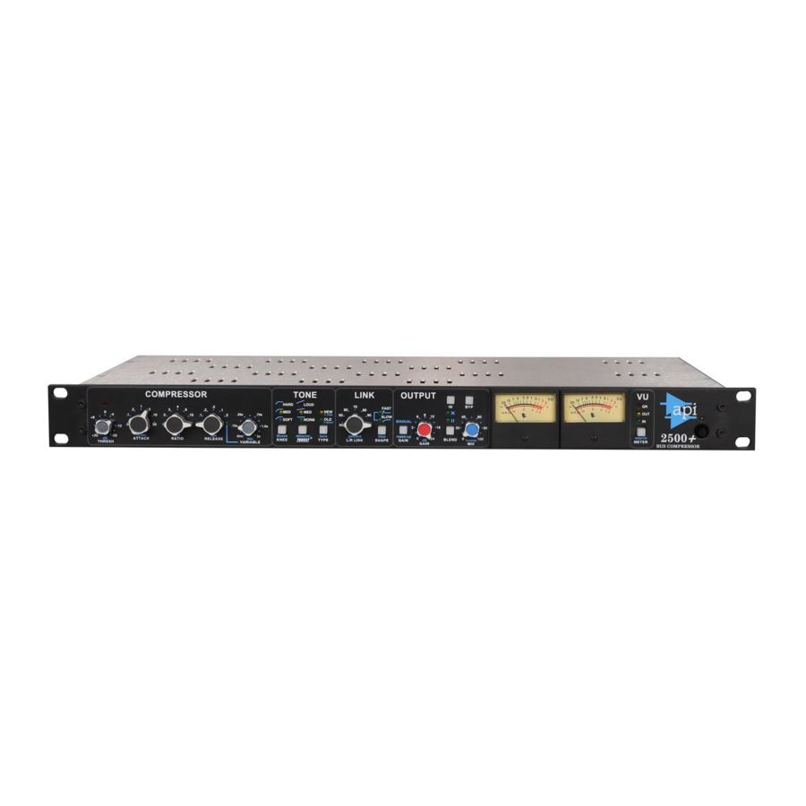
- 3 Overview
- 4 Compressor Section
- 5 Tone Section
- 6 Link Section
- 7 Output Section
- 8 Stereo VU Meters
- 9 Side Chain Input
- 10 Power Switch & Rear Panel Connections
- 11 Specifications and Block Diagram
- 12 Recall Chart
- 13 Warranty and Service
- 14 Important Safety Instructions
- 15 Documents / Resources
Introduction
The 2500+ Bus Compressor is API's flagship compressor that provides the unmistakable sound of API's compression technology combined with unmatched parametric control. The result is one of the world's best sounding and versatile stereo bus compressors that's capable of handling an infinite number of production applications. Carefully designed to deliver a wide range of compression options, the 2500+ delivers warmth, clarity and punch, whether used for subtle adjustments or heavy compression effects.

Features
- "Over Threshold" LED illuminates when input audio crosses the set threshold
- Patented THRUST® filter with 3 settings for frequency dependent side chain control
- 3 selectable compressor curve KNEE settings
- Selectable NEW or OLD type switch for feed-forward or feed-back operation
- Preset or variable release time control
- Variable Left/Right link with peak and RMS control voltage filters
- Selectable automatic or manually variable make-up gain
- Variable input-output blending for onboard crossfaded or parallel compression
- Audio circuit uses 2510 and 2520 discrete op amps with transformer output
- Stereo VU meters show selectable input, output, or gain reduction levels
- Full hard-wired relay bypass
The 2500+ has several unique features that will allow you to tailor the sound of the compression in many different directions.
The patented THRUST® feature has been used for many years in the famed ATI Paragon and Paragon II consoles, as well as the Pro-6 Input Strip. This circuit places a filter in front of the RMS detector, with a slope of 10dB per decade, which is the inverse of the pink noise energy curve. In acoustics, the pink noise curve is used to equalize energy vs. frequency over the audio spectrum, as sound requires more low frequency energy than high frequency energy to sound correct to your ear. In Hi-Fi equipment, a "LOUDNESS" contour is used to equalize the music at lower levels so it sounds correct. Even with this curve, there is still a substantial amount of low frequency information compared to high frequency information in the audio signal path. When that signal is fed into an RMS detector, the detector will process the signal into a DC control voltage based on those louder low frequencies, resulting in a control voltage that favors the low frequencies of the signal, causing pumping and a loss of punch. Sometimes, this is not desirable. By switching the THRUST® button in either the MED or LOUD positions, this inverse filter is placed in front of the RMS detector, evening out the energy by lowering the energy in the low frequencies and increasing the energy in the high frequencies, so each octave has the same energy instead of each octave having half the energy as the one lower. This creates a unique compression effect that still reduces the overall gain, but the sound is much more punchy and the signal actually sounds much less compressed.
The L/R LINK feature is also unique to the API 2500+. First, there is a variable link control, ranging from IND (independent) to 50% through 100% in six steps. Variable linking allows combining of the Left/Right control voltages over a range, minimizing the interaction between channels, while still linking them to retain the stereo image. While engaged, the link control has selectable detection speeds, FAST (peak) and SLOW (RMS). The 2500+ has two complete, identical compressor circuits, from the input through the RMS detector, the VCA's and to the output section.
When many compressors are linked to the "STEREO LINK" mode, only one channel is controlling the compression. When the 2500+ is linked, the control voltages are summed together, but both channels are still detecting their own control voltages. This also eliminates changing of the tone of the compressor when linking is used. Many popular units actually change when linked! Additionally, each channel uses multiple VCA's to minimize noise and distortion found in single VCA compressors. The input and output stages are ALL DISCRETE, using the API 2510 and the API 2520 op amps.
A TYPE switch that lets you choose between classic and modern compression characteristics: OLD for vintage-style feedback compression and NEW for today's more common feed-forward compression.
The 3-position KNEE switch adjusts the shape of the curve at the onset of compression for an "overeasy" type compression resulting in a very natural, uncompressed sound or a typical sharp knee type that lends itself to a much more severe limiting effect.
The auto make-up GAIN function lets you adjust ratio and threshold controls without affecting the output level. Alternately, make-up GAIN can be set manually.
The BLEND feature allows the mixed or parallel compression to be achieved on-board by allowing the input and compressed signals to be "blended" in two different ways: input vs. output wet/dry percentage (crossfade) or input plus output percentage (parallel).
Quick Start
One tip to get started: We try to design all of our processing modules with the understanding that there is never enough time to read a manual and learn all of the features in the 10 seconds that is allowed during a setup. If you simply set all of the parameters as follows the 2500+ will have a useful, but conservative effect on the signal.
- Set all of the knobs in the COMPRESSOR section to the 12:00 position
- Set KNEE to MED
- Set THRUST® to NORM
- Set TYPE to NEW
- Set L/R LINK to 50%
- Set SHAPE to SLOW
- Turn off MANUAL make-up gain (auto make-up gain on)
- Set BLEND to off: X (Crossfade) or l l (Parallel) not engaged
These settings will provide a good starting place for additional tweaking to achieve the desired sound.
Overview

The 2500+ Bus Compressor provides a comprehensive suite of controls:
- THRESH (Threshold): The level at which compression begins (+20dBu to -20dBu)
- Threshold LED: Indicates when the input audio crosses the selected threshold level
- RATIO: The amount of compression applied after threshold
- 1.5:1, 2:1, 3:1, 4:1, 6:1, 10:1, and ∞:1
- ATTACK: The time it takes for the compressor to respond
- .03, .1, .3, 1, 3, 10, and 30ms
- RELEASE: The time it takes the compressor to return to unity gain
- Fixed Times: .05, .1, .2, .5, 1, and 2 seconds
- Variable: 50ms to 3 seconds
- KNEE: Sets the characteristic of the response curve at the onset of compression
- HARD: Aggressive onset of compression
- MED (Medium): Moderate onset of compression
- SOFT: Smooth onset of compression
- THRUST®: Activates the patented circuit that inserts a filter before the RMS detector
- LOUD: Gradual, 10dB/decade filtero
- MED: Slight low-frequency attenuation and a slight high-frequency boost
- NORM (Normal): THRUST® filter not applied to side chain (flat)
- TYPE: Selects detection path routing
- NEW: feed-forward detection path
- OLD: feedback detection path
- L/R LINK: Sets the percentage of Left/Right control voltage link
- IND (Independent): Channels operate independently of each other or
- Percent: 50, 60, 70, 80, 90 or 100% linkage between channels
- SHAPE: Sets the speed of the Left/Right control voltage link
- FAST: Peak acting: RMS control voltage influence attenuated
- SLOW: RMS acting: peak control voltage influence attenuated
- Both: Both peak and RMS link control voltage influence attenuated
- MANUAL make-up GAIN: Selects MANUAL or automatic make-up gain
- GAIN: MANUAL make-up gain control (0dB to +24dB of output gain when MANUAL is engaged)
- BLEND: Selects output mixing mode: 100% compression, X=Crossfade, or l l=Parallel
- MIX: Sets the percentage of compressed signal and input signal sent to the outputs
- IN: Toggles to switch gain reduction IN or out
- BYP (Bypass): Toggles to engage the hard-wire bypass
- VU (stereo VU meters): Stereo Left and Right analog VU meters
- METER: Selects gain reduction (GR), output or input as the source for the stereo VU meters
Compressor Section
The COMPRESSOR section of the 2500+ sets the basic compression parameters for both the Left and Right channels.

Compressor Section Controls
THRESHOLD

Threshold LED: Illuminates when the input audio crosses the level set by the THRESHOLD control
- Red LED illuminates when input level crosses the set THRESHOLD
THRESHOLD: Sets the level at which compression begins Continuously variable range between +20dBu and -20dBu
ATTACK

ATTACK: Sets the time it takes the compressor to react when the level exceeds the set THRESHOLD
- Fixed attack times: .03, .1, .3, 1, 3, 10, and 30 milliseconds (m/sec)
RATIO

RATIO: Sets the ratio of input vs. output levels for signals that fall above the set THRESHOLD
- Fixed ratios: 1.5:1, 2:1, 3:1, 4:1, 6:1, 10:1, and ∞:1 (x: 1)
- Compression with ratios of 10:1 or greater is generally considered to be limiting
RELEASE

RELEASE: Sets the time it takes the compressor to recover to unity gain after the level falls below the set THRESHOLD
- Fixed release times: .05, .1, .2, .5, 1, and 2 seconds
- Variable release times continuously variable between 50m/sec and 3 seconds (sec)
Tone Section
The TONE section of the 2500+ controls the shape of the response curve at the onset of compression (KNEE), inserts the patented THRUST® filter before the detector, and set the detector path routing (TYPE). These controls all influence the tonal characteristics the compression applies to the audio.

Tone Section Controls
KNEE

The KNEE function determines the shape of the 2500+'s response curve when the input audio crosses the THRESHOLD.
The 2500+ has three (3) KNEE settings that control how the compressor transitions into compression:
- HARD: Sharp response curve
- Red LED
- MED (Medium): Slightly rounded response curve
- Yellow LED
- SOFT: Rounded response curve
- Green LED
HARD: Sharp response curve
- Immediate onset of compression (sudden transition to set ratio)
- More aggressive and noticeable
- The red LED illuminates when engaged


MED (Medium): Slightly rounded response curve
- Moderate onset of compression (firm, but less sudden transition to set ratio)
- Less aggressive and but still noticeable
- The yellow LED illuminates when engaged


SOFT: Rounded response curve
- Gradual onset of compression (fade-in up to the set ratio)
- Similar to an "over-easy" type knee
- More transparent
- The green LED illuminates when engaged


THRUST®
The 2500+ includes API's patented THRUST® circuit that can be switched in or out as needed. This places the THRUST® filter before the RMS detector that decreases the compressor's reaction to low frequency content. The result is a noticeable increase of punch and low frequencies, but a uniformly compressed signal. It's the "little more punch" switch!

The THRUST® circuit can be engaged using the THRUST® switch.
THRUST®: Cycle to select the THRUST® function
- LOUD: Inserts the LOUD THRUST® filter before the RMS detector
- Red LED
- MED (Medium): Inserts the MED THRUST® filter before the RMS detector
- Yellow LED
- NORM (Normal): No THRUST® filter before the RMS detector (flat)
- Green LED
The patented THRUST® circuit has been used for many years in the famed API 2500+ Stereo Compressor, ATI Paragon and Paragon II consoles, as well as the Pro6 Input Strip. This circuit places a filter in front of the RMS detector with a slope of 10dB per decade (-3dB/8va), which is the inverse of the pink noise energy curve. In acoustics, the pink noise curve is used to equalize energy vs. frequency over the audio spectrum, as sound requires more low frequency energy than high frequency energy to sound correct to your ear. In Hi-fi equipment, a "LOUDNESS" contour is used to equalize the music at lower levels so it sounds correct. Even with this curve, there is still a substantial amount of low frequency information compared to high frequency information in the audio signal path. When that signal is fed into the RMS detector, the detector will process the signal into a DC control voltage based upon those louder low frequencies, resulting in a control voltage that favors the low frequencies of the signal, causing pumping and a loss of punch. Sometimes, this is not desirable. By engaging the THRUST® switch, this inverse filter is placed in front of the RMS detector, evening out the energy by lowering the energy in the low frequencies and increasing the energy in the high frequencies, so each octave has the same energy instead of each octave having half the energy as the one lower. This creates a unique compression effect that still reduces the overall gain, but the sound is much more punchy and the signal actually sounds less compressed.
LOUD: A gradual, 10dB/decade filter is applied to the signal feeding the RMS detector, equalizing the energy going into the RMS detector. This decreases the way lower frequencies act on compression. The overall difference is a noticeable increase of punch and low frequencies, but a uniformly compressed signal. It is the "little more punch" function.
- The red LED illuminates when engaged
MED (Medium): A slight attenuation of the low frequencies and a slight boost in the high frequencies, with a flat mid-range are applied to the signal feeding the RMS detector. This reduces the low frequencies from pumping the compressor as much and increases the sensitivity of the RMS detector to the higher frequencies, affecting the higher frequency peaks of the signal.
- The yellow LED illuminates when engaged
NORM (Normal): The THRUST®filter is not inserted in the path to the RMS detector and the 2500+ compresses like most units on the market today (the signal in the detection path remains flat).
- The green LED illuminates when engaged
TYPE
The 2500+ can be set to operate in two circuit topologies that determine where the signal that feeds the RMS detector comes from:
- OLD: Feed-Back topology: The RMS detector receives the signal from after the VCA
- NEW: Feed-Forward topology: The RMS detector receives the signal from before the VCA

The detection path routing is selected using the TYPE switch.
TYPE: Toggle to select detection path routing
- NEW (F FWD): Engages the feed-forward topology
- Yellow LED
- OLD (F BACK): Engages feed-back topology
- Green LED
NEW (Feed-Forward)
In a feed-forward compressor, the RMS detector normally gets its signal from a split of the input signal. (The detector path can alternately get its signal from a SIDE CHAIN input jack.) With this method, the RMS detector sends a signal to the VCA that is an exact ratio of the desired compression set by the RATIO control. This is how many new VCA based compressors work. This can yield more aggressive compression and a harder, more affected sound.
- The yellow LED illuminates when engaged
")
")
OLD (Feed-back)
In a feed-back compressor, the RMS detector gets its signal from the output of the gain reduction device (VCA). This is how older API 525, 1176 type, and 660 type compressors work. This yields a smoother, softer, more transparent sound.
- The green LED illuminates when engaged
")
")
Link Section
The LINK section of the 2500+ controls the amount each channel will influence the gain reduction of the opposite channel. This allows "center-image shifting" caused by differing amounts of gain reduction on each channel to be reduced or eliminated.
Most stereo compressors only allow 100% linking between channels. The 2500+ allows for linking to start at IND (independent), where each channel operates as a separate compressor with 0% influence between channels. 50% to 100% in six additional steps can be applied the amount of linkage between channels. 100% will yield equal gain on both channels. At the same time, each channel is still controlled by its own detector, preventing loading and slaving from one side, which many times creates errors.
In addition, the 2500+ allows the response speed of the Left/Right control voltage link to be filtered so the link acts on peak information (FAST) or RMS information (SLOW). If both are selected, both peak and RMS information is attenuated in the control voltage link, resulting in very subtle linkage.
In combination, the 2500+ offers very accurate compression while providing the flexible and precise control needed to achieve exacting results in any application.

Link Section Controls
Left/Right Link

L/R LINK: Sets the percentage of the control voltage link between the Left and Right channels
- IND (independent): No linkage between channels; channels operate independently of each other with no influence from the opposite channel
- Percent: 50, 60, 70, 80, 90, and 100% fixed steps
Link Shape

The speed of the control voltage link between the Left and Right channels is selected using the SHAPE switch.
SHAPE: Cycle to select the speed of the Left/Right control voltage link
- FAST: Peak acting: RMS control voltage influence attenuated
- Green LED
- SLOW: RMS acting: peak control voltage influence attenuated
- Green LED
- BOTH: Both peak and RMS link control voltage influence attenuated
- Both green LEDs
Output Section
The output section of the 2500+ controls make-up gain, input/output blending, and compressor IN/out and bypass functions.

Output Section Controls
Make-up Gain

MANUAL make-up GAIN: Toggle to select manual or auto make-up gain
- Disengages "auto" make-up gain
- Engages the manual make-up GAIN pot
The "auto" make-up GAIN function applies make-up gain based upon the settings of the RATIO and THRESHOLD controls.

GAIN: Manual make-up gain (output level)
- Active only when the make-up function is set to MANUAL
- Continuously variable between 0dB and +24dB
Blend and Mix
The output section of the 2500+ allows 100% of the compressed signal to be sent to the output, to be crossfaded with the input signal, or to be "blended" in parallel with the input signal.

BLEND: Cycles to select the output mixing function
- 100% Compression: No output mixing
- No LEDs illuminated
- X (Crossfade): The MIX pot sets crossfade percentage between input and compressed signals (wet/dry function)
- Green LED illuminates when engaged
- l l (Parallel): The unattenuated input signal is routed to output at 100% and the MIX pot sets the percentage compressed signal added to the output
- Green LED illuminates when engaged
The MIX control functions only when either X or l l is engaged:
- X (Crossfade): Sets the percentage of input vs. compressed signal sent to the output:
- 0% sends only the unattenuated input signal to the output (dry)
- 50% (detent) sends 50% input signal and 50% compressed signal to the output
- 100% sends only the compressed signal to the output (wet)
- l l (Parallel): Sets the percentage of compressed signal added to the unattenuated input signal sent to the output:
- 0% sends only the unattenuated input signal to the output
- 50% (detent) sends unattenuated input signal, plus 50% of the compressed signal to the output
- 100% sends the unattenuated input signal, plus 100% of the compressed signal to the output

MIX: Sets the percentage of uncompressed and compressed signal (%comp) sent to the output when either X or l l is engaged
- Detent at 50%
IN/out and Bypass
The 2500+ is equipped with a silent IN/out switch as well as a relay-based, hard-wired bypass.
The IN switch is a soft IN/out button that defeats the compression action silently, but allows the signal to pass through the 2500+.

IN: Toggle to select compressor IN or out
- Illuminates in green when engaged
The BYP (Bypass) switch is a relay hard-wired bypass that routes the signal directly from the INPUT XLR to the OUTPUT XLR, without going through any electronics. If the power fails to the 2500+, the BYP automatically engages, preventing any loss of signal during the power fault.

BYP (Bypass): Toggle to engaged the hard-wired bypass
- Illuminates in red when engaged
 NOTE: When the 2500+ is powered off, it is held in the bypass state. When the compressor is not in the bypass state, the unit behaves normally.
Stereo VU Meters
The Left and Right stereo VU meters can indicate gain reduction and the signal level at the INPUT and OUTPUT connectors.

VU Meter Controls
Stereo VU Meters
The Left and Right stereo VU meters indicate the amount of gain reduction being applied, as well as the signal level at the INPUT and OUTPUT connectors. 0 VU is +4dBu.

The GAIN scale shows the amount of gain reduction during compression, with the 0 point being all the way to the right, allowing more resolution of the gain reduction scale. The range of the meter is from 0 (no gain reduction) to 20dB of gain reduction.
VU Meter Source
The METER switch selects gain reduction, output, or input levels to be displayed on the VU meters. It is a silent function and is isolated so the VU selection does not affect or load the signal in any way.

METER source: Cycle to select VU meter source signal
- GR (gain reduction): Meters indicate amount of gain reduction
- Red LED
- OUT (output): Meters indicate output levels
- Yellow LED
- IN (input): Meters indicate input levels
- Green LED
Side Chain Input
The 2500+ provides access to the side chain to allow external keying of the gain reduction via the SIDE CHAIN input jack on the rear panel.

SIDE CHAIN: Balanced, line-level input
- ¼" TRS connector
- Tip=+, Ring=-, Sleeve=ground
NOTE: Only active when TYPE is set to NEW.
When the TYPE control is set to NEW, the signal arriving at the INPUT connector is routed to the RMS detector via the SIDE CHAIN input jack. When a plug is not inserted in the SIDE CHAIN input jack, the input signal continues to the RMS detector. When a plug is inserted the SIDE CHAIN input jack, the input signal is replaced with the external signal.
"NEW" (FEED-FORWARD) COMPRESSION
 COMPRESSION")
Power Switch & Rear Panel Connections
Power Switch
The power switch for the 2500+ is located on the right side of the front panel.

Power: Toggle to power the 2500+ ON and off
- Blue LED illuminates when powered ON
Rear Panel
The rear panel of the 2500+ provides the Left and Right audio input, output, and side chain connections, as well as AC power connections, voltage selection, and fuse.

Audio Connections
Each audio channel, Left and Right, has an INPUT, OUTPUT, and SIDE CHAIN input connection.

INPUT: Balanced, line-level
- 3-pin female XLR connector
SIDE CHAIN: Balanced, line-level input
- ¼" TRS connector
- Tip=+, Ring=-, Sleeve=ground
OUTPUT: Balanced, line-level
- 3-pin male XLR connector
NOTE: Channel 1 = Left and Channel 2 = Right
AC Power
The AC power connection, fuse, and voltage selection switch is located on the rear panel of the 2500+.

115/230V~: Voltage selection switch
Fuse: 0.5A/0.25A 250V
AC Power Connection: Standard IEC power
Specifications and Block Diagram
2500+ SPECS / BLOCK DIAGRAM

| Rear Connectors: | XLR input, 1/4" side chain, XLR output |
| Maximum Output Level: | +32dB |
| Frequency Response: | ±0.5dB 20Hz to SOkHz |
| Signal to Noise Ratio: | 120dB |
| Power Consumption: | 28.8 Watts |
| Size: | 19" X 1.75" X 10.5" deep |
| Size (Boxed for Shipping): | 23.25" X 6.5" X 16" |
| Actual Weight: | 9.4 Ibs. |
| Shipping Weight: | 13.3 Ibs. |
BLOCK DIAGRAM

Recall Chart

Warranty and Service
For questions regarding operation, interfacing or service of your API product, please contact your API dealer from whom you purchased the unit. Many times your authorized API dealer is the fastest and most cost-effective way to maintain and service your product.
You may also contact API's Service Department directly:
Call API at 301-776-7879 (ext. 252) between 8:30 AM and 5:00 PM Monday through Friday (Eastern Time) to get a Return Authorization (RA). Products returned without an RA number may not be accepted.
Important Safety Instructions
- Please read these instructions
- Keep this information in a safe place
- Do not use this device near water
- Clean only with a dry cloth
- Do not block any ventilation openings
- Do not install near any heat sources such as radiators, heat registers, stoves, or other devices that produce heat
- Do not defeat the safety purpose of the polarized or grounding type AC plug
- Protect the AC power cord from being walked on or pinched
- Use only attachments/accessories specified by the manufacturer
- Unplug this device during lightning storms or when unused for long periods of time.
- Refer all service to qualified personnel
ATTENTION: Exposure to extremely high noise levels may cause permanent hearing loss or damage. Individuals vary considerably in susceptibility to noise-induced hearing loss, but nearly everyone will lose some hearing if exposed to sufficiently intense noise (this may include music) for a period of time. Be safe.

To reduce the risk of fire or electric shock, do not expose this apparatus to rain or moisture.
301-776-7879
Documents / Resources
References
Download manual
Here you can download full pdf version of manual, it may contain additional safety instructions, warranty information, FCC rules, etc.
Advertisement


Need help?
Do you have a question about the 2500+ and is the answer not in the manual?
Questions and answers