Table of Contents
Advertisement
Quick Links
Contents
Security ········································································································· 1
Safety information ·············································································································································· 1
General operating safety ···························································································································· 1
Electrical safety ·········································································································································· 1
Battery safety ············································································································································· 2
Safety precautions ············································································································································· 2
ESD prevention ·················································································································································· 2
Preventing electrostatic discharge ············································································································· 2
Grounding methods to prevent electrostatic discharge ·············································································· 3
Safety sign conventions ····································································································································· 3
About the server ···························································································· 5
Server models and chassis view ························································································································ 5
Server specifications ·········································································································································· 5
Product specifications ································································································································ 6
Technical specifications ····························································································································· 7
Components ······················································································································································· 8
Front panel ······················································································································································· 10
Front panel view ······································································································································· 10
LEDs and buttons ····································································································································· 12
Ports ························································································································································· 14
Rear panel························································································································································ 14
Rear panel view ······································································································································· 14
LEDs ························································································································································ 15
Ports ························································································································································· 16
System board ··················································································································································· 17
System board components ······················································································································ 17
System maintenance switch ····················································································································· 19
DIMM slots ··············································································································································· 20
HDDs and SSDs ·············································································································································· 20
Drive numbering ······································································································································· 20
Drive LEDs ··············································································································································· 22
Drive backplanes·············································································································································· 23
Front 8SFF SAS/SATA drive backplane ·································································································· 23
Front 8SFF UniBay drive backplane ········································································································ 23
Front 8LFF SAS/SATA drive backplane ··································································································· 24
Front 12LFF SAS/SATA drive backplane ································································································· 25
Front 8SAS/SATA+4UniBay drive backplane ·························································································· 25
Front 4SAS/SATA+8UniBay drive backplane ·························································································· 26
Front 12LFF UniBay drive backplane ······································································································· 26
Front 17SAS/SATA+8UniBay drive backplane ························································································ 27
Rear 2LFF SAS/SATA drive backplane ··································································································· 28
Rear 4LFF SAS/SATA drive backplane ··································································································· 29
Rear 2SFF SAS/SATA drive backplane ··································································································· 29
Rear 2SFF UniBay drive backplane ········································································································· 29
Rear 4SFF SAS/SATA drive backplane ··································································································· 30
Rear 4SFF UniBay drive backplane ········································································································· 30
Riser cards ······················································································································································· 31
RC-3FHFL-2U-G6 ···································································································································· 32
RC-3FHHL-2U-G6 ···································································································································· 33
RC-1FHHL-2U-G6 ···································································································································· 35
RC-2FHHL-2U-G6 ···································································································································· 35
Riser 4 assembly module (accommodating two FHFL PCIe modules) ···················································· 36
Riser 3 assembly module (accommodating two HHHL PCIe modules) ··················································· 36
Fan modules ···················································································································································· 37
LCD smart management module ····················································································································· 38
B/D/F information ············································································································································· 39
i
Advertisement
Table of Contents

Subscribe to Our Youtube Channel
Related Manuals for H3C UniServer R3950 G6


Summary of Contents for H3C UniServer R3950 G6
-
Page 1: Table Of Contents
Contents Security ········································································································· 1 Safety information ·············································································································································· 1 General operating safety ···························································································································· 1 Electrical safety ·········································································································································· 1 Battery safety ············································································································································· 2 Safety precautions ············································································································································· 2 ESD prevention ·················································································································································· 2 Preventing electrostatic discharge ············································································································· 2 Grounding methods to prevent electrostatic discharge ·············································································· 3 Safety sign conventions ·····································································································································... - Page 2 Component installation guidelines ··················································································································· 39 Processor ················································································································································· 39 DIMMs ······················································································································································ 39 SAS/SATA drives ····································································································································· 42 NVMe drives ············································································································································· 42 M.2 SSD drives ········································································································································ 42 Server management module ···················································································································· 43 Serial & DSD module ······························································································································· 44 Riser cards and PCIe modules ················································································································ 44 Storage controllers and power fail safeguard modules ············································································...
- Page 3 Prerequisites ············································································································································ 75 Procedures ··············································································································································· 75 Replacing a DIMM············································································································································ 77 Application scenarios ······························································································································· 77 Prerequisites ············································································································································ 77 Procedures ··············································································································································· 77 Installing a DIMM ····································································································································· 78 Verifying the replacement ························································································································ 78 Replacing the system board····························································································································· 78 Application scenarios ······························································································································· 78 Prerequisites ············································································································································ 78 Procedures ···············································································································································...
- Page 4 Replacing an OCP network adapter················································································································· 95 Application scenarios ······························································································································· 95 Prerequisites ············································································································································ 95 Procedures ··············································································································································· 95 Replacing a SATA M.2 SSD and the front M.2 SSD expander module ··························································· 96 Application scenarios ······························································································································· 96 Prerequisites ············································································································································ 96 Procedures ··············································································································································· 96 Replacing a serial &...
- Page 5 Connecting cables for OCP 3.0 network adapter 1 ························································································ 126 Connecting cables for riser cards··················································································································· 127 Connecting the supercapacitor cable ············································································································· 130 Connecting chassis ear cables ······················································································································ 130 Maintenance ······························································································ 131 Guidelines ······················································································································································ 131 Maintenance tools ·········································································································································· 131 Maintenance tasks ········································································································································· 131 Task list ··················································································································································...
-
Page 6: Security
General operating safety To avoid bodily injury or damage to the server, follow these guidelines when you operate the server: • Only H3C authorized or professional server engineers are allowed to install, service, repair, operate, or upgrade the server. •... -
Page 7: Battery Safety
Battery safety The server's system board contains a system battery, which is designed with a lifespan of 3 to 5 years. If the server no longer automatically displays the correct date and time, you might need to replace the battery. When you replace the battery, follow these safety guidelines: •... -
Page 8: Grounding Methods To Prevent Electrostatic Discharge
Table 1 Safety signs Sign Description Circuit or electricity hazards are present. Only H3C authorized or professional server engineers are allowed to service, repair, or upgrade the server. WARNING! To avoid bodily injury or damage to circuits, do not open any components marked with the electrical hazard sign unless you have authorization to do so. - Page 9 Sign Description The server is powered by multiple power supplies. WARNING! To avoid bodily injury from electrical shocks, make sure you disconnect all power supplies if you are performing offline servicing.
-
Page 10: About The Server
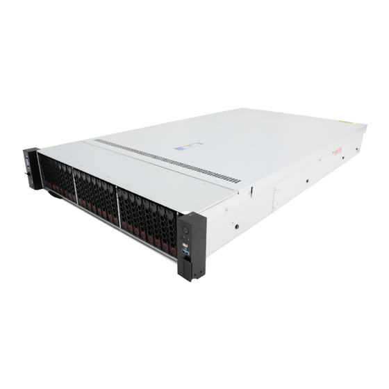
Figures in this document are for illustration only. Server models and chassis view H3C UniServer R3950 G6 server is a rack server based on AMD EPYC 9004 series processors developed by New H3C. The server is 2U high and supports one processor. It features low power consumption, high reliability, strong scalability, and easy management and deployment. -
Page 11: Product Specifications
Product specifications Item Specifications • 1 × AMD EPYC Genoa or Bergamo processors Up to 400 W power consumption per processor Up to 384 MB cache per processor Integrated memory controller, supports 12 memory channels Processors Integrated PCIe controller, supports PCIe5.0 and 128 PCIe Lanes per processor ... -
Page 12: Technical Specifications
34 kg (74.96 lb) Max. weight The power consumption varies by configuration. For more Power consumption information, visit H3C Server Power Consumption Evaluation. Operating temperature: 5°C to 45°C (41°F to 113°F) NOTE: The maximum operating temperature requirement for the server... -
Page 13: Components
Components Figure 2 R3950 G6 server components Item Description (1) Chassis access panel (2) Processor heatsink Cools the processor. (3) OCP network Network adapter installed onto the OCP network adapter connector on the adapter system board. Integrates memory and PCIe controllers to provide data processing capabilities (4) Processor for the server. - Page 14 Item Description backplane (13) Rear drive cage Installed at the server rear to accommodate drives. (14) Riser card blank Installed on an empty PCIe riser connector to ensure good ventilation. Supplies power to the server. The power supplies support hot swapping and 1+1 (15) Power supply redundancy.
-
Page 15: Front Panel
Front panel Front panel view Figure 3 8LFF front panel Table 3 8LFF front panel description Item Description USB 3.0 connector Drive or LCD smart management module (optional) Serial label pull tab HDM dedicated management connector USB 2.0 connector VGA connector Figure 4 12LFF front panel Table 4 12LFF front panel description Item... - Page 16 Item Description VGA connector Figure 5 8SFF front panel Table 5 8SFF front panel description Item Description Bay 1: 8SFF drives (optional)* Bay 2: 8SFF drives (optional)* Bay 3: 8SFF drives (optional)* USB 3.0 connector LCD smart management module (optional) Serial label pull tab HDM dedicated management connector USB 2.0 connector...
-
Page 17: Leds And Buttons
Item Description USB 3.0 connector Drive or LCD smart management module (optional) Serial label pull tab HDM dedicated management connector USB 2.0 connector VGA connector LEDs and buttons Front panel LEDs and buttons Figure 7 Front panel LEDs and buttons Table 7 LEDs and buttons on the front panel Button/LED Status... - Page 18 Button/LED Status • Flashing red (1 Hz)—A critical alarm is present. If a system alarm is present, log in to HDM to obtain more information about the system running status. • Steady blue—UID LED is activated. The UID LED can be activated by using the following methods: Press the UID button LED.
-
Page 19: Ports
Phase LED state supported) Major alarm present Flashing amber (1 Hz) Critical alarm present (only Flashing red (1 Hz) power error is supported) System is being remotely managed or HDM is updating All flashing white (1 Hz) Remote firmware through out-of-band control (Do not power off the server) HDM restarting... -
Page 20: Leds
Item Description PCIe riser bay 3: PCIe slots 7 and 8 Power supply 2 Power supply 1 OCP 3.0 network adapter/Serial & DSD module (optional) VGA connector Two USB 3.0 connectors HDM dedicated network port (1Gbps, RJ-45, default IP address 192.168.1.2/24) OCP 3.0 network adapter (optional) For more information about serial &... -
Page 21: Ports
Status does not output power. • Flashing green (2 Hz)—The power supply is updating its firmware. • Steady amber—Either of the following conditions exists: The power supply is faulty. The power supply does not have power input, but another power ... -
Page 22: System Board
System board System board components Figure 11 System board components Table 13 System board components Description Mark OCP 3.0 network adapter connector 2/DSD module connector OCP2&DSD&UART CARD Server management module connector BMC CON TPM/TCM connector System battery PCIe riser connector 1 RISER1 PCIe x16 Fan connector for OCP 3.0 network adapter 1 OCP1 FAN... - Page 23 Description Mark Front M.2 AUX connector M.2 AUX(FRONT) Drive backplane AUX connector 9 AUX 9 Power connector for OCP 3.0 network adapter 1 OCP1 PWR Front I/O connector RIGHT EAR Drive backplane AUX connector 3 AUX3 Drive backplane AUX connector 2 AUX2 LP SlimSAS connector C1-P4A C1-P4A...
-
Page 24: System Maintenance Switch
Description Mark MCIO connector C1-G3C C1-G3C Embedded USB3.0 connector INTER USB3.0 Liquid leakage detection module connector LEAKDET Drive backplane AUX connector 5 AUX5 Drive backplane AUX connector 6 AUX6 Drive backplane AUX connector 4 AUX4 System maintenance switch System maintenance switch Figure 12 shows the system maintenance switch. -
Page 25: Dimm Slots
Item Description Remarks CAUTION: The server cannot start up when the switch is turned on. To avoid service data loss, stop running services and power off the server before turning on the switch. • If this switch is on, the server will clear all the Off (default)—Normal server startup. - Page 26 Figure 14 Drive numbering for front 25SFF drive configuration Figure 15 Drive numbering for front 12LFF drive configuration Figure 16 Drive numbering for front 8LFF drive configuration Figure 17 Drive numbering for rear 2LFF+4SFF drive configuration Figure 18 Drive numbering for rear 4LFF+2SFF drive configuration Figure 19 Drive numbering for rear 2SFF+2SFF+4SFF drive configuration...
-
Page 27: Drive Leds
Drive LEDs The server supports SAS/SATA drives and NVMe drives. Figure 20 shows the location of the LEDs on a drive to indicate the drive status. Figure 20 Drive LEDs (1) Fault/UID LED (2) Present/Active LED To identify the status of a SAS or SATA drive, use Table 15. -
Page 28: Drive Backplanes
Drive backplanes The server supports the following types of drive backplanes: • SAS/SATA drive backplanes—Support only SAS/SATA drives. • UniBay drive backplanes—Support both SAS/SATA and NVMe drives. You must connect both SAS/SATA and NVMe data cables. The number of supported drives varies by drive cabling. -
Page 29: Front 8Lff Sas/Sata Drive Backplane
Figure 22 8SFF UniBay drive backplane (1) x8 SlimSAS connector (SAS PORT) (2) AUX ( AUX) (3) MCIO connector B3/B4 (PCIe5.0 x8)(NVMe B3/B4) (4) Power connector (POWER) (5) MCIO connector B1/B2 (PCIe5.0 x8)(NVMe B1/B2) (6) MCIO connector A3/A4 (PCIe5.0 x8)(NVMe A3/A4) (7) MCIO connector A1/A2 (PCIe5.0 x8)(NVMe A1/A2) PCIe5.0 x8 description: •... -
Page 30: Front 12Lff Sas/Sata Drive Backplane
Front 12LFF SAS/SATA drive backplane The PCA-BP-12LFF-2U-G6 12LFF SAS/SATA drive backplane can be installed at the server front to support twelve 3.5-inch SAS/SATA drives. Figure 24 12LFF SAS/SATA drive backplane (1) x4 SlimSAS connector (SAS PORT 2), managing the last four SAS/SATA drives on the backplane (2) Power connector 2 (PWR 2) (3) AUX connector (AUX) (4) Power connector 1 (PWR 1) -
Page 31: Front 4Sas/Sata+8Unibay Drive Backplane
(1) MCIO connector A3 (PCIe5.0 x4)(NVMe-A3), supporting NVMe drive 9 PCIe5.0 x8 description: • PCIe5.0: Fifth-generation signal speed. • x8: Bus bandwidth. Front 4SAS/SATA+8UniBay drive backplane The PCA-BP-12LFF-EXP-2U-G6 12LFF drive backplane can be installed at the server front to support twelve 3.5-inch SAS/SATA/NVMe drives, including four SAS/SATA drives and eight SAS/SATA/NVMe drives. -
Page 32: Front 17Sas/Sata+8Unibay Drive Backplane
Figure 27 12LFF UniBay drive backplane (1) MCIO connector A3 (PCIe5.0 x4)(NVMe-A3) (2) x4 SlimSAS connector (SAS PORT 2), managing the last four SAS/SATA drives on the backplane (3) MCIO connector B1/B2 (PCIe5.0 x8)(NVMe-B1/B2) (4) Power connector 2 (PWR 2) (5) AUX connector 1 (AUX 1) (6) MCIO connector C1 (PCIe5.0 x4)(NVMe-C1) (7) Power connector 1 (PWR 1) -
Page 33: Rear 2Lff Sas/Sata Drive Backplane
Figure 28 17SAS/SATA+8UniBay drive backplane (1) x4 SlimSAS downlink interface 3 (SAS EXP 3) (2) x8 SlimSAS uplink interface (SAS PORT), managing all drives on the backplane (3) x8 SlimSAS downlink interface 2 (SAS EXP 2) (4) x4 SlimSAS downlink interface 1 (SAS EXP 1) (5) Power connector 1 (PWR 1) (6) Power connector 2 (PWR 2) (7) MCIO connector 4 (PCIe5.0 x8)(NVMe 4), supporting NVMe drives 17 and 18... -
Page 34: Rear 4Lff Sas/Sata Drive Backplane
Rear 4LFF SAS/SATA drive backplane The PCA-BP-4LFF-2U-G6 4LFF SAS/SATA drive backplane is installed at the server rear to support four 3.5-inch SAS/SATA drives. Figure 30 4LFF SAS/SATA drive backplane (1) AUX connector (AUX1) (2) Power connector (PWR1) (3) x4 Mini-SAS-HD connector (SAS PORT1) Rear 2SFF SAS/SATA drive backplane The PCA-BP-2SFF-2U-G6 2SFF SAS/SATA drive backplane is installed at the server rear to support two 2.5-inch SAS/SATA drives. -
Page 35: Rear 4Sff Sas/Sata Drive Backplane
Figure 32 2SFF UniBay drive backplane (1) Power connector (PWR) (2) x4 Mini-SAS-HD connector (SAS PORT) (3) SlimSAS connector (PCIe4.0 x8)(NVME) (4) AUX connector (AUX) PCIe4.0 x8 description: • PCIe4.0: Fifth-generation signal speed. • x8: Bus bandwidth. Rear 4SFF SAS/SATA drive backplane The PCA-BP-4SFF-2U-G6 4SFF SAS/SATA drive backplane is installed at the server rear to support four 2.5-inch SAS/SATA drives. -
Page 36: Riser Cards
Figure 34 4SFF UniBay drive backplane (1) AUX connector (AUX) (2) Power connector (PWR) (3) MCIO connector B1/B2 (PCIe5.0 x8) (NVME-B1/B2) (4) MCIO connector B3/B4 (PCIe5.0 x8) (NVME-B3/B4) (5) x4 Mini-SAS-HD connector (SAS PORT) PCIe5.0 x8 description: • PCIe5.0: Fifth-generation signal speed. •... -
Page 37: Rc-3Fhfl-2U-G6
RC-3FHFL-2U-G6 Figure 35 RC-3FHFL-2U-G6 (1) Figure 36 RC-3FHFL-2U-G6 (2) (1) PCIe5.0 x16 (16,8,4,2,1) slot 2/5 (2) PCIe5.0 x16 (16,8,4,2,1) slot 3/6 (3) GPU module power connector (4) PCIe5.0 x16 (16,8,4,2,1) slot 1/4*... -
Page 38: Rc-3Fhhl-2U-G6
(1) PCIe5.0 x16 (16,8,4,2,1) slot 2/5 (2) PCIe5.0 x16 (16,8,4,2,1) slot 3/6 (5) MCIO connector 2-C (6) MCIO connector 2-A (7) MCIO connector 1-A (8) MCIO connector 1-C PCIe5.0 x16 (16,8,4,2,1) description: • PCIe5.0: Fifth-generation signal speed. • x16: Connector bandwidth. •... - Page 39 Figure 38 RC-3FHHL-2U-G6 (2) (1) PCIe5.0 x16 (8,4,2,1) slot 2/5 (2) PCIe5.0 x16 (8,4,2,1) slot 3/6 (3) PCIe5.0 x16 (16,8,4,2,1) slot 1/4* (4) MCIO connector 1-A (5) MCIO connector 1-C PCIe5.0 x16 (16,8,4,2,1) description: • PCIe5.0: Fifth-generation signal speed. • x16: Connector bandwidth.
-
Page 40: Rc-1Fhhl-2U-G6
RC-1FHHL-2U-G6 Figure 39 RC-1FHHL-2U-G6 (1) PCIe5.0 x16 slot 3/6* NOTE: slot 3/6: When the riser card is installed in PCIe riser bay 1, this slot corresponds to PCIe slot 3. When the riser card is installed in PCIe riser bay 2, this slot corresponds to PCIe slot 6. This rule applies to all the other PCIe slots. -
Page 41: Riser 4 Assembly Module (Accommodating Two Fhfl Pcie Modules)
Riser 4 assembly module (accommodating two FHFL PCIe modules) This riser 4 assembly module is as shown in Figure Figure 41 Riser 4 assembly module (accommodating two FHFL PCIe modules) PCIe interface cable S2 from slot 9 (connected to connector C1-P3C on the system board) PCIe interface cable S1 from slot 10 (connected to connector C1-G3A on the system board) PCIe5.0 x16 (16,8,4,2,1) in slot 10 PCIe5.0 x16 (16,8,4,2,1) in slot 9... -
Page 42: Fan Modules
Figure 42 Riser 3 assembly module (accommodating two HHHL PCIe modules) PCIe interface cable S1 from slot 8 (connected to connector C2-P3C on the system board) Power connector S2 from slot 8 (connected to connector PWR7 on the system board) PCIe5.0 x8 (8,4,2,1) in slot 8 PCIe5.0 x8 (8,4,2,1) in slot 7 Power connector S2 from slot 7 (connected to connector PWR6 on the system board) -
Page 43: Lcd Smart Management Module
Figure 43 Fan module layout LCD smart management module An LCD smart management module displays basic server information, operating status, and fault information, and provides diagnostics and troubleshooting capabilities. You can locate and troubleshoot component failures by using the LCD module in conjunction with the event logs generated in HDM. -
Page 44: B/D/F Information
• The server supports one processor. • To avoid damage to a processor or the system board, only H3C authorized or professional server engineers can install, replace, or remove a processor. • The pins in the processor sockets are very fragile and prone to damage. Install a protective cover if a processor socket is empty. - Page 45 Basic DIMM concepts DDR5 DIMMs can perform parity check on addresses and the DDR5 DIMMs cannot protect data from getting lost in case of unexpected system power outage. Rank The number of ranks is usually 1, 2, 4, or 8, generally abbreviated as 1R/SR, 2R, 4R, 8R, or single-rank, dual-rank, quad-rank, or 8-rank.
- Page 46 To obtain the memory frequency and maximum memory frequency supported by a specific processor, use the component compatibility lookup tool at http://www.h3c.com/en/home/qr/default.htm?id=66. You can query the memory frequency by selecting Memory Module and query the maximum supported memory frequency by selecting Processor.
-
Page 47: Sas/Sata Drives
Figure 46 DIMM population scheme for the processor DIMM configuration Number of DIMMs This information is for DDR5 modules only. For information about installing any other DIMMs, see the user guide for the device. DIMM slots 1DIMM √ ● 2DIMMs √... -
Page 48: Server Management Module
Figure 47 Front M.2 SSD expander module (front view) (1) Data cable connector (2) M.2 SSD drive slot 1 Figure 48 Front M.2 SSD expander module (rear view) (1) M.2 SSD drive slot 2 Server management module The server management module is installed on the system board to provide I/O connectors and HDM out-of-band features for the server. -
Page 49: Serial & Dsd Module
(1) VGA connector (2) Two USB 3.0 connectors (3) HDM dedicated network interface (4) UID LED (5) HDM serial port (6) iFIST module (7) NCSI connector Serial & DSD module The serial & DSD module is installed in the slot on the server rear panel. The module provides two SD slots and forms RAID 1 by default. - Page 50 • FHFL—Full height and full length. • HHHL—Half height and half length. • HHFL—Half height and full length. Restrictions and guidelines For information about PCI riser connectors on the system board, see "System board components." For information about PCIe slots on riser cards, see "Riser cards."...
- Page 51 Riser PCIe slots PCIe slot or PCIe module for PCIe slot Riser card card on a riser connector PCIe slot or power location model card description connector capability link for slot 2 with another x8 MCIO connector SLOT 2-A Slots 4 PCIe5.0 x16 FHFL 75 W...
- Page 52 Riser PCIe slots PCIe slot or PCIe module for PCIe slot Riser card card on a riser connector PCIe slot or power location model card description connector capability MCIO connector SLOT PCIe5.0 x16 Slot 4 FHHL 75 W (16,8,4,2,1) PCIe5.0 x16 Slot 5/6 FHHL 75 W...
-
Page 53: Storage Controllers And Power Fail Safeguard Modules
Make sure the standard storage controllers are of the same vendor (PMC or LSI). For information about the available storage controllers and their vendors, use the component compatibility lookup tool at http://www.h3c.com/en/home/qr/default.htm?id=66. • If the drives are installed only at the server front, install storage controllers to different riser cards. -
Page 54: Network Adapters
• If the drives are installed at both the server front and server rear, install storage controllers to one riser card. The controller in a lower-numbered slot is connected to the front drive backplane and the controller in a higher-numbered slot to the rear drive backplane. For information about slot locations, see the rear panel view in "Rear panel view."... -
Page 55: Power Supplies
The power supplies are hot swappable. To avoid damage to hardware, use only H3C approved power supplies. The server supports 1+1 power supply redundancy. The system provides an overtemperature mechanism for power supplies. The power supplies automatically turn off when they encounter an overtemperature situation and automatically turn on when the overtemperature situation is removed. - Page 56 The server must be fully configured with fan modules of the same model. The server supports both single-rotor FAN-8038-2U-G6 fan module and dual-rotor FAN-8056-2U-G6 fan module. When any of the following conditions are met, you must install the FAN-8056-2U-G6 fan module: •...
-
Page 57: Installing Or Removing The Server
Table 29 Installation requirements for different rack depths Rack depth Installation requirements • The H3C cable management arm (CMA) is not supported. • A clearance of 60 mm (2.36 in) is reserved from the server rear to the rear rack door for cabling. - Page 58 Figure 51 Installation recommendations for a 1200 mm deep rack (top view) (1) 1200 mm (47.24 in) rack depth (2) A minimum of 50 mm (1.97 in) between the front rack posts and the front rack door (3) 780 mm (30.71 in) between the front rack posts and the rear of the chassis, including power supply handles at the server rear (not shown in the figure) (4) 800 mm (31.50 in) server depth, including chassis ears (5) 960 mm (37.80 in) between the front rack posts and the CMA...
-
Page 59: Airflow Direction Of The Server
Airflow direction of the server Figure 52 Airflow direction of the server (1) and (2) Directions of the airflow into the chassis and power supplies (3) Directions of the airflow out of the power supplies (4) and (5) Direction of the airflow out of the chassis Temperature and humidity requirements To ensure correct operation of the server, make sure the room temperature and humidity meet the requirements as described in... - Page 60 Corrosive gas Sources acid manufacture, and tobacco smoke. Sulphur (S) Foundries and sulfur manufacture. Fertilizer manufacture, aluminum manufacture, ceramics Hydrogen Fluoride (HF) manufacture, steel manufacture, electronics device manufacture, and fossil fuel. Automobile emissions, fossil fuel combustion, microbes, and Nitrogen Oxide (NO chemical industry.
- Page 61 NOTE: • Part per billion (ppb) is a concentration unit. 1 ppb represents a volume-to-volume ratio of 1 to 100000000. • The concentration limits are calculated based on the reaction results of the gases in the equipment room with a relative humidity less than 50%. If the relative humidity of the equipment room increases by 10%, the severity level of ANSI/ISA 71.04-1985 to be meet must also increase by 1.
-
Page 62: Cleanliness Requirements
• Employ a professional company to monitor and control corrosive gases in the equipment room regularly. Cleanliness requirements Requirements of dust particle concentration vary by server model. For information about the requirements, see the installation guide of the server. Requirements for the data center equipment room The concentration of dust participles in the equipment room must meet the ISO 8 cleanroom standard defined by ISO 14644-1, as described in Table... -
Page 63: Installation Tools
• As a best practice, do not store an SSD, M.2 SSD, or SD card for 3 months or more without powering on and using it. Long unused time increases data loss risks. • To store the server chassis, or an HDD and SSD for 3 months or more, power on it every 3 months and run it for a minimum of 2 hours each time. - Page 64 Picture Name Description ESD wrist strap Prevents ESD when you operate the server. Antistatic gloves Prevents ESD when you operate the server. Antistatic clothing Prevents ESD when you operate the server. Ladder Supports high-place operations. Interface cable (such as an Ethernet cable or optical Connects the server to an external network.
-
Page 65: Installing The Server
Picture Name Description Temperature and humidity Displays current temperature and humidity. meter Displays the variation of voltage over time in Oscilloscope waveforms. Installing the server Installing rails Install the inner rails to the server and the outer rails to the rack. For information about installing the rails, see the document shipped with the rails. -
Page 66: Installing Cable Management Brackets
VGA driver. To obtain the new VGA driver, access the H3C official website, select Software Download > Servers, and enter "VGA" in the search box. The server provides two DB15 VGA connectors for connecting a monitor. One is on the front panel and the other is on the rear panel. - Page 67 Figure 55 Connecting a VGA cable Connect the other plug of the VGA cable to the VGA connector on the monitor, and fasten the screws on the plug. Connect the mouse and keyboard. For a USB mouse and keyboard, directly connect the USB connectors of the mouse and ...
-
Page 68: Connecting An Ethernet Cable
Connecting an Ethernet cable About this task Perform this task before you set up a network environment or log in to the HDM management interface through the HDM network port to manage the server. Procedure Determine the network port on the server. To connect the server to the external network, use the Ethernet port on the network adapter. -
Page 69: Connecting The Power Cord
Connecting the power cord Guidelines WARNING! To avoid damage to the equipment or even bodily injury, use the power cord that ships with the server. Before connecting the power cord, make sure the server and components are installed correctly. Procedure Insert the power cord plug into the power receptacle of a power supply at the rear panel, as shown in Figure... - Page 70 Figure 59 Sliding the cable clamp backward b. Open the cable clamp, place the power cord through the opening in the cable clamp, and then close the cable clamp, as shown by callouts 1, 2, 3, and 4 in Figure Figure 60 Securing the AC power cord c.
-
Page 71: Securing Cables
Figure 61 Sliding the cable clamp forward Securing cables Securing cables to cable management brackets For information about how to secure cables to cable management brackets, see the installation guide shipped with the brackets. Securing cables to slide rails by using cable straps You can secure cables to either left slide rails or right slide rails. -
Page 72: Cabling Guidelines
Figure 62 Securing cables to a slide rail Cabling guidelines WARNING! To avoid electric shock, fire, or damage to the equipment, do not connect communication equipment to RJ-45 Ethernet ports on the server. • For heat dissipation, make sure no cables block the inlet or outlet air vents of the server. •... - Page 73 Figure 63 Extending the server from the rack Place the server on a clean, stable surface.
-
Page 74: Powering On And Powering Off The Server
Powering on and powering off the server Important information If the server is connected to external storage devices, make sure the server is the first device to power off and then the last device to power on. This restriction prevents the server from mistakenly identifying the external storage devices as faulty devices. -
Page 75: Powering Off The Server
a. Select System > Power Management. b. In the System power restore area, select Always power on, and then click OK. To configure automatic power-on from the BIOS: Log in to the BIOS. For information about how to log in to the BIOS, see the BIOS user guide for the server. Configure automatic power-on for the server. - Page 76 Powering off the server from the remote console interface Log in to HDM. For information about how to log in to HDM, see the HDM2 user guide for the server. Log in to a remote console and then power off the server. For information about how to log in to a remote console, see HDM online help.
-
Page 77: Configuring The Server
Configuring the server The following information describes the procedures to configure the server after the server installation is complete. Configuration flowchart Figure 64 Configuration flowchart Start Power on the server (Optional) Configure BIOS Configure RAID Install operating system and drivers Update firmware Powering on the server Power on the server. -
Page 78: Configuring Basic Bios Settings
Installing the operating system Install a compatible operating system on the server by following the procedures described in the operating system installation guide for the server. For the server compatibility with the operating systems, visit the component compatibility lookup tool at http://www.h3c.com/en/home/qr/default.htm?id=66. -
Page 79: Installing Hardware Drivers
Installing hardware drivers IMPORTANT: To avoid hardware unavailability caused by an update failure, always back up the drivers before you update them. For newly installed hardware to operate correctly, the operating system must have the required hardware drivers. To install a hardware driver, see the operating system installation guide for the server. Updating firmware IMPORTANT: Verify the hardware and software compatibility before firmware upgrade. -
Page 80: Replacing Hardware Options
Procedures Restrictions and guidelines To avoid damage to a processor or the system board, only H3C authorized or professional server engineers can replace a processor. The pins in the processor sockets are very fragile and prone to damage. Install a protective cover if a processor socket is empty. - Page 81 1.6 N·m (16.1 kgf.cm). • Paste the bar code label supplied with the processor over the original label on the heatsink to ensure that you can obtain H3C's processor servicing. Install the chassis air baffle.
-
Page 82: Replacing A Dimm
b. Slide the access panel to the server front and close the locking lever. The access panel snaps into place. Rack-mount the server. For more information, see "Rack-mounting the server." Connect the power cord. For more information, see "Connecting the power cord."... -
Page 83: Installing A Dimm
Installing a DIMM Install the DIMM. Align the notch on the DIMM with the connector key in the DIMM slot and press the DIMM into the socket until the latches lock the DIMM in place. Install the chassis air baffle. Install the access panel: a. -
Page 84: Procedures
When you replace a component, examine the slot and connector for damages. Make sure the pins are not damaged (bent for example) and do not contain any foreign objects. Procedures Removing the system board CAUTION: To prevent electrostatic discharge, place the removed parts on an antistatic surface or in antistatic bags Power off the server. -
Page 85: Replacing The Server Management Module
Connect cables to the system board. Install heatsinks. Install DIMMs. Install the fan cage and fan modules. Install the chassis air baffle. Install the removed power supplies. 10. Install the serial & DSD module. 11. Install riser cards and connect cables to riser cards. 12. - Page 86 Remove the fan cage. Pull up the ejector levers at both sides of the fan cage and lift the fan cage to remove it from the chassis. 10. Remove DIMMs from the system board. 11. Remove heatsinks. 12. Remove the processors. 13.
-
Page 87: Replacing A Sas/Sata Drive
Replacing a SAS/SATA drive Application scenarios Perform this task in the following scenarios: • The drive is faulty. • The drive space is used up. • Replace the drive with one of another model. Prerequisites Take the following ESD prevention measures: •... -
Page 88: Verifying The Replacement
NOTE: Only some operating systems support the hot insertion of NVMe drives. For more information, use the component compatibility lookup tool at http://www.h3c.com/en/home/qr/default.htm?id=66. Remove the intelligent security bezel, if any. Install the drive into the drive carrier. Secure the four screws into the screw holes, and then fasten the screws in sequence. -
Page 89: Verifying The Replacement
• Support for hot swapping of NVMe drives depends on the operating system. For more information, use the component compatibility lookup tool at http://www.h3c.com/en/home/qr/default.htm?id=66. • To replace an NVMe drive in an operating system that does not support hot swapping, first power off the server. -
Page 90: Verifying The Replacement
Remove the drive carrier. Remove the screws that secure the drive and then remove the drive from the carrier. Installing an NVMe drive Install an NVMe drive. Attach the drive to the drive carrier. Place the drive in the carrier and then use four screws to secure the drive into place. -
Page 91: Installing A Rear Drive Cage
Remove the fan modules. Remove the fan cage. Pressing the locking tabs at both ends of the fan cage, lift the fan cage to remove it out of the chassis. Disconnect cables from the backplane. Remove the drive backplane. Loosen the captive screws that secure the backplane, and then lift the backplane out of the chassis. -
Page 92: Replacing Riser Cards And Pcie Modules
a. Place the drive cage in the chassis. b. Use screws to secure the drive cage. Connect the cables. See "Connecting drive cables." Install the blank. Aligning the guide pins on the blank with the notches in the chassis, insert the blank into the slot. -
Page 93: Installing Pcie Modules And A Riser Card On Pcie Riser Bay 3
a. Remove the screws on the riser card. b. Pull the PCIe module out of the slot. Installing a riser card and a PCIe module Install the PCIe module on the riser card: a. Remove the PCIe module blank. Remove the screws on the blank, and then pull out the blank. -
Page 94: Installing Pcie Modules And A Riser Card On Pcie Riser Bay 4
Lift the PCIe riser card blank to remove it. Assemble the riser 3 assembly module in advance as required. Install a PCIe module to the riser 3 assembly module: a. Remove the PCIe module blank. Loosen the screws on the PCIe module blank, and then remove the PCIe module blank. -
Page 95: Replacing A Storage Controller And A Power Fail Safeguard Module
Assemble the riser 4 assembly module in advance as required. Install a PCIe module to the riser 4 assembly module: a. Remove the PCIe module blank. Loosen the screws on the PCIe module blank, and then remove the PCIe module blank. b. -
Page 96: Procedures
• BIOS boot mode. • First boot option setting for the storage controller in Legacy boot mode. To replace the storage controller with a controller of a different model, back up data in the drives of the storage controller and clear RAID configuration. For information about installation guidelines, see "Storage controllers and power fail safeguard modules."... -
Page 97: Replacing A Gpu Module
Replacing a GPU module Application scenarios Perform this task in the following scenarios: • The GPU module is faulty. • Replace the GPU module with one of another model. • The GPU module hinders maintenance of other components. Prerequisites Take the following ESD prevention measures: •... -
Page 98: Replacing A Standard Pcie Network Adapter
Installing a GPU module Install a GPU module on the riser card: a. Insert the GPU module into the PCIe slot along the guide rails, and then close the retaining latch on the riser card. b. (Optional.) Connect the GPU module power cord according to the cable label. Reconnect other cables to the riser card. -
Page 99: Adding An Ocp Network Adapter
Remove the riser card that holds the PCIe network adapter. Lift the riser card to remove it from the chassis. Remove the PCIe network adapter from the riser card. Loosen the captive screws on the riser card and pull the PCIe network adapter out of the slot. Installing a standard PCIe network adapter For more information, see "Installing a riser card and a PCIe... -
Page 100: Replacing An Ocp Network Adapter
Replacing an OCP network adapter Application scenarios Perform this task in the following scenarios: • The OCP network adapter is faulty. • Replace the OCP network adapter with one of another model. Prerequisites Take the following ESD prevention measures: • Wear antistatic clothing. -
Page 101: Replacing A Sata M.2 Ssd And The Front M.2 Ssd Expander Module
Replacing a SATA M.2 SSD and the front M.2 SSD expander module Application scenarios Perform this task in the following scenarios: • The SATA M.2 SSD drive is faulty. • The M.2 SSD expander module is faulty. • Replace the SATA M.2 SSD drive with one of another model. Prerequisites Take the following ESD prevention measures: •... -
Page 102: Replacing A Serial & Dsd Module
b. Connect the SATA M.2 SSD cable. For more information, see "Connecting cables for the front M.2 SSD expander module." Install the access panel: a. Place the access panel onto the server. b. Slide the access panel to the server front and close the locking lever. The access panel snaps into place. -
Page 103: Procedures
• Wear antistatic clothing. • Wear an ESD wrist strap and make sure it makes good skin contact and is reliably grounded. • Do not wear any conductive objects, such as jewelry or watches. When you replace a component, examine the slot and connector for damages. Make sure the pins are not damaged (bent for example) and do not contain any foreign objects. -
Page 104: Replacing A Chassis Air Baffle
Remove the chassis air baffle. Lift the air baffle out of the chassis. Remove the front I/O component cable assembly: a. Disconnect the front I/O component cable assembly from the system board. b. Remove the cable protection plate. Remove the captive screws that secure the cable protection plate, press the cable protection plate and slide it toward the rear of the chassis until you cannot slide it further, and then pull out the cable protection plate. -
Page 105: Adding An Lcd Smart Management Module
Remove the chassis air baffle. Press the tabs on the air baffle, and then lift the air baffle out of the chassis. Installing a chassis air baffle Install the chassis air baffle. Place the chassis air baffle in the chassis. Install the access panel: a. -
Page 106: Replacing An Lcd Smart Management Module
10. Connect the power cord. For more information, see "Connecting the power cord." 11. Power on the server. For more information, see "Powering on the server." Replacing an LCD smart management module Applications scenarios Perform this task in the following scenarios: •... -
Page 107: Replacing A Fan Module
b. Slide the access panel to the server front and close the locking lever. The access panel snaps into place. Rack-mount the server. For more information, see "Rack-mounting the server." Connect the power cord. Power on the server. For more information, see "Powering on the server."... -
Page 108: Installation And Setup Flowchart
system security and data protection. For information about Microsoft Windows BitLocker, visit the Microsoft website at http://www.microsoft.com. Trusted cryptography module (TCM) is a trusted computing platform-based hardware module with protected storage space, which enables the platform to implement password calculation. Installation and setup flowchart Figure 65 TCM/TPM installation and setup flowchart Start... -
Page 109: Enabling The Tcm Or Tpm In The Bios
• H3C is not liable for blocked data access caused by improper use of the TCM or TPM. For more information, see the encryption technology feature documentation provided by the operating system. -
Page 110: Replacing A Power Supply
The recovery key/password is generated during BitLocker setup, and can be saved and printed after BitLocker is enabled. When using BitLocker, always retain the recovery key/password. The recovery key/password is required to enter Recovery Mode after BitLocker detects a possible compromise of system integrity or firmware or hardware change. -
Page 111: Replacing The System Battery
b. Press the tab on the CMA connector next to the power supply and then pull the connector out. Remove the power supply. Holding the power supply by its handle and pressing the retaining latch with your thumb, pull the power supply slowly out of the slot. Installing a power supply If only one power supply is present, install the new power supply in the slot for the replaced power supply. -
Page 112: Removing And Installing A Blank
The access panel automatically slides to the server rear. b. Lift the access panel to remove it from the server. Remove the system battery. Pinch the system battery by its top edge and the battery will disengage from the battery holder. NOTE: For environment protection purposes, dispose of the used-up system battery at a designated site. - Page 113 Table 35 Removing or installing a blank Task Procedure Press the latches on the drive blank inward with one hand, and pull Remove a drive blank. the drive blank out of the slot. Install a drive blank. Insert the drive blank into the slot. From the inside of the chassis, use a flat-head screwdriver to push Remove a drive backplane blank.
-
Page 114: Connecting Internal Cables
Connecting internal cables Internal cabling guidelines Application scenarios Internal server cabling diagram can be used in the following scenarios: • To guide cable connections after expanding or replacing components. • To guide cable reseating if cables are loose or disconnected. •... -
Page 115: 12Lff (8 Sas/Sata + 4 Unibay) Drives At The Front
12LFF (8 SAS/SATA + 4 UniBay) drives at the front Connect NVMe data cables for the 12LFF drives at the front. Figure 66 Connecting NVMe data cables for the 12LFF drives at the front Cable type Cable code Description From connectors NVME A3 and NVME A4 on the NVMe data cable 0404A2BG front backplane to connector C1-P3C on the storage... - Page 116 Figure 67 Connecting a SAS/SATA cable for the 12LFF drives at the front Cable type Cable code Description SAS/SATA data From connector SAS PORT1 on the front drive 0404A2B7 cable backplane to connector C1-P0C on the system board Connect an AUX cable for the 12LFF drives at the front. Figure 68 Connecting an AUX cable for the 12LFF drives at the front Cable type Description...
-
Page 117: 12Lff Drives At The Front + 2Sff Unibay Drives At The Rear
Connect power cords for the 12LFF drives at the front. Figure 69 Connecting power cords for the 12LFF drives at the front Cable type Description From connector PWR1 on the front drive backplane to connector PWR1 Power cord on the system board From connector PWR2 on the front drive backplane to connector PWR2 Power cord on the system board... - Page 118 Figure 70 Connecting an SAS/SATA data cable for the 12LFF drives at the front Cable type Cable code Description From connector SAS PORT1 on the front SAS/SATA data cable 0404A2B7 backplane to connector C1-P0C on the storage controller. From connector SAS PORT2 on the front SAS/SATA data cable 0404A2AW backplane to connector C1-G3A on the storage...
- Page 119 Cable type Cable code Description From connector AUX1 on the front drive backplane to connector AUX1 AUX cable on the system board Connect power cords for the 12LFF drives at the front. Figure 72 Connecting power cords for the 12LFF drives at the front Cable type Description From connector PWR1 on the front drive backplane to connector PWR1...
- Page 120 Figure 73 Connecting an NVME data cable for the 2SFF UniBay drives at the rear Cable type Cable code Description From connector NVME on the front drive backplane NVMe data cable 0404A2AL to connector C1-P3C on the system board Connect an AUX data cable for the 2SFF UniBay drives at the rear. Figure 74 Connecting an AUX data cable for the 2SFF UniBay drives at the rear Cable type Description...
-
Page 121: 12Lff (4 Sas/Sata + 8 Unibay, Lsi Expander) Drives At The Front
Connect a power cord for the 2SFF UniBay drives at the rear. Figure 75 Connecting a power cord for the 2SFF UniBay drives at the rear Cable type Description From connector PWR on the front drive backplane to connector PWR5 Power cord on the system board 12LFF (4 SAS/SATA + 8 UniBay, LSI Expander) drives at the... - Page 122 Figure 76 Connecting NVMe data cables for the 12LFF drives at the front Cable type Cable code Description From connector NVME A1/A2 on the front drive NVMe data cable 0404A2B3 backplane to connector C1-P0A on the system board From connector NVME A3/A4 on the front drive NVMe data cable 0404A2AQ backplane to connector C1-P0C on the system board...
- Page 123 Figure 77 Connecting an SAS/SATA data cable for the 12LFF drives at the front Cable type Cable code Description SAS/SATA data From connector SAS PORT on the front drive 0404A1RQ cable backplane to connector C0 on the storage controller Connect power cords and an AUX cable for the 12LFF drives at the front. Figure 78 Connecting AUX cables for the 12LFF drives at the front Cable type Description...
-
Page 124: 8Sff Unibay+8Sff Unibay+8Sff Unibay Drives At The Front
Cable type Description on the system board From connector PWR2 on the front drive backplane to connector PWR2 Power cord on the system board 8SFF UniBay+8SFF UniBay+8SFF UniBay drives at the front Connect NVMe data cables for the 8SFF UniBay+8SFF UniBay+8SFF UniBay drives at the front. - Page 125 Cable type Cable code Description From connector NVME B3/B4 on the front drive NVMe data cable 0404A2AQ backplane to connector C1-P1C on the system board From connector NVME B1/B2 on the front drive NVMe data cable 0404A2AQ backplane to connector C1-P1A on the system board From connector NVME A3/A4 on the front drive NVMe data cable 0404A20K...
-
Page 126: 25Sff (17 Sas/Sata + 8 Unibay) Drives At The Front
Figure 81 Connecting AUX cables for 8SFF UniBay+8SFF UniBay+8SFF UniBay drives at the front Cable type Description From connector PWR on the front drive backplane to connector PWR 1 Power cord on the system board From connector PWR on the front drive backplane to connector PWR 2 Power cord on the system board From connector PWR on the front drive backplane to connector PWR 2... - Page 127 Figure 82 Connecting NVMe data cables for the 25SFF drives at the front Cable type Cable code Description From connector NVME1 on the front drive NVMe data cable 0404A2BF backplane to connector C1-P0A on the system board From connector NVME2 on the front drive NVMe data cable 0404A2AQ backplane to connector C1-P0C on the system...
- Page 128 Figure 83 Connecting an SAS/SATA cable for 25SFF drives at the front Cable type Cable code Description From connector SAS PORT1 on the front drive SAS/SATA cable 0404A1QM backplane to connector C0 on the storage controller Connect an AUX cable for the 25SFF drives at the front. Figure 84 Connecting an AUX cable for the 25SFF drives at the front Cable type Description...
- Page 129 Connect power cords for the 25SFF drives at the front. Figure 85 Connecting power cords for the 25SFF drives at the front Cable type Description From connector PWR1 on the front drive backplane to connector PWR1 on Power cord the system board From connector PWR2 on the front drive backplane to connector PWR2 on Power cord the system board...
-
Page 130: Connecting The Lcd Smart Management Module Cable
Connecting the LCD smart management module cable Figure 86 Connecting the LCD smart management module cable Cable type Cable code Description From the LCD smart management module to Signal cable 0404A1BN connector DIAG LCD on the system board... -
Page 131: Connecting Cables For The Front M.2 Ssd Expander Module
Connecting cables for the front M.2 SSD expander module Figure 87 Connecting cables for the front M.2 SSD expander module Cable type Cable code Description • From connector M.2 PORT on the M.2 SSD expander module to connector C1-P0A on the system board SAS/SATA/NVMe 1、2... -
Page 132: Connecting Cables For Riser Cards
Figure 88 Connecting cables for OCP 3.0 network adapter 1 Cable type Cable code Description From the end with label M1 to connector OCP1 AUX on the system board From the end with label M2 to connector OCP1 PWR on the system board OCP 3.0 network 0404A1YH... - Page 133 Figure 89 Connecting cables for an HHHL riser 3 assembly module Riser Cable Cable type Description connector code From the end with label S2 of the PWR cable in slot 7 to connector PWR6 on the system board From the end with label S1 of the PCIe cable in PCIe slot 7 to connector C1-P3C on the system board...
- Page 134 Figure 90 Connecting cables for an FHFL riser 4 assembly module Riser Cable type Cable code Description connector From the end with label S3 of the PWR cable in slot 9 to connector PWR7 on the system board From the end with label S1 of the PCIe cable in PCIe slot 9 to connector C1-P3A on the system board...
-
Page 135: Connecting The Supercapacitor Cable
Connecting the supercapacitor cable Connecting chassis ear cables Figure 91 Connecting chassis ear cables (1) Left chassis ear cable (2) Right chassis ear cable... -
Page 136: Maintenance
Maintenance The following information describes the guidelines and tasks for daily server maintenance. Guidelines • Keep the equipment room clean and tidy. Remove unnecessary devices and objects from the equipment room. • Make sure the temperature and humidity in the equipment room meet the server operating requirements. -
Page 137: Observing Led Status
The cables are in good condition and are not twisted or corroded at the connection point. Viewing server status To view basic information and status of the subsystems of the server, see "System status" in H3C Servers HDM2 Online Help.
Need help?
Do you have a question about the UniServer R3950 G6 and is the answer not in the manual?
Questions and answers