Advertisement
Quick Links
Advertisement

Related Manuals for VINGLI FC0WRLO


Summary of Contents for VINGLI FC0WRLO
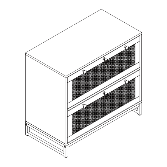
- Page 1 VINGLI FILE CABINET FC0WRLO/FC0W2LB/FC0W2LW...
- Page 5 MODEL&ASSEMBLY TIPS OVERALL SIZE:...
-
Page 6: Identify Parts
IDENTIFY PARTS... -
Page 7: Part List
PART LIST Right Panel Bottom Panel Top Panel Left Panel Iron Side Frame Back Panel Back Connecting Strip Brace Iron Brace Drawr Back Panel Drawer Bottom Panel Drawer Front Panel Drawer Support Panel Upper Dawer Left Panel Lower Drawer Left Panel Drawer Right Panel... - Page 8 PART LIST Ax16(+1) Bx16(+1) Cx10(+1) Dx16(+1) 6x35mm 15x10mm 4x35mm 6x30mm Wood Dowel Cam Bolt Cam Lock Wood Dowel Hx30(+3) 3.5x12mm M6x30mm M6x40mm Anti-Tipping Device Screw Screw Screw Mending Wedge Adjustable Leveler Hexagon Wrench Drawer Slide 3x16mm Anti-tipping Belt Screw Round Handle Screw Screw Rx11(+1) 3.5x16mm...
- Page 9 ASSEBMLY STEPS...
- Page 10 ASSEBMLY STEPS STEP 1 Kind Tips: The pre-drilled holes for locating the drawer slides are relatively small, look carefully. Please don't worry, they are there Front View Back View 3.5x12mm Hx12...
- Page 11 ASSEBMLY STEPS STEP 2 Fix the Anti-Tipping Device(E) on Panel #3 with Screws(R) R R R 3.5x16mm...
- Page 12 ASSEBMLY STEPS STEP 3 Screw the cam bolt (A) onto the panels # 1, # 3 and # 4 6x35mm...
- Page 13 ASSEBMLY STEPS STEP 4 Insert Wood Dowel(C) into Panel #5 first,and then connect Panel#4 to it with Cam Lock(B) 15x10mm 6x30mm...
- Page 14 ASSEBMLY STEPS STEP 5 Insert Wood Dowel(C) into Panel #5 first,and then connect Panel #3 to them with Cam Lock(B) 15x10mm 6x30mm...
- Page 15 ASSEBMLY STEPS STEP6 Insert Wood Dowel(C) into Panel #3 #4 first, and then connect Panel #2 to them with Screw(D) 4x35mm 6x30mm...
- Page 16 ASSEBMLY STEPS STEP 7 Build the iron frame part M6x40mm...
- Page 17 ASSEBMLY STEPS STEP 8 Connect the iron frame part to Panel #2 with Screw(G) M6x30mm...
- Page 18 ASSEBMLY STEPS STEP 9 Connect the Adjustable Levelers to the bottom...
- Page 19 ASSEBMLY STEPS STEP 10 First, clip two Panel #6 and Back Connecting Strip #7 together, and then push them in along the grooves on Panel #3 #4...
- Page 20 ASSEBMLY STEPS STEP 11 Insert Wood Dowel(C) into the top of Panel #3 #4 first and then connect Panel #1 to the cabinet body with Cam Lock(B) 15x10mm 6x30mm...
- Page 21 ASSEBMLY STEPS STEP 12 Fix the Mending Wedge(L) with Screw(O) as picture shows for more stability Use screws (N) to fix the Anti-tipping Belt(M) to Panel #3 #4, and add Washer(X) in the middle 3x16mm...
- Page 22 ASSEBMLY STEPS STEP 13 Screw Cam Bolt(A) to Panel #10; Fix Lock and Handles to Panel #10 as picture shows 3.5x16mm 6x35mm Ax10...
- Page 23 ASSEBMLY STEPS STEP 14 Connect the Drawer Back Panel #11 to the Drawer Support Panel #15 with Screw (D). Note to distinguish the front and back of the Drawer Support Panel 4x35mm...
- Page 24 ASSEBMLY STEPS STEP 15 Attach the Drawer Slide(J-2) to Panel #13 #14 with Screw(H) Fix Anti-Tipping Device(S) to Panel #13 with Screw(H) Front Back 3.5x12mm J-2x2...
- Page 25 ASSEBMLY STEPS STEP 16 Insert the long rod (U) into the drawer side panel, then screw (D) the drawer side panel # 14 # 16 over the drawer back panel # 11. 4x35mm...
- Page 26 ASSEBMLY STEPS STEP 17 Insert Panel #12 along with the groove; Insert the Short Hanging Rod(V) into Panel #11 before next step...
- Page 27 ASSEBMLY STEPS STEP 18 Attach Panel #10 to the drawer body with Cam Lock(B) 15x10mm...
- Page 28 ASSEBMLY STEPS STEP 19 Attach the Drawer Slide(J-2) to Panel #16 #14 with Screw(H) Fix Anti-Tipping Device(S) to Panel #16 with Screw(H) Front Back 3.5x12mm J-2x2...
- Page 29 ASSEBMLY STEPS STEP 20 Insert the long rod (U) into the drawer side panel, then screw (D) the drawer side panel # 14 # 16 over the drawer back panel # 11. 4x35mm...
- Page 30 ASSEBMLY STEPS STEP 21 Insert Panel #12 along with the groove; Insert the Short Hanging Rod(V) into Panel #11 before next step...
- Page 31 ASSEBMLY STEPS STEP 22 Attach Panel #10 to the drawer body with Cam Lock(B) 15x10mm...
- Page 32 ASSEBMLY STEPS STEP 23 Drill holes in the wall, insert Expansion Screw(W), and fix the item to the wall with Screw(D) for safe use WALL WALL WALL drilling hole 6x30mm WALL 4x35mm 6x30mm...
- Page 33 ASSEBMLY STEPS STEP 24 Pull Drawer Slide(J-1) out first, and the ball along with it to the front; Keep the drawer level and insert the drawer with the slides aligned.Note! Failure to level may result in damage to the slides Push the upper snap to the front, and then install the upper drawer...
- Page 34 ASSEBMLY STEPS STEP 25 Pull Drawer Slide(J-1) out first, and the ball along with it to the front; Keep the drawer level and insert the drawer with the slides aligned.Note! Failure to level may result in damage to the slides Push the lower snap to the front, and then install the lower drawer...
- Page 35 ASSEBMLY STEPS STEP 26 The upper and lower drawers cannot be opened at the same time, one drawer must be closed...
- Page 36 ASSEBMLY STEPS STEP 27 The installation is complete WALL...
- Page 37 OPTIONS OF FILE STORAGE Option 1 Option 2 Letter Letter Option 3 Legal Option 4 Legal Place the Movable Hanging Rods as needed...
- Page 38 FAQS 1. What should I do when I received a defected item or missing parts? Please feel free to contact VINGLI customer service via the link where you purchased this item with your order ID, pictures & sticker number of the defective/missing parts to us.
Need help?
Do you have a question about the FC0WRLO and is the answer not in the manual?
Questions and answers